Hoveround mpv5 Owner's Manual And Warranty
Hide thumbs
Also See for mpv5:
- Owner's manual (68 pages) ,
- Instruction manual (4 pages) ,
- Owner's manual (3 pages)
Table of Contents
Advertisement
Advertisement
Table of Contents

Subscribe to Our Youtube Channel
Related Manuals for Hoveround mpv5


Summary of Contents for Hoveround mpv5
- Page 2 D82008753R 10/15...
-
Page 3: Special Notes
HOVEROUND CORPORATION. Neither HOVEROUND CORPORATION nor its affiliates shall be liable to the purchaser of this product or third parties for damages, losses, cost or expenses incurred by purchaser or third parties as a result of accident, misuse, or abuse of this product or unauthorized modification, repairs, or alterations to this product. - Page 4 MPV5 to fulfill your personal mobility needs. The MPV5 has the same innovation of design that is the hallmark of our company. It is compact yet very stable; attractive yet rugged; simple yet functional; gentle yet powerful; and above all, the MPV5 provides an outstanding level of maneuverability.
-
Page 5: Table Of Contents
Entering Your MPV5 ....... . 15 Driving Your MPV5 ....... . . 16 Joystick Controller . - Page 6 Routine Maintenance ....... . 41 Chapter 7 Disassembling and Reassembling Your MPV5 ®...
-
Page 7: Introduction
Service Service is our commitment to our clients and their continued mobility is our priority. In the event that you need assistance with your Hoveround, our Service Representatives are just a phone call away. Just call Hoveround Technical Support and Repair, toll free at 1-800-96-HOVER (1-800-964-6837). -
Page 8: General Warnings / Before You Use Your Mpv5
Never modify your wheelchair, and do not use accessories other than those developed for use specifically with your Hoveround MPV5 power wheelchair. Information about the design of ramps appropriate... - Page 9 Stop using your power wheelchair immediately, and call for assistance if: • Your power wheelchair is not working correctly. • Your seat belt does not latch or stay latched. • You are taking medications, drugs, or alcohol that affect your ability to safely drive. •...
- Page 10 To reduce the chance of serious injury or death from tip-over, collision with obstacles and other people, loss of control, or falling from the power wheelchair, drive in proper environments: • Do not drive across or sideways on a ramp or slope; go straight up or down.
- Page 11 To avoid serious injury or death from being struck by a motor vehicle, when driving your power wheelchair near traffic: • Obey all local pedestrian traffic rules. • Cross roads at locations where you are most visible to motor traffic, if possible at a light-controlled pedestrian crossing with handicapped cutouts.
-
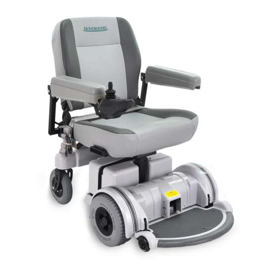
Page 12: Hoveround Mpv5 / Diagram
Seat Belt Seat • (Swivel Optional) • Batteries • • Brake Release • Battery Cable Levers Connection • (if equipped) Dual Motor Front • Wheel Drive • Flip Up Footplate • Anti Tip Wheels Hoveround MPV5 - Diagram D82008753R 10/15... -
Page 13: Hoveround Mpv5 / Warning Labels
20V/m. • • • • Turn the power off before exiting the seat or changing the joystick position. Drive • • Brake Levers Release Maximum Capacity 300LB Read Owner’s Manual before operating vehicle. D82008753R 10/15 Hoveround MPV5 - Warning labels... - Page 14 EMI, Warning Label General Warnings D82008753R 10/15...
-
Page 15: Chapter 1 Operating Instructions
• Always fasten seat belt to maintain proper positioning in the seat. Set speed/response control of joystick to minimum while learning to drive the power wheelchair. ® Entering Your MPV5 1. Be sure the power is turned “OFF” before entering or exiting your Hoveround ®... -
Page 16: Driving Your Mpv5
6. Move the footplate down and position your feet on the foot plate. ® Driving Your MPV5 Power Wheelchair • Sudden change in motion, loss of control, or tip-over may cause a collision or fall from the seat and result in serious injury or death. - Page 17 To avoid serious injury or death from a fall or collision, set speed/response control for the environment and your skill level. Set control to minimum if you are a less experienced driver or are in a confined space. 5. Gently move the joystick forward. A “click” will be heard as the controller releases the motor brakes and your power wheelchair will move slowly forward.
-
Page 18: Joystick Controller
Joystick Controller All the controls and indicators necessary to drive your MPV5 are located on the joystick controller. See Figures 1A - 1B to identify your controller. 1. ON/OFF - Press to turn the system on and off. - Page 19 Figure 1A- VSI Controller D82008753R 10/15 Chapter 1...
- Page 20 Figure 1B - new VSI Controller Chapter 1 D82008753R 10/15...
-
Page 21: Chapter 2 Batteries And Charging
Chapter 2 Batteries and Charging Caring For Your Batteries • Completely read and follow all warnings about the batteries in this user instruction manual and any labels applied to the product. Failure to do so could result in fire, explosion, injury and/or death. -
Page 22: Battery Replacement
• Do not let your batteries run down. Battery Replacement When it becomes necessary to replace batteries, consult with Hoveround Technical Support 1-800-96-HOVER (1-800-964-6837). We will provide you with the replacement battery to ensure the proper operation of your power wheelchair. -
Page 23: Charging Your Batteries
It may take up to 8 hours for a full recharge. We recommend an overnight charge after the day’s use of your power wheelchair. • ALWAYS use the charger and connectors supplied with your Hoveround ® power wheelchair. • DO NOT use the charger outdoors or in areas unsheltered from the weather. - Page 24 • ONLY USE to charge AGM sealed lead acid batteries. Do not attempt to charge any other type of battery or any non-rechargeable type of battery. • DO NOT attempt to use the charger as a DC power source for any electrical or other equipment. •...
- Page 25 4. Plug the AC power cord into the back of the charger. 5. Plug the other end of the AC power cord into a 120-volt grounded household power outlet. 6. Follow the specific instructions for your charger. Charger instructions begin on page 24. 7.
-
Page 26: Chapter 3 Manual Brake Release Levers
Chapter 3 Manual Brake Release Levers On occasion it may be necessary to push your Hoveround ® power wheelchair. Each motor has a manual brake release lever. Refer to Figure 3A below to locate the manual brake release levers on your power wheelchair. -
Page 27: Seating And Pressure Relief
Chapter 4 Seating and Pressure Relief • Unintentional or unexpected motion increases the chances of a collision or fall from the seat and can result in serious injury or death. Press the power button to OFF before making any adjustments to your power wheelchair. •... -
Page 28: Seat Belt Adjustment
Seat Belt Adjustment • Always fasten seat belt to maintain proper positioning in the seat and avoid injury. • Replace seat belt immediately at first signs of wear or improper latching. To fasten the seat belt, push the metal tab into the buckle until it clicks. -
Page 29: Arm Angle Adjustment
Arm Angle Adjustments The seat arms have angle adjustments to suit your driving and comfort requirements. To adjust the arm angle on the seat arms, lift the arm and locate the adjustment bolt near the pivot point. Refer to Figure 4D below. Use the supplied 1/4 inch hex wrench to make the adjustment. -
Page 30: Swivel Seat
This feature is provided to make side transferring easier. The swivel release lever is mounted on the left side in the standard position, and can be changed to the right side by a Hoveround ® Field Service Technician. -
Page 31: Arm Width Adjustment
Arm Width Adjustment The standard seat has arm width adjustment (Figure 4F and 4G). To adjust the arm width: 1. Locate the two knobs and two set screws on the square tube at the rear of the seat. 2. Loosen the knobs and set screws. 3. -
Page 32: Raising And Lowering Seat Height
Raising and Lowering Seat Height To raise the seat from the factory delivered setting, a collar and lock pin are required (Figure 4J). If you need the collar and lock pin, contact Hoveround ® Technical Support at 1-800-96-HOVER (1-800-964-6837). 1. Loosen the locking bolt on the corner of the seat post, using the 1/4 inch hex wrench supplied with the chair. -
Page 33: Footplate Angle Adjustment
3. Lower footplate. The bolt heads should come in contact with the stop (caster wheel bracket Figure 4 N) Figure 4N Figure 4M If the footplate does not remain upright, the footplate tension requires adjustment. Contact Hoveround ® Technical support at 1-800-96-HOVER (1-800-964-6837), immediately. D82008753R 10/15... -
Page 34: Seat Back Angle Adjustment
Seat Back Angle Adjustment The seat back has fixed positions to select from (Figure 4P). To change the back angle position: 1. Locate the screw and nut on the left hinge and right hinge. 2. Remove the screw and nut and place the back in the desired angle position. -
Page 35: Locking The Seat Back
(Figure 4Q). If you prefer to have the seat back locked into place and stationary; screws and a hex key have been provided with your Hoveround to lock the seat back. Figure 4Q 1. Locate the holes on each side of the seat back frame above the angle adjustment hinge. -
Page 36: Reclining Back Seat
Reclining Back Seat (May require medical necessity) Driving with the seatback reclined makes it difficult to see where you are going and increases the chance of serious injury or death from collision and tip-over. Do not attempt to drive this vehicle with seatback reclined. -
Page 37: Options And Accessories
Optional tie-down kit is available. Please contact Hoveround for additional information. Optional tie-down kit is intended for the wheelchair security, it is not intended to secure the rider. - Page 38 Press either seat symbol button to activate the PSL mode (see Figure 5A below). When the indicator light is lit, move the joystick forward to raise the seat, back to lower. The MPV5 ® will not drive while seat is raised and light is on.
- Page 39 Optional Legrests or Footrests Install each leg/footrest on to the appropriate hanger bracket and swing into the forward facing position. If elevating legrests are installed, set the angle to the lowest possible position. Fold down the foot plates. Your feet should comfortably rest on the plates without a tendency to lift your thighs from the seat cushion.
- Page 40 Chapter 5 D82008753R 10/15...
-
Page 41: Routine Maintenance
Routine Maintenance Service and maintenance are very important to ensure the performance and the safe operation of your power wheelchair. Service Please contact Hoveround ® Technical Support at 1-800-96-HOVER (1-800-964-6837) for any service or maintenance needs. Stop using your power wheelchair immediately, and call for assistance if: •... - Page 42 Owner Maintenance Daily • Check drive tires. • Charge batteries (or as required). • Check that the seat belt latches and does not show signs of wear. Weekly • Check tire treads and pressure. (Should be 45-50 psi.). • Check that casters are free to pivot. •...
- Page 43 ® Cleaning your MPV5 The MPV5 is designed to operate both inside and outside the home. To keep the vehicle clean: Seat – Wipe with a damp cloth or towel, using a mild detergent or window cleaner. Tires – Brush-off loose material with a dry bristle brush and wipe with a damp cloth or towel.
-
Page 44: Disassembling And Reassembling Your Mpv5
Chapter 7 ® Disassembling and Reassembling Your MPV5 Controller Removal/Replacement Removal 1. Check that vehicle power is OFF. 2. Lift the arm and loosen the socket head cap screw closest to the controller. Use the 1/4 inch hex wrench supplied with your chair (See Figure 7A, below). -
Page 45: Removing And Replacing The Seat
Seat Removal/Replacement Removal 1. Remove controller. 2. Remove the controller cable from the seat base by releasing the Velcro strap at the rear of the seat or opening the seat clip at the side of the seat, depending on the type of seat you have. Open the clip by pinching the small tabs on the clip with one hand while removing the strap with your other hand. -
Page 46: Removing And Replacing Batteries
The cable that joins the joystick to the junction box is a critical part of the vehicle. Ample cable is provided to allow for adjustments. There is a danger if this cable is not correctly routed. Do not allow the excess cable to extend beyond the width of the chair where it may become damaged. - Page 47 ® Battery Removal/Replacement MPV5 S/N 5800000+ Turn the joystick off before attempting to remove the batteries. To prevent short circuit, fire or other hazards, prevent contact between the battery terminals and any surface that may cause a short, spark or other hazard.
-
Page 48: Electromagnetic Interference (Emi)
20 V/m immunity level, which would provide useful protection from the more common sources of radiated EMI. This MPV5 power wheelchair model, as shipped, without any further modification has a tested immunity level of at least 20 V/m. There are a number of sources of relatively intense electromagnetic fields in the everyday environment. - Page 49 The sources of radiated EMI can be broadly classified into three types. 1. Hand-held portable transceivers (transmitters-receivers) with the antennas mounted directly to the transmitting unit. Examples include: Citizen band (CB) radios, “walkie-talkie”, security, fire, and police transceivers, cellular telephones and other personal communication devices.
-
Page 50: Important Information
1. 20 volts per meter (V/m) is a generally achievable and useful immunity level against interference from radio wave sources (as of May 1994, the higher the level, the greater the protection). 2. The MPV5 ® wheelchair has an immunity level of at least 20 V/m. -
Page 51: Appendices
Chapter 9 Appendices Appendix A: Programmable Parameters The controller used on your power wheelchair is programmable for basic functions. It requires a programmer to make changes. Any changes must be made by a qualified technician only. The following chart indicates the standard program values of the factory settings. -
Page 52: Appendix B Fault Codes
The controller may prevent the chair from driving should a critical fault condition exist. Refer to the appropriate fault code section for the system used on your MPV5 ® When there is a fault please follow this procedure: A. - Page 53 If a fault occurs, you can find out what has happened by counting the number of bars on the battery gauge that are flashing. VSI Controller 1 bar: Low battery or a bad connection. Try recharging the battery. 2 bars: Bad connection to left motor. 3 bars: Short circuit, left motor to battery.
-
Page 54: Appendix C Locking Feature
Locking Feature Your MPV5 ® is equipped with a locking feature. Please refer to the appropriate instructions for the controller on your MPV5. Lock Sequence System ON / OFF Button Joystick Figure 9A - VSI Controller and new VSI Controller 1. -
Page 55: Appendix D Specifications
Appendix D: ® MPV5 Specifications Performance Maximum Speed* 4 mph Range (per battery charge)* 12 miles Capacity 300 lbs Turning Radius 22.7" Ground Clearance 2.5" Maximum step climb 2" Maximum grade climb 6° (5° ADA ramp recommended) Dimensions and weight (with 20" seat in lowest position) Length 38"... -
Page 56: Appendix E Record Of Service
Appendix E: Record of Service Date Technician Service Performed Chapter 9 D82008753R 10/15... - Page 57 Record of Service Date Technician Service Performed D82008753R 10/15 Chapter 9...
-
Page 58: Limited Warranty
(excluding all upholstery, tires, tubes, foot mats, body plastic and batteries) to be free from defects in materials and workmanship for a period of one (1) year from the date of purchase. Hoveround Corporation warrants batteries to be free from defects in materials or workmanship for a period of six (6) months from the date of purchase. - Page 59 D82008753R 10/15...
Need help?
Do you have a question about the mpv5 and is the answer not in the manual?
Questions and answers