Table of Contents
Advertisement
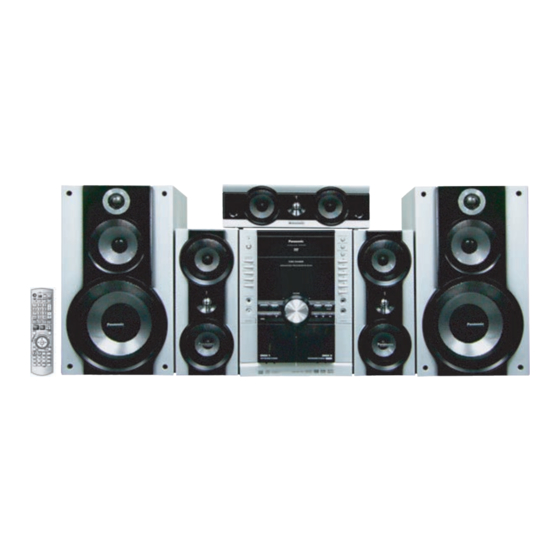
Stereo System SC-TM910DVD
MODEL
SC-TM910DVD SA-TM910DVD Stereo
SB-TM910
SB-PC950
SB-PS950
UNIDAD PRINCIPAL
POTENCIA DE SALIDA:
CONSUMO DE POTENCIA:
ALIMENTACION:
SENSIBILIDAD MUSIC PORT:
SENSIBILIDAD AUX:
RANGO DE SINTONIA AM:
87.9 - 107.9 MHz (paso de 0,2 MHz)
RANGO DE SINTONIA FM:
87.5 - 108.0 MHz (paso de 0,1 MHz)
DIMENSIONES (b x h x l)
PESO:
IMPEDANCIA DE ENTRADA
Bocina Super Woofer
Bocina Woofer
Bocina Tweeter
Super Tweeter
Dimensiones (b x h x l)
Peso
(El peso y las dimensiones son de un solo bafle)
UNIT
Front Speaker
Center Speaker
Surround
SA-TM910DVD
7000 W (P.M.P.O.)
310 W
127 V ca ±10% 60 Hz
100 mV
250 mV
520 - 1710 kHz (paso de 10 kHz)
250 mm x 330 mm x 348 mm
5.4 kg aprox.
ESPECIFICACIONES POR CADA BAFLE
SB-TM960
Alto 3 Ω, Bajo 3 Ω
250 mm x 429 mm x 318.5 mm 140 mm x 330 mm x 155.8 mm
6.2 kg aprox.
SB-TM910
SB-PS950
Specifications
POTENCIA DE SALIDA (AMPLIFICADOR)
Frontal (Alto) 110 W RCM por canal (3Ω) 1kHz, 10% DAT
(Bajo) 110 W RCM por canal (3Ω) 100Hz, 10% DAT
SC-TM910DVD
Surround
Central
FRONTAL
SURROUND
SB-PS950
3 Ω
20 cm
- - - - -
12 cm
8 cm
6 cm
6 cm
1.3 kg aprox.
Colour (S)... Silver Type
SB-PC950
SB-PS950
SA-TM910DVD
110 W RCM por canal (3Ω) 1kHz, 10% DAT
110 W RCM por canal (3Ω)1kHz, 10% DAT
CENTRAL
SB-PC950
3 Ω
- - - - -
8 cm x 2
- - - - -
Piezo type
409 mm x 104 mm x 155.5 mm
1.5 kg aprox.
SB-TM910
Advertisement
Table of Contents

Related Manuals for Panasonic SC-TM910DVD


Summary of Contents for Panasonic SC-TM910DVD
-
Page 1: Center Speaker
Stereo System SC-TM910DVD Colour (S)... Silver Type SB-PC950 MODEL UNIT SC-TM910DVD SA-TM910DVD Stereo SB-TM910 Front Speaker SB-PC950 Center Speaker SB-PS950 Surround SB-TM910 SB-PS950 SB-PS950 SB-TM910 SA-TM910DVD SA-TM910DVD UNIDAD PRINCIPAL POTENCIA DE SALIDA: 7000 W (P.M.P.O.) CONSUMO DE POTENCIA: 310 W ALIMENTACION: 127 V ca ±10% 60 Hz... - Page 2 (Sub sampling is 4:0:0, 4:2:0, 4:2:2 or 4:4:4). Extremely long and narrow pictures may not be displayed. MPEG-1 Layer 3, MPEG-2 Layer 3 MPEG4 data recorded with the Panasonic SD multi cameras or DVD video recorders. Conforming to SD VIDEO specifications (ASF standard) / MPEG4 (Simple Profile) video system / G.726 audio system...
- Page 3 Notes: 1. Specifications are subject to change without notice. Mass and dimensions are approximate. 2. Total harmonic distortion is measured by the digital spectrum analyzer. manual de servicio SC-TM910DVD...
-
Page 4: Safety Precautions
1/2 milliamp. In case a measurement is out of the limits specified, there is a possibility of a shock hazard, and the equipment should be repaired and rechecked before it is returned to the customer. manual de servicio SC-TM910DVD... -
Page 5: Safety Precaution For Ac Power Supply Cord (For Gs Only)
“shorted”, or if speaker systems with an impedance less than the indicated rated impedance of the amplifier are used. If this occurs, follow the procedure outlines below: 1. Turn off the power. manual de servicio SC-TM910DVD 2. Determine the cause of the problem and correct it. - Page 6 3. Turn on the power once again after one minute. Note : When the protection circuitry functions, the unit will not operate unless the power is first turned off and then on again. manual de servicio SC-TM910DVD...
-
Page 7: Prevention Of Electrostatic Discharge (Esd) To Electrostatically Sensitive (Es) Devices
8. Minimize body motions when handling unpackaged replacement ES devices. (Otherwise harmless motion such as the brushing together of your clothes fabric or the lifting of your foot from a carpeted floor can generate static electricity (ESD) sufficient to damage an ES device). manual de servicio SC-TM910DVD... -
Page 8: Handling Precautions For Traverse Unit
Place a conductive material (conductive sheet) or ironboard where optical pickup is placed. (Refer to Fig. 3.2) Note : Keep your clothes away from optical pickup as wrist strap does not release the static electricity charged in clothes. manual de servicio SC-TM910DVD Fig. 3.2... -
Page 9: Precaution Of Laser Diode
4. Recommend not to look at pick up lens for a long time. CAUTION! THIS PRODUCT UTILIZES A LASER. USE OF CONTROLS OR ADJUSTMENTS OR PERFORMANCE OF PROCEDURES OTHER THAN THOSE SPECIFIED HEREIN MAY RESULT IN HAZARDOUS RADIATION EXPOSURE. n Use of Caution Labels manual de servicio SC-TM910DVD... -
Page 10: Service Caution Based On Legal Restrictions
• The following 3 types of lead free solder are available through the service parts route. RFKZ03D01K-----------(0.3mm 100g Reel) RFKZ06D01K-----------(0.6mm 100g Reel) RFKZ10D01K-----------(1.0mm 100g Reel) Note * Ingredient: Tin (Sn), 96.5%, Silver (Ag) 3.0%, Copper (Cu) 0.5%, Cobalt (Co) / Germanium (Ge) 0.1 to 0.3% manual de servicio SC-TM910DVD... - Page 11 Pilas para el mando a distancia ...... UM-3PA/T Antena interior de FM ......RSA0007-L Antena de cuadro de AM ......ND1AAAA00002 Mando a distancia ..EUR7662YM0 Plug para RCA/ Jack 3.5 ..KM19201-01 Cable de video ...... K2KA2CA00011 manual de servicio SC-TM910DVD...
- Page 12 Botón de selección avance rápido/rebobinado de DECK 1 (➡ 23) de audiocinta, sintonización, botones de ajuste de hora) , RECORD (➡ 24, 30) (➡ 8, 9, 23, 32) – VOLUME + (➡ 12, 25) manual de servicio SC-TM910DVD...
- Page 13 , PAUSE (➡ 12) REPEAT (➡ 13, 23) SOUND (➡ 27) FL DISPLAY (➡ 12) S. WOOFER (➡ 28) C.FOCUS (➡ 27) V. MUTE, ECHO (➡ 26) MUTING (➡ 30) AUDIO (➡ 25) CH SELECT, -TEST(➡ 28) manual de servicio SC-TM910DVD...
-
Page 14: Disc Information
7.3. Disc Information 7.3.1. Disc Playability manual de servicio SC-TM910DVD... - Page 15 7.3.2. To Play MP3/ WMA and still Pictures (JPEG/ tiff) manual de servicio SC-TM910DVD...
-
Page 16: Divx Vod Content
7.4. DivX VOD Content manual de servicio SC-TM910DVD... -
Page 17: New Features
8 New Features 8.1. CRS1D Mechanism Overview manual de servicio SC-TM910DVD... -
Page 18: General Feature
Play & Open Tray-* The state where one of the tray is in playing position performing recording or reproducing, other trays can manual de servicio SC-TM910DVD be used (OPEN position) for disc exchanging without stopping the recording or reproducing process. -
Page 19: Music Port
• Exploded View and Parts List for individual parts of the CD/DVD Mechanism drive. Please refer to the original service manual (Order No. MD0603065A3) for the CD/DVD Mechanism Drive CRS1D. 8.2. Music Port With reference to page 31 of the operating instruction manual. manual de servicio SC-TM910DVD... -
Page 20: About Highmat
A Problem Defined:Today, when consumers create their own digital audio, video or photo collections on CD-R or other physical formats, there are numerous, inconsistent ways that devices read the data. For the consumer, the playback experience can be confusing: manual de servicio SC-TM910DVD... -
Page 21: Benefits Of Highmat
HighMAT compatible products play content back with consistent that various DVD players can read the music or photos files often leads interface. This includes products which are JPEG compatible products to a confusing and inconsistant playback experince. without HighMAT support. manual de servicio SC-TM910DVD... - Page 22 SC-TM910DVD...
- Page 23 To enjoy the benefits of HighMAT, all you need is software that supports HighMAT for CD burning of music or photos, as well as a home entertainment device like a DVD player that supports HighMAT for playback. Always look for the HighMAT logo on your software or home entertainment device to ensure it supports the HighMAT experience. manual de servicio SC-TM910DVD...
-
Page 24: Self Diagnosis And Special Mode Setting
“1” or “2” button out and displayed. on the remote control unit. Press STOP or PLAY button to exit. The value is shown in hexadecimal notation. The above example shows the data in ADSC address OFAh is 6901h. manual de servicio SC-TM910DVD... - Page 25 Region display & mode In STOP (no disc) mode, press STOP “2” represents for GC/ GS button on the player, and “6” button on the “3” represents for GCS/ GCT remote control unit. Cancelled automatically 5 seconds later. manual de servicio SC-TM910DVD...
- Page 26 In STOP (no disc) mode, press STOP ation error display communication errors between button on the player, and “MENU” button system control IC and mechanism on the remote control unit. control IC. Cancelled automatically 5 seconds later. manual de servicio SC-TM910DVD...
- Page 27 Spindle motor operation timer. button on the player, and “ “ button on the remote control unit. Cancelled automatically 5 seconds later. Time is shown in 5 digits of decimal notation in a unit of 10 hours. manual de servicio SC-TM910DVD...
-
Page 28: Dvd Self-Diagnostic Function Error Code
Press [ ] on main There is no PGMAP. unit for next error. F061 DVD Media disk Although C_POSIT exists, it is in PGC. Press [ ] on main There is no PGMAP. unit for next error. manual de servicio SC-TM910DVD... - Page 29 Press [ ] on main violation during highlight display unit for next error. F4FF Force initialize failure Timeout when force initialization fails Press [ ] on main (time out) unit for next error. manual de servicio SC-TM910DVD...
- Page 30 ] on main does not end disc manager unit for next error. F702 Message command Message is changed before it is sent as Press [ ] on main changes a reply to disc manager unit for next error. manual de servicio SC-TM910DVD...
-
Page 31: Optical Pickup Breakdown Diagnosis
Replacement of optical pickup generally requires when the present value of laser drive exceeds 45 (DVD) or 45 (CD). Note: Start diagnosis within three minutes after turning on the power (as diagnosis fails when the unit becomes warm). manual de servicio SC-TM910DVD... -
Page 32: Special Mode Table
1. Select [ ] for CD mode. (CRS1D) Changer Unit. 2. Press [1] on remote control.. To exit, press button on main unit or remote control. (The tray will return to PLAY position and then manual de servicio SC-TM910DVD power off) - Page 33 Step 2: Check for firmware version and EEPROM checksum (By pressing STOP button on main unit followed by “4” and “7” on remote control). manual de servicio SC-TM910DVD • When entering into DOCTOR MODE, the firmware version and checksum data of EEPROM (if applicable) will appear on FL...
- Page 34 ROM correction checksum refers to the HEX code that is displayed upon key buttons pressed if an EEPROM is loaded in the unit. 10.3.2. CD/DVD changer unit ageing test mode Below is the process flow chart of ageing for the CD/DVD changer unit. (CRS1D) manual de servicio SC-TM910DVD...
- Page 35 SC-TM910DVD...
-
Page 36: Error Code Table
For DVD unit (For Traverse). between CD Servo the sense signal does Press [ ] on main unit for LSI IC and not turn “Low”, a fail safe next error. microprocessor IC time after system command transmission manual de servicio SC-TM910DVD is sent. - Page 37 For CD/DVD changer unit (CRS1D). assembly abnormal move “HOME” Press [SINGLE CHANGE] on main unit position under following for next error. conditions 1. After tray is load to “PLAY” position. 2. After tray is unload to “STOCK” position. manual de servicio SC-TM910DVD...
- Page 38 1. The errors that occured in CRS1D Mechanism can be recalled and displayed, in the order of the occurence under self- diagnostic (Refer to Section 10.3 for procedures to enter this mode. manual de servicio SC-TM910DVD • Only the first 5 errors will be memorized (in backup memory). The subsequence error shall be ignored and not memorize.
- Page 39 [4 _ _ _ _ L O A D] → [SINGLE CHANGE] [5 _ _ _ _ _ U D D] → [SINGLE CHANGE] 3. To clear the error code memory In CRS1D Self-Diagnostic mode, long press [SINGLE CHANGE] key (2s or more) manual de servicio SC-TM910DVD...
-
Page 40: Assembling And Disassembling
• Disassembly of Deck Mechanism Unit • Disassembly for Deck P.C.B. • Disassembly of Traverse Unit • Disassembly of Optical Pickup Unit (CD/DVD Mechanism) • Disassembly of Deck Mechanism • Replacement for cassette lid • Rectification for tape jam problem manual de servicio SC-TM910DVD... -
Page 41: Disassembly Flow Chart
11.2. Disassembly flow chart The following chart is the procedure for disassembling the casing and inside parts for internal inspection when carrying out the servicing. To assemble the unit, reverse the steps shown in the chart as below. manual de servicio SC-TM910DVD... -
Page 42: Main Parts Location
11.3. Main Parts Location manual de servicio SC-TM910DVD... -
Page 43: Disassembly Of Top Cabinet
Step 1 Remove 2 screws at rear panel. Step 2 Detach the FFC cables (CN2038 & CN2036). Step 3 Release the claws on both ends. Step 4 Lift the CD/DVD changer unit upwards to remove it. manual de servicio SC-TM910DVD... -
Page 44: Disassembly Of Rear Panel
* The differentiate the screws for the GC with GS/GCS/GCT, just because of the Voltage Selector. Step 2 Remove 2 screws at Speaker P.C.B.. Step 3 Detach the fan wires CNP2913 & CNP2914 from Main P.C.B.. Step 4 Remove rear panel. manual de servicio SC-TM910DVD... -
Page 45: Disassembly Of Main P.c.b
• Follow the (Step 1) - (Step 4) of Item 11.5 - Disassembly of CD/DVD Changer Unit Step 1 Disconnect connectors (CN2602, CNP2601, CNP2101 and CN5904). Step 3 Release 2 claws. Step 2 Bent the front panel unit slightly forward as shown. manual de servicio SC-TM910DVD... -
Page 46: Disassembly Of Smps P.c.b
• Follow the (Step 1) - (Step 3) of Item 11.7 - Disassembly of Main P.C.B. • Follow the (Step 1) - (Step 4) of Item 11.8 - Disassembly of Front Panel Unit Step 1 Remove 1 screw. manual de servicio SC-TM910DVD... - Page 47 11.12. Replacement for Power Amp IC (Digital Amp P.C.B.) • Follow the (Step 1) - (Step 3) of Item 11.11 - Disassembly of Digital Amp P.C.B. Replament of Power Amp IC (IC5100) Step 1 Remove IC clip. • IC5100 manual de servicio SC-TM910DVD...
- Page 48 Step 3 Lift up the Mic P.C.B to remove it. Step 4 Remove 6 screws. Step 5 Release 2 catches. Step 6 Remove Panel P.C.B.. 11.13.1. Disassembly of Tact Switch P.C.B. manual de servicio SC-TM910DVD Step 7 Remove the Volume knob & Mic Volume Knob.
-
Page 49: Disassembly Of Lid
• Follow the (Step 1) - (Step 4) of Item 11.5 - Disassembly of CD/DVD Changer Unit • Follow the (Step 1) - (Step 4) of Item 11.8 - Disassembly of Front Panel Unit Step 1 Remove 2 screws. manual de servicio SC-TM910DVD... -
Page 50: Disassembly Of Traverse Unit
For procedures to set the trays in “STOCK” position, please refer to original Service Manual for CRS1D, Section 4.3. Setting the trays in “STOCK” position, Order No. MD0603065A3. • Assembly of Traverse Unit manual de servicio SC-TM910DVD... - Page 51 • Follow the (Step 1) - (Step 4) of Item 11.5 - Disassembly of CD/DVD Changer Unit • Follow the (Step 1) - (Step 2) of Item 11.16 - Disassembly of Traverse Unit Step 1 Pull out FFC. Step 3 Remove 4 pins. Step 2 Widening the catch, push the pin in. manual de servicio SC-TM910DVD...
- Page 52 Note: Insert a short pin into FFC of the optical pickup. pickup. Step 7 Rotate the traverse deck (B) to the arrow direction and shift the optical pickup to the furthest backward. manual de servicio SC-TM910DVD...
-
Page 53: Disassembly Of Deck Mechanism
• Follow the (Step 1) - (Step 5) of Item 11.14 - Disassembly of Deck Mechanism Unit 11.18.1. Disassembly of the pinch roller ass’y and head block * The mechanism as shown below is for DECK1. For DECK 2, perform the same procedures. manual de servicio SC-TM910DVD... - Page 54 Step 7 Release the claw and remove the winding lever and spring. [Installation of the belt] manual de servicio SC-TM910DVD Step 1 The boss and marking should be positioned Step 4 Remove 3 screws (for deck 1 & 2). horizontally.
- Page 55 Step 6 Install the flywheel R. Step 8 Put the capstan belt B on the motor ass’y pulley. Step 9 Install the sub chassis to the mechanism, and then tighten screws. manual de servicio SC-TM910DVD...
- Page 56 Step 10 Install 3 screws. Step 11 Put the capstan belt B as shown below. Step 12 Put the capstan belt A on the motor ass’y pulley. manual de servicio SC-TM910DVD...
-
Page 57: Replacement For Cassette Lid
F in the direction of the arrow to remove it. Step 2 Push the lever upward and open the cassette lid. manual de servicio SC-TM910DVD Remove the cassette tape. - Page 58 SC-TM910DVD...
-
Page 59: Service Fixture And Tools
(A) Deck P.C.B. - Main P.C.B. REEX0485 (14 Pins) (B) Panel P.C.B. - Deck Mechanism P.C.B. REEX0484 (10 Pins) 13 Service Positions Note: For description of the disassembly procedures, see the Section 11. 13.1. Checking and Repairing of Main P.C.B. manual de servicio SC-TM910DVD...
Need help?
Do you have a question about the SC-TM910DVD and is the answer not in the manual?
Questions and answers