Table of Contents
Advertisement
Service Manual
MODELO
SA-TM72DV
SB-VK81
SC-TM72DV
SB-PS81
SB-PC81
SB-WVK81
AMPLIFICADOR
POTENCIA DE SALIDA:
CONSUMO DE POTENCIA:
ALIMENTACION:
SENSIBILIDAD AUX:
RANGO DE SINTONIA AM:
RANGO DE SINTONIA FM:
DIMENSIONES (BXHXL):
PESO:
UNIDAD
Estéreo
Bafles
Surround
Central
Subwoofer
SC-TM72DV
4800 W (P.M.P.O.)
215 W
127 V ca
10% 60 Hz
250 mV
520 - 1710 kHz (paso de 10 kHz)
87,5 - 108,0 MHz (paso de 0,1 MHz)
87,9 - 107,9 MHz (paso de 0,2 MHz)
250 mm x 330 mm x 372 mm
9.6 kg aprox.
Modelo:
POTENCIA DE SALIDA (AMPLIFICADOR)
FRONTAL
SURROUND
SC-TM72DV
CENTRAL
SUBWOOFER
SC-TM72DV
90 W
RCM por canal
(6 ),
45 W
RCM por canal
(6 ),
90 W
RCM por canal
(6 ),
90 W
RCM por canal
(6 ),
Notas:
• Las especificaciones están sujetas a cambios sin previo aviso.
• Los pesos y las dimensiones son aproximados.
1
1 kHz, 10%
DAT
1 kHz, 10%
DAT
1 kHz, 10%
DAT
100 Hz, 10%
DAT
Advertisement
Table of Contents

Related Manuals for Panasonic SC-TM72DV


Summary of Contents for Panasonic SC-TM72DV
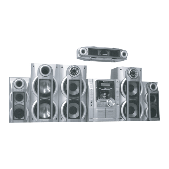
- Page 1 Service Manual UNIDAD MODELO SA-TM72DV Estéreo SB-VK81 Bafles SC-TM72DV SB-PS81 Surround SC-TM72DV SB-PC81 Central Modelo: SB-WVK81 Subwoofer AMPLIFICADOR SC-TM72DV POTENCIA DE SALIDA: 4800 W (P.M.P.O.) CONSUMO DE POTENCIA: 215 W ALIMENTACION: 127 V ca 10% 60 Hz 250 mV SENSIBILIDAD AUX:...
-
Page 2: Table Of Contents
Table Of Contents COVER 1 Before Use 2 Before Repair and Adjustment 3 Protection Circuitry 4 Safety Precautions 4.1 General Guidelines 4.1.1 Leakage Current Cold Check 4.1.2 Leakage Current Hot Check (See Figure 1) 5 Prevention of Electro Static Discharge (ESD) to Electrostatically Sensitive (ES) Devices 6 Handling the Lead-free Solder 6.1 About lead free solder (PbF) 7 Cautions to be taken when handling Optical Pickup... - Page 3 16.1 Recovery after the dvd player is repaired 16.2 DVD Player Firmware Version Upgrade Process 16.3 Firmware Version Upgrade Process by Using Disc and Recovery Process 16.3.1 Self-Diagnosis Function 16.4 Using Recovery Disc 16.4.1 Recovery Process 16.4.2 Version Upgrade Process 16.5 Total Usage Time Display 16.6 After replacement of DVD Module 17 Disassembly and Assembly of Main Component...
- Page 4 19.3.1 Cassette Deck Section 19.3.2 Adjustment Point 20 Block Diagram 21 Schematic Diagram 21.1 Optical Pickup Unit Circuit 21.2 (A) DVD Module Circuit 21.3 (B) Main Circuit 21.4 (C) Panel Circuit , (D) Mic Circuit & (E) Tact Switch Circuit 21.5 (F) Deck Circuit &...
-
Page 5: Before Use
1 Before Use Be sure to disconnect the mains cord before adjusting the voltage selector. Use a minus(-) screwdriver to set the voltage selector (on the rear panel) to the voltage setting for the area in which the unit will be used. -
Page 6: Protection Circuitry
Step2. Locate soldering Points as showed in Fig.2 Step3. Solder the first resistor between W2346 and (-)C2236 Fig3. Step4. Solder the second resistor between W2346 and (-)C2139 Fig3. Step 5. Add Diabond to fix the resistor to the PCB. Fig.3 3 Protection Circuitry The protection circuitry may have operated if either of the following conditions are noticed: No sound is heard when the power is turned on. -
Page 7: Safety Precautions
4 Safety Precautions 4.1 General Guidelines 4.1.1 Leakage Current Cold Check 4.1.2 Leakage Current Hot Check (See Figure 1) 4.1 General Guidelines 1. When servicing, observe the original lead dress. If a short circuit is found, replace all parts which have been overheated or damaged by the short circuit. -
Page 8: Leakage Current Hot Check (See Figure 1)
4.1.2 Leakage Current Hot Check (See Figure 1) 1. Plug the AC cord directly into the AC outlet. Do not use an isolation transformer for this check. 2. Connect a 1.5k? , 10 watts resistor, in parallel with a 0.15µF capacitor, betwee each exposed metallic part on the set and a good earth ground such as a water pipe, as shown in Figure 1. -
Page 9: Handling The Lead-Free Solder
6 Handling the Lead-free Solder 6.1 About lead free solder (PbF) 6.1 About lead free solder (PbF) Distinction of PbF P.C.B.: P.C.B.s (manufactured) using lead free solder will have a PbF stamp on the P.C.B. Caution: Pb free solder has a higher melting point than standard solder; Typically the melting point is 50 - 70°F (30 - 40°C) higher. •... -
Page 10: Replacing Precautions For Optical Pickup Unit
7.2 Replacing Precautions for Optical Pickup Unit DVD/CD Optical Pickup The optical pickup by which part supply was carried out attaches the short clip to the flexible board for laser diode electrostatic discharge damage prevention. Please remove the short clip and be sure to check that the short land is open, beforeconnecting. (Please remove solder, when the short land short-circuits.) 7.3 Grounding for Preventing Electrostatic Destruction... - Page 11 CAUTION! THIS PRODUCT UTILIZES A LASER. USE OF CONTROLS OR ADJUSTMENTS OR PERFORMANCE OF PROCEDURES OTHER THAN THOSE SPECIFIED HEREIN MAY RESULT IN HAZARDOUS RADIATION EXPOSURE. _ Use of Caution Labels (Inside of product)
-
Page 12: Accessories
9 Accessories Remote Control N2QAJB000110 FM Indoor Antenna RSA0007-L AM Indoor Antenna N1DAAA00001 Video Cable RJL1P016B15A... -
Page 13: Operation Procedures
10 Operation Procedures... -
Page 15: Disc Information
11 Disc information... -
Page 16: About Highmat
12 About HighMAT 12.1 What is HighMAT? 12.2 Why use HighMAT? 12.3 The advantages of using HighMAT 12.4 Outline of the HighMAT standard 12.1 What is HighMAT? This word combines the abbreviations of Matsushita Electric Industrial Co. Ltd. and High Performance Media Access Technology, and is a trademark of Microsoft Corporation. -
Page 17: The Advantages Of Using Highmat
12.3 The advantages of using HighMAT Applying the HighMAT standard will solve the following problems and will improve usability. • It will create a common user interface for both PC and consumer products. Regardless of the types of consumer products, such as DVD players, portable CD players, car stereos, and micro computers, a consistent way to pay for digital content will be created and it will make it easier to retrieve data. -
Page 18: Outline Of The Highmat Standard
12.4 Outline of the HighMAT standard Recording medium • CD-R/CD-RW • Supports ISO 9660 Level Expanded Joliet • For multiple session Support data format • Level 1 player: WMA, MP3 (MPEG-1 Audio Layer 3) • Level 2 player: WMA, MP3 (MPEG-1 Audio Layer 3), JPEG •... -
Page 19: Procedure For Repairing The Set
13 Procedure for repairing the set... -
Page 20: Distinguish The Problem
13.1 Distinguish the problem 13.1.1 Troubleshooting Guide Part 1 13.1.2 Troubleshooting Guide Part 2 13.1.3 Checking of VIDEO COMPONENT OUTPUT 13.2 Diagnosis of Optical Pick-up Unit 13.1 Distinguish the problem How to distinguish the trouble View mechanical part if visual damage occurred. Confirm the movement of mechanical parts assembly (tray ass’y, loading mechanism ass’y, etc.). -
Page 21: Troubleshooting Guide Part
13.1.1 Troubleshooting Guide Part 1 Checking Points Possible Faults Possible Reasons Countermeasure AC Inlet 1. Failure to power-up the main unit. • • Wrong selection of Replace of fuse if found faulty. Circuit/Voltage 2. Power On switch AC power to main Selector Circuit unit. - Page 22 13.1.2 Troubleshooting Guide Part 2 Checking Possible Faults Possible Reasons Countermeasure Points Deck Circuit 1. No PLAYBACK • • IC1001 problem. (Check pin 23/24 for PB Replace IC1001 if necessary. (PB)/Rec signal. input, pin 5/20 for PB output). • Replace Q1013/Q1012 if necessary. •...
-
Page 23: Checking Of Video Component Output
13.1.3 Checking of VIDEO COMPONENT OUTPUT VIDEO SIGNAL CR/PR/R CB/PB/B PY/Y/G Input Pin 5 (IC2809) Pin 3 (IC2809) Pin 14 (IC2809) Pin 12 (IC2809) Pin 8 (IC2809) VIDEO SIGNAL CB/PB/B Output Pin 24/25 (IC2809) Pin 32 (IC2809) Pin 17 (IC2809) Pin 19 (IC2809) Pin 21/22 (IC2809) Terminal Defination (IC2809 - C9ZB00000377) Pin No Pin Name... -
Page 24: Optical Pickup Self-Diagnosis And Replacement Procedure
How to distinguish Laser destruction/damage Confirmation 1 Remove cover of mechanism block so that you will see the lens of optical pickup. Confirm emission of laser at the moment when power switch is turned on. If there is no laser emission, laser diode is faulty. Confirmation 2 While press and hold “STOP”... -
Page 26: Cautions To Be Taken During Replacement Of Optical Pickup And Spindle Motor
14.2 Cautions to Be Taken During Replacement of Optical Pickup and Spindle Motor Before replacing the optical pickup and spindle motor, check a total usage time respectively. Follow the checking method described below. Item Status and Key Function Display Checking DVD, CD laser With the unit stopped and no disc inserted, press T1_xxxx_yyyy usage time... -
Page 27: Self-Diagnosis Function
15 Self-Diagnosis Function This unit is equipped with the self-diagnosis function, which displays an error when it occurs, for use during servicing. 15.1 Automatic Displayed Error Codes 15.1.1 Automatic Display Function 15.1.2 Re-Display 15.1.3 Description of Error Code 15.2 Memorized Error Codes 15.2.1 Activating Self-Diagnosis Function and Displaying Method 15.2.2 Re-Display 15.3 Mode Table 1... -
Page 28: Automatic Displayed Error Codes
15.1 Automatic Displayed Error Codes 15.1.1 Automatic Display Function 15.1.2 Re-Display 15.1.3 Description of Error Code 15.1.1 Automatic Display Function For a power unit error, the code is automatically displayed. • F61: Automatically displayed on the LCD of the player. 15.1.2 Re-Display •... -
Page 29: Activating Self-Diagnosis Function And Displaying Method
15.2.1 Activating Self-Diagnosis Function and Displaying Method 1. Turn on the power. 2. Select DVD/CD function. With no DVD/CD inserted in the player, press and hold down the button for at least two seconds, and press the “0” buttonon the remote control for at least two seconds in order to display “DVD_F_ _ _ ”. 3. - Page 30 15.4 DVD/CD Self-Diagnosis Error Code Description Error Code State, Conditon Cause, Troubleshooting The disc tray cannot be opened: it closes spontaneously. Disc tray open/close detection switch (S1001) failure. (Check and replace) The disc tray cannot be closed: it opens spontaneously. Error Code Meaning Details...
-
Page 31: Mode Table
15.6 Mode Table 2 Following modes are available with combinations of the pressed buttons on the player and on the remote controller unit. Item Operational Details Display TO Exit Mode Condition and Key Function Jitter display While the player is Jitter display J*1 xxx*2 _yyy*3 _zz*4 Press the STOP... - Page 32 Measurement of CD While the player is Measurement of CD laser current electricity LDC*1 _032*2 _032*3 Automatically laser current stopped and no disc Measures CD laser current electricity and exits the mode electricity is inserted, press displays the result together with the *1 : CD laser current electricity after five and hold down the...
-
Page 33: Tray Lock Function
Reset laser use time While the usage Laser usage time reset T1_0000_0000 Automatically time 1 is displayed, Resets both for DVD and CD at once. exits the mode press and hold down after five seconds. button on the player and the button on the remote controller unit. -
Page 34: Things To Do After Repair
1. With the SELECTOR on DVD/CD and POWER ON, hold down the [CD PLAY] KEY on the main unit, and then press the [POWER] KEY on the remote control for 3 seconds to enter Lock mode B. [_ _ _ LOCKED_] will be displayed for 3 seconds, and the current disc will begin playing. 2. -
Page 35: Recovery After The Dvd Player Is Repaired
16.1 Recovery after the dvd player is repaired When Flash ROM or module(2) P.C.B. is replaced, carry out the recovery processing to optimize the drive. Playback • the recovery disc to process the recovery automatically. Recovery disc (Product number=RFKZD03R005) • Performing recovery •... -
Page 36: Using Recovery Disc
16.4 Using Recovery Disc 16.4.1 Recovery Process 16.4.2 Version Upgrade Process 16.4.1 Recovery Process 1. Insert the recovery disc (RFKZD03R005) to the player to replay. 2. The recovery process automatically starts, and a message of completion prompts on the screen. 3. -
Page 37: After Replacement Of Dvd Module
16.6 After replacement of DVD Module Below steps is to be performed after changing of DVD Module 1. Press on remote control while pressing “STOP” on main unit. 2. FL will display “INITIALIZE”. 3. Press “STOP” & “ENTER” on remote control (For reset of unit) 4. -
Page 38: Disassembly Flow Chart
17.1 Disassembly flow chart The following chart is the procedure for disassembling the casing and inside parts for internal inspection when carrying out the servicing. To assemble the unit, reverse the steps shown in the chart as below. 17.2 Disassembly of Top Cabinet Step 1 Remove 3 screws each side and 5 screws at rear panel. -
Page 39: Disassembly For Dvd Changer Unit
17.3 Disassembly for DVD changer unit Follow the (Step 1) - (Step 2) of Item 17.2. • Step 1 Detach FFC Boards (CN2811 & CN2815). Step 2 Remove 1 screw at rear cabinet as show below. Step 3 Lift the DVD changer unit upwards. Step 4 Release the claws on both ends, and remove the DVD changer unit. -
Page 40: Disassembly Of The Dvd Module P.c.b
17.3.1 Disassembly of the DVD Module P.C.B. 17.3.1 Disassembly of the DVD Module P.C.B. Follow the (Step 1) - (Step 2) of Item 17.2. • Follow the (Step 1) - (Step 4) of Item 17.3. • Step 1 Remove 2 screws. Step 2 Remove the mechanism unit cover. -
Page 41: Disassembly For Panel P.c.b., Mic P.c.b.& Tact Switch P.c.b
17.4 Disassembly for Panel P.C.B., MIC P.C.B.& Tact Switch P.C.B. Follow the (Step 1) - (Step 2) of Item 17.2. • Follow the (Step 1) - (Step 4) of Item 17.3. • Step 1 Disconnect FFC board (CN2811 , CN2815 & CN5806). Step 2 Lay the unit as shown below. - Page 42 Step 3 Remove 2 screws at the bottom chassis. Step 4 Release the 2 claws, and then draw the front panel ass’y forward. • Disassembly of Panel P.C.B. & Mic P.C.B. Step 5 Remove 7 screws. Step 6 Detach FFC board (CP6803 & CP6800).
- Page 43 Step 7 Release 3 catches. Step 8 Remove 2 screws. Step 9 Lift up Mic P.C.B. to remove it. • Disassembly of Tact Switch P.C.B. Step 10 Remove the volume knob.
-
Page 44: Disassembly Of Lid
Step 11 Disconnect connector W601B. Step 12 Remove 5 screws. Step 13 Draw Tact Switch P.C.B. forward. 17.4.1 Disassembly of Lid 17.4.1 Disassembly of Lid Follow the (Step 1) - (Step 2) of Item 17.2. • Follow the (Step 1) - (Step 4) of Item 17.3. •... -
Page 45: Disassembly Of Power Amp P.c.b
Step 4 Detach FFC boards (CN2811, CN2814 & CN2815). Step 5 Lift up Main P.C.B. as arrow shown. 17.5.1 Disassembly of Power Amp P.C.B. 17.5.2 Disassembly of Power P.C.B. 17.5.3 Disassembly of Power Supply P.C.B. 17.5.4 Disassembly of Transformer P.C.B. & Voltage Selector P.C.B. 17.5.1 Disassembly of Power Amp P.C.B. -
Page 46: Disassembly Of Power P.c.b
Step 2 Detach cables (CN5802 & CN5803). Step 3 Remove the 2 screws. 17.5.2 Disassembly of Power P.C.B. Follow the (Step 1) - (Step 2) of Item 17.2. • Follow the (Step 1) - (Step 4) of Item 17.3. • Follow the (Step 1) - (Step 4) of Item 17.4. -
Page 47: Disassembly Of Power Supply P.c.b
Step 3 Lift up Power P.C.B. as arrow shown. 17.5.3 Disassembly of Power Supply P.C.B. Step 1 Remove the 2 screws at heat sink. Step 2 Remove the 2 screws. - Page 48 • Replacement of Power Amp IC Step 1 Remove 2 screws fixed to the Power Amplifier IC. Step 2 Remove 2 screws fixed to the Power Amplifier IC and Voltage Regulator. Step 3 Break the joint with a metal cutter as shown below.
- Page 49 Step 4 Unsolder the terminals of Power Amp IC, replace the component.
-
Page 50: Disassembly Of Transformer P.c.b.& Voltage Selector P.c.b
Step 5 Fix back the bottom chasis with a screw as shown. NOTE: Insulate Power P.C.B. with insulation material to avoid short circuit. 17.5.4 Disassembly of Transformer P.C.B.& Voltage Selector P.C.B. Follow the (Step 1) - (Step 2) of Item 17.2. •... - Page 51 Step 2 Remove CD traverse deck rotating to the arrow direction.
-
Page 52: Replacement For Optical Pickup Unit (Dvd Mechanism)
17.7 Replacement for optical pickup unit (DVD mechanism) Follow the (Step 1) - (Step 2) of Item 17.2 • Follow the (Step 1) - (Step 4) of Item 17.3. • Follow the (Step 1) - (Step 3) of Item 16.3.1. •... - Page 53 Step 3 Remove 4 pins. Step 4 Remove the traverse deck. Note: As floating springs (4 pieces) come off at the same time, be careful not to lose them.
- Page 54 Step 6 Remove the dvd module board and turn it over. Step 7 Pull FFC out from the connector. Note: Insert a short pin into FFC of the optical pickup. [See “Notice on handling of the optical pickup”]. Step 8 Rotate the traverse deck (B) to the arrow direction and shift the optical pickup to the furthest backward.
- Page 55 Step 10 Remove the catch of the drive rack, and take out the drive rack.
- Page 56 Step 11 Place the convex part of an optical pickup to the concave part of a traverse base, then take out the optical pickup.
-
Page 57: Procedure For Removing Cd Loading Mechanism
17.8 Procedure for removing CD loading mechanism 1. Turn off by pressing power SW in the body. 2. Unplug AC power cord after the indication of [GOOD-BYE], then disassemble the body. 3. Disassemble the body, and take out CD loading mechanism. 4. - Page 58 17.9.2 Replacement for the disc tray...
-
Page 62: Replacement For The Traverse Deck
17.9.3 Replacement for the traverse deck Follow the (Step 1) - (Step 10) of item 17.9.2. •... -
Page 63: Disassembly For Cd Loading Unit
17.9.4 Disassembly for CD loading unit Follow the (Step 1) - (Step 10) of item 17.9.2. • Follow the (Step 1) - (Step 3) of item 17.9.3. •... -
Page 72: Cr16 Mechanism Assembly Procedure
17.10 CR16 MECHANISM ASSEMBLY PROCEDURE The following specified greases and/or oil must be applied when some specific parts are changed. 1. Floil grease (VFK1298) : The floil grease must be applied to tray, tray (L) and tray (R). 2. Hanarl oil (VFK1700) : The hanarl oil must be applied to any parts with grease other than the said parts. -
Page 105: Disassembly For Traverse Unit
17.11 Disassembly for Traverse Unit Follow the (Step 1) - (Step 10) of item 17.9 • Follow the (Step 1) - (Step 3) of item 17.10 •... -
Page 109: Disassembly Of Deck Mechanism Unit
17.12 Disassembly of Deck Mechanism Unit Follow the (Step 1) - (Step 2) of Item 18.2. • Follow the (Step 1) - (Step 4) of Item 18.3. • Follow the (Step 1) - (Step 3) of Item 18.3.1. • Step 1 Remove the connector. - Page 110 Step 2 Remove 2 screws. Step 3 Remove the 2 claws, and then draw the front panel ass’y. Step 4 Detach FFC Board (CN601 & CN602). Step 5 Detach flat cable wire (CN1001). Step 6 Push the lever upward, and then open the cassette lid ass’y (For DECK1 and DECK2). Step 7 Remove the 5 screw.
- Page 111 Step 8 Tilt the cassette mechanism in the direction of arrow (1), and then remove it in the direction of arrow (2). • Disassembly of Deck P.C.B. Step 9 Unsolder the motor terminals. Step 10 Remove 4 screws. Step 11 Remove Deck P.C.B. * The mechanism as shown below is for DECK1.
- Page 112 • Disassembly of pinch roller ass’y & head block Step 12 Release the 2 claws, and then remove the pinch roller (R), (F). Step 13 Release ther 2 claws, and then remove the head connector.
-
Page 113: Replacement For The Cd Motor Ass'y, Capstan Belt A, Capstan Belt B And Winding Belt
Step 14 Remove 2 screws. 17.12.1 Replacement for the CD motor ass ’ y, capstan belt A, capstan belt B and winding belt 17.12.1 Replacement for the CD motor ass’y, capstan belt A, capstan belt B and winding belt Step 1 Release the 2 claws, and then remove the head connector. Step 2 Remove 6 screws. - Page 114 Step 4 Remove 2 screws Step 5 Remove the flywheel R. Step 6 Release the claw of tape side, and then remove the winding lever and spring. Step 7 Remove the flywheel F. [Installation of the belt] Step 1 The boss and marking should be positioned horizontally.
- Page 115 Step 2 Put the winding belt on the pulley temporarily. Step 3 Install the flywheel F. Step 4 Put the winding belt on the flywheel F.
- Page 116 Step 5 Install the winding lever and spring while pressing the winding arm in the direction of arrow. Step 6 Install the flywheel R.
- Page 117 Step 7 Put the capstan belt A temporarily as shown below.
- Page 118 Step 8 Put the capstan belt B on the motor ass’y pulley. Step 9 Install the sub chassis to the mechanism, and then tighten screws.
- Page 119 Step 10 Remove 3 screws. Step 11 Put the capstan belt B as shown below. Step 12 Put the capstan belt A on the motor ass’y pulley.
-
Page 121: Counter-Measure For Tape Trouble
Step 3 Remove the cassette lid ass’y. (For DECK1 and DECK2). 17.14 Counter-measure for tape trouble Follow the (Step 1) - (Step 2) of Item 17.2. • Step 1 If a cassette tape cannot be removed from the deck since the tape is caught by the capstan or pinch roller uring playback or recording, rotate the flywheel F in the direction of the arrow to remove the tape. -
Page 122: Service Position
Step 2 Force the lever upward and open the cassette lid ass’y. Take the cassette tape off. 18 Service Position 18.1 Checking Procedure 18.2 Checking the Main P.C.B., Power P.C.B., Power Supply P.C.B., Power Amp P.C.B., Transformer P.C.B., Voltage Selector P.C.B. and AC Inlet P.C.B. 18.3 Checking the Panel P.C.B., Tact Switch P.C.B., Mic P.C.B., Deck P.C.B. -
Page 124: Checking The Panel P.c.b., Tact Switch P.c.b., Mic P.c.b., Deck P.c.b.& Deck Mechanism P.c.b
18.3 Checking the Panel P.C.B., Tact Switch P.C.B., Mic P.C.B., Deck P.C.B.& Deck Mechanism P.C.B. 1. Remove Top Cabinet and Rear Panel. 2. Remove DVD Mechanism Unit. 3. Remove volume knob at front panel. 4. Remove Panel P.C.B., Mic P.C.B. & Tact Switch P.C.B. 5. -
Page 125: Measurements And Adjustments
19 Measurements and Adjustments 19.1 Cassette Deck Section 19.1.1 Head Azimuth Adjustment (Deck 1 / 2) 19.1.2 Tape Speed Adjustment (Deck 1 / 2) 19.1.3 Bias and Erase Voltage Check 19.1.4 Bias Frequency Adjustment (Deck 1 / 2) 19.2 Tuner Section 19.2.1 AM-IF Alignment 19.2.2 AM RF Adjustment 19.3 Alignment Points... -
Page 126: Tape Speed Adjustment (Deck 1/2)
19.1.2 Tape Speed Adjustment (Deck 1/2) 1. Set the tape edit button to “NORMAL” position. 2. Insert the test tape (QZZCWAT) to DECK 2 and playback (FWD side) the middle portion of it. 3. Adjust Motor VR (DECK 2) for the output value shown below. Adjustment target: 2940 ~ 3060 Hz (NORMAL speed) 4. -
Page 127: Bias And Erase Voltage Check
19.1.3 Bias and Erase Voltage Check 1. Set the unit “AUX” position. 2. Insert the Normal blank tape (QZZCRA) into DECK 2 and the unit to “REC” mode (use “• REC/STOP” key). 3. Measure and make sure that the output is within the standard value. Bias voltage for Deck 2 14±4mV (Normal) Erase voltage for Deck 2 80mV (Normal) Fig. -
Page 128: Tuner Section
19.2 Tuner Section 19.2.1 AM-IF Alignment 19.2.2 AM RF Adjustment 19.2.1 AM-IF Alignment 1. Connect the instrument as shown in Fig. 5. 2. Set the unit to AM mode. 3. Apply signal as shown in Fig. 5 from AM-SG. 4. Adjust Z102 so that the output frequency is maximized in Fig. 6. -
Page 129: Am Rf Adjustment
19.2.2 AM RF Adjustment 1. Connect the instrument as shown in Fig. 7. 2. Set the unit to AM mode. 3. Set AM-SG to 520kHz. 4. Receive 520kHz in the unit. 5. Adjust Z101 (OSC) so that the EVM-AC is maximized. 6. - Page 130 19.3.2 Adjustment Point...
- Page 131 20 Block Diagram...
Need help?
Do you have a question about the SC-TM72DV and is the answer not in the manual?
Questions and answers
El carrusel de cd/dvd no está instalado ¿hay alguna forma de operar el equipo sin este módulo?