Table of Contents
Advertisement
This Manual is prepared for the use of trained Vulcan Service
Technicians and should not be used by those not properly
qualified.
This manual is not intended to be all encompassing. If you have
not attended a Vulcan Service School for this product, you should
read, in its entirety, the repair procedure you wish to perform to
determine if you have the necessary tools, instruments and skills
required to perform the procedure. Procedures for which you do
not have the necessary tools, instruments and skills should be
performed by a trained Vulcan Service Technician.
The reproduction, transfer, sale or other use of this Manual,
without the express written consent of Vulcan, is prohibited.
This manual has been provided to you by ITW Food Equipment
Group LLC ("ITW FEG") without charge and remains the property
of ITW FEG, and by accepting this manual you agree that you will
return it to ITW FEG promptly upon its request for such return at
any time in the future.
A product of Vulcan-Hart
SERVICE MANUAL
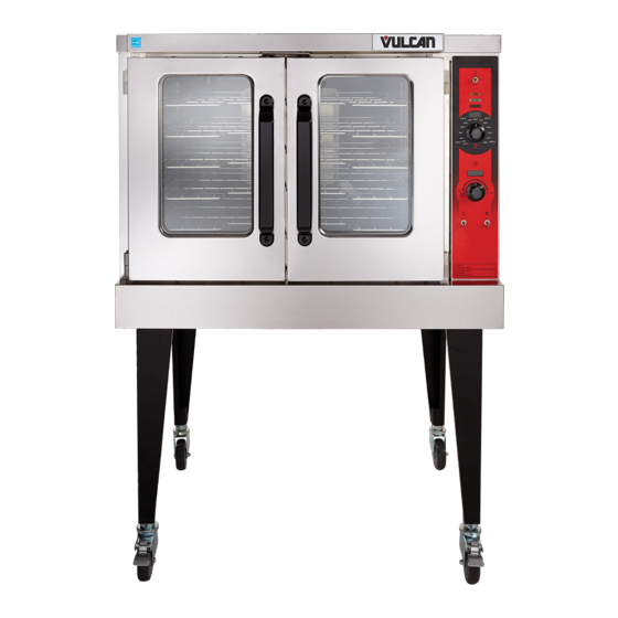
FULL SIZE GAS CONVECTION
OVEN
VC5GD
- NOTICE -
3600 North Point Blvd Baltimore, MD 21222
F45598 (0616)
Advertisement
Table of Contents

Related Manuals for Vulcan-Hart VC5GD


Summary of Contents for Vulcan-Hart VC5GD
- Page 1 ITW FEG, and by accepting this manual you agree that you will return it to ITW FEG promptly upon its request for such return at any time in the future. A product of Vulcan-Hart 3600 North Point Blvd Baltimore, MD 21222 F45598 (0616)
-
Page 2: Table Of Contents
FULL SIZE GAS CONVECTION OVEN TABLE OF CONTENTS GENERAL ....................3 INTRODUCTION . -
Page 3: General
INTRODUCTION Models FEATURES TEMPERATURE DOORS MODEL CAVITY DEPTH CONTROL (50/50) VC5GD 26.5" Solid State Independent Simultaneous doors are optional (with or w/o window). Stainless steel doors with window (standard). OPERATION LUBRICATION Refer to Operator's manual for operation instructions Refer to Lubrications Manual F20067 for current (F31123), located on Vulcan Resource Center. -
Page 4: Tools
FULL SIZE GAS CONVECTION OVEN - GENERAL TOOLS Standard • Standard set of Hand Tools. • VOM with minimum of NFPA-70E CATIII 600V, UL/CSA/TUV listed. Sensitivity of at least 20,000 ohms per volt and the ability to measure DC micro amps. Meter leads must also be rated at CAT III 600V. -
Page 5: Removal And Replacement Of Parts
FULL SIZE GAS CONVECTION OVEN - REMOVAL AND REPLACEMENT OF PARTS REMOVAL AND REPLACEMENT OF PARTS Remove screws along right side and bottom of COVERS AND PANELS front panel. Disconnect the electrical power to the machine and follow lockout / tagout procedures. Bottom Front Cover Remove four screws, two from each side of bottom cover, then remove cover from oven. -
Page 6: Control Panel Components
FULL SIZE GAS CONVECTION OVEN - REMOVAL AND REPLACEMENT OF PARTS Control Panel Remove three screws on the right side which secure the control panel then left up and pull away. Fig. 4 Slide right side rear panel up and to the right to remove. -
Page 7: Component Panel Components
FULL SIZE GAS CONVECTION OVEN - REMOVAL AND REPLACEMENT OF PARTS TEMPERATURE PROBE Disconnect the electrical power to the machine and follow lockout / tagout procedures. Remove RIGHT SIDE PANEL. NOTE: If right side - front panel is not accessible, this component can be serviced by removing CONTROL PANEL. -
Page 8: Gas Burner
FULL SIZE GAS CONVECTION OVEN - REMOVAL AND REPLACEMENT OF PARTS Fig. 11 Remove screws securing the burner cover and Fig. 9 pull straight out. Remove probe by pushing it through the oven wall opening (2, Fig. 8) in control panel area. Reverse the procedure to install the replacement probe. -
Page 9: Gas Orifice
FULL SIZE GAS CONVECTION OVEN - REMOVAL AND REPLACEMENT OF PARTS NOTE: if right side panel is not accessible, this GAS ORIFICE component can be serviced by just removing CONTROL PANEL. Disconnect lead wires. Disconnect the Disconnect compression fittings to valve. electrical power to the machine and follow lockout / tagout procedures. -
Page 10: Ignition Control Module
FULL SIZE GAS CONVECTION OVEN - REMOVAL AND REPLACEMENT OF PARTS NOTE: Clean pipe threads and apply pipe joint SPARK IGNITER AND FLAME compound to threads. Any pipe joint compound used, SENSE must be resistant to the action of propane gases. All gas joints disturbed during servicing must be checked for leaks. -
Page 11: Blower
FULL SIZE GAS CONVECTION OVEN - REMOVAL AND REPLACEMENT OF PARTS BLOWER Disconnect the electrical power to the machine and follow lockout / tagout procedures. Shut off the gas before servicing the unit. Removal Remove racks. Lay cardboard on bottom of oven cavity to protect surface. -
Page 12: Motor
FULL SIZE GAS CONVECTION OVEN - REMOVAL AND REPLACEMENT OF PARTS MOTOR Disconnect the electrical power to the machine and follow lockout / tagout procedures. Shut off the gas before servicing the unit. Remove BLOWER. Remove nuts (1, Fig. 24) that secure the motor mounting plate to rear wall. -
Page 13: Door Switch
FULL SIZE GAS CONVECTION OVEN - REMOVAL AND REPLACEMENT OF PARTS DOOR SWITCH Disconnect the electrical power to the machine and follow lockout / tagout procedures. Remove BOTTOM FRONT COVER. Unscrew nut holding door switch. Pull door switch and washer out through bottom panel opening. -
Page 14: Roller Latch Assembly (Independent Doors)
FULL SIZE GAS CONVECTION OVEN - REMOVAL AND REPLACEMENT OF PARTS Reverse procedure to install the replacement ROLLER LATCH ASSEMBLY door. (INDEPENDENT DOORS) Check oven for proper operation. HIGH LIMIT THERMOSTAT Disconnect the electrical power to the machine and follow lockout / tagout procedures. Disconnect the electrical power to the machine and Remove screws that attach roller latch assembly... -
Page 15: Interior Lights
FULL SIZE GAS CONVECTION OVEN - REMOVAL AND REPLACEMENT OF PARTS INTERIOR LIGHTS Disconnect the electrical power to the machine and follow lockout / tagout procedures. Do not touch the Halogen lamp with bare hands. If lamp is exposed to oil from the skin, the life will be reduced. - Page 16 FULL SIZE GAS CONVECTION OVEN - REMOVAL AND REPLACEMENT OF PARTS Fig. 35 Loosen tab screw holding fan to component panel. Rotate tab so that fan will clear and remove fan. Reverse procedure to install fan and check for proper operation. NOTE: Fan must be installed so air is pulled from outside the rear of oven and blown into control area.
-
Page 17: Service Procedures And Adjustments
FULL SIZE GAS CONVECTION OVEN - SERVICE PROCEDURES AND ADJUSTMENTS SERVICE PROCEDURES AND ADJUSTMENTS Remove temperature control knob. TEMPERATURE CONTROL CALIBRATION Certain procedures in this section require electrical test or measurements while power is applied to the machine. Exercise extreme caution at all times and follow Arc Flash procedures. -
Page 18: Solid State Temperature Control Test
FULL SIZE GAS CONVECTION OVEN - SERVICE PROCEDURES AND ADJUSTMENTS Push “+” or “-“ button to increase or NOTE: If right side panel is not accessible, this decrease offset. component can be serviced by removing CONTROL PANEL. NOTE: Each press will change offset by 5 degrees. Place a thermocouple in the geometric center of NOTE: After 5 seconds of no activity controller will oven cavity. -
Page 19: Temperature Probe Test
FULL SIZE GAS CONVECTION OVEN - SERVICE PROCEDURES AND ADJUSTMENTS Remove plug from manifold pressure port (1, Fig. TEMPERATURE PROBE TEST 37). Certain procedures in this section require electrical test or measurements while power is applied to the machine. Exercise extreme caution at all times and follow Arc Flash procedures. -
Page 20: Verification Of Spark At Ignitor
FULL SIZE GAS CONVECTION OVEN - SERVICE PROCEDURES AND ADJUSTMENTS • If incoming pressure to valve is between 6” W.C. It is critical that the cable be held and 14” for Natural gas and manifold pressure is 3/16" away from surface of oven frame or sparking not maintaining 5”... -
Page 21: Door Strike Adjustment Independent Doors)
FULL SIZE GAS CONVECTION OVEN - SERVICE PROCEDURES AND ADJUSTMENTS Fig. 40 Fig. 42 Open and close doors several times while observing roller latch and strike plate operation. Replace ROLLER LATCH ASSEMBLY (INDEPENDENT DOORS) if malfunctioning. Each oven door should open with a force of 8 to 25 pounds when pulled at the handle. -
Page 22: Electrical Operation
Temperature Control the heat relay (R3) through the blower motor centrifugal switch contacts. (VC5GD) ....High Limit Protects the oven from temperatures above 550°F by removing power from the 1st valve Thermostat . -
Page 23: Component Location
FULL SIZE GAS CONVECTION OVEN - ELECTRICAL OPERATION COMPONENT LOCATION Fig. 43 Page 23 of 35 F45598 (0616) - Page 24 FULL SIZE GAS CONVECTION OVEN - ELECTRICAL OPERATION CONTROL PANEL ON/ OFF / COOL Switch ON / HEAT / RESET Lights Temperature Dial Digital Time Readout Timer HI / LOW Fan Setting Light ON / OFF Switch Temperature Control Board Timer Board Light and Fan Speed Switch Board CONTROL PANEL DIGITAL TEMPERATURE READOUT...
- Page 25 FULL SIZE GAS CONVECTION OVEN - ELECTRICAL OPERATION Fig. 44 CONTROL PANEL DIGITAL TIME READOUT Page 25 of 35 F45598 (0616)
- Page 26 FULL SIZE GAS CONVECTION OVEN - ELECTRICAL OPERATION Fig. 45 F45598 (0616) Page 26 of 35...
- Page 27 FULL SIZE GAS CONVECTION OVEN - ELECTRICAL OPERATION Fig. 46 OVEN CAVITY Blower Plate and Fan Baffle Door Seal Door Switch Page 27 of 35 F45598 (0616)
-
Page 28: Sequence Of Operation
FULL SIZE GAS CONVECTION OVEN - ELECTRICAL OPERATION Fig. 47 TOP VIEW INSIDE OVEN Blower Motor Burner Assembly and Gas Lines (underneath lower oven cavity) Temperature Probe Light Power switch (S1) OFF. SEQUENCE OF OPERATION Temperature dial set to lowest temperature (fully Counter-Clockwise). - Page 29 FULL SIZE GAS CONVECTION OVEN - ELECTRICAL OPERATION Oven cavity temperature below 140°F. Second valve (main) on gas valve is energized. Gas starts to flow to Set temperature control dial to desired burner, sparking begins, the temperature. burner lights. Sparking continues Power switch (S1) turned ON.
- Page 30 FULL SIZE GAS CONVECTION OVEN - ELECTRICAL OPERATION Conditions. Oven is ON. Oven cavity temperature needs to be lowered. Doors are open (door switch contacts OPEN). Fan speed switch (S2) set to "Hi". Power Switch (S1) turned to COOL DOWN. Power ON light (Amber) goes out.
-
Page 31: Diagrams
11 x 17 Size • VC5GD WIRING DIAGRAM • VC5GD SCHEMATIC VC5GD GAS CONVECTION OVEN WIRING DIAGRAM Fig. 48 LEGEND FOR VC5GD GAS CONVECTION OVEN WIRING DIAGRAM ASSY, TEMP. CONTROL BOARD ASSY, TIMER BOARD Page 31 of 35 F45598 (0616) - Page 32 FULL SIZE GAS CONVECTION OVEN - DIAGRAMS LEGEND FOR VC5GD GAS CONVECTION OVEN WIRING DIAGRAM ASS, SWITCH BOARD LCOG REAR WIRED SET (SEE NOTE) LCOG ACTUATOR HARNESS LCOG SENSING HARNESS LCOG MOTOR WIRE SET LCOG DOOR SWITCH, 2HP, 250F BLOCK, PORCELAIN ASSEMBLY MOTOR 2 SPEED G.E.
- Page 33 FULL SIZE GAS CONVECTION OVEN - DIAGRAMS Fig. 49 Page 33 of 35 F45598 (0616)
-
Page 34: Troubleshooting
FULL SIZE GAS CONVECTION OVEN - TROUBLESHOOTING TROUBLESHOOTING ALL MODELS Certain procedures in this section require electrical test or measurements while power is applied to the machine. Exercise extreme caution at all times and follow Arc Flash procedures. If test points are not easily accessible, disconnect power and follow Lockout/Tagout procedures, attach test equipment and reapply... -
Page 35: Vulcan
FULL SIZE GAS CONVECTION OVEN - TROUBLESHOOTING SYMPTOMS POSSIBLE CAUSES Igniter lead connections malfunction. Ignitor ground inoperative. Ignitor/flame sense malfunction. Gas ignites but will not maintain flame. Insufficient gas pressure. Snorkel vent plugged, obstructed or missing. Incorrect polarity from transformer to Ignition module.
Need help?
Do you have a question about the VC5GD and is the answer not in the manual?
Questions and answers