Vulcan-Hart VC4EC Service Manual
Vc4e & vc6e series full size electric convection ovens
Hide thumbs
Also See for VC4EC:
- Specifications (2 pages) ,
- Service manual (64 pages) ,
- Installation and operation manual (16 pages)
Table of Contents
Advertisement
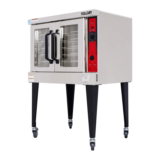
VC4ED SHOWN
This Manual is prepared for the use of trained Vulcan Service
Technicians and should not be used by those not properly qualified.
If you have attended a Vulcan Service School for this product, you
may be qualified to perform all the procedures described in this
manual.
This manual is not intended to be all encompassing. If you have not
attended a Vulcan Service School for this product, you should read,
in its entirety, the repair procedure you wish to perform to
determine if you have the necessary tools, instruments and skills
required to perform the procedure. Procedures for which you do not
have the necessary tools, instruments and skills should be
performed by a trained Vulcan Service Technician.
Reproduction or other use of this Manual, without the express
written consent of Vulcan, is prohibited.
A product of VULCAN-HART
SERVICE MANUAL
VC4E & VC6E
ELECTRIC CONVECTION
MODEL
VC4ES
VC4ED
VC4EC
VC6ES
VC6ED
VC6EC
- NOTICE -
SERIES
FULL SIZE
OVENS
ML
126743
126744
126745
126746
126747
126748
LOUISVILLE, KY 40201-0696
F25105 (Rev. A, October 2007)
Advertisement
Table of Contents

Related Manuals for Vulcan-Hart VC4EC


Summary of Contents for Vulcan-Hart VC4EC
- Page 1 This Manual is prepared for the use of trained Vulcan Service Technicians and should not be used by those not properly qualified. If you have attended a Vulcan Service School for this product, you may be qualified to perform all the procedures described in this manual.
-
Page 2: Table Of Contents
Oven Doors and Bearings (Independent Doors) ........ - Page 3 VC4EC, VC6EC Computer Control, 208-240V (Roast & Hold Standard) ......41 VC4EC, VC6EC Computer Control, 480V (Roast & Hold Standard) ......42 Wiring Diagrams .
-
Page 4: General
CAVITY TEMPERATURE DEPTH CONTROL 26.5" Mechanical (KX) VC4ES VC4ED 26.5" Solid State 26.5" Computer VC4EC VC6ES 30.5" Mechanical (KX) 30.5" Solid State VC6ED VC6EC 30.5" Computer 1. Simultaneous doors are optional (with or w/o window). NOTES: 2. Stainless steel doors w/o window (standard). -
Page 5: Specifications
SPECIFICATIONS Electrical MODEL VC4ES VC4ED VC4EC VC6ES VC6ED VC6EC NOTES: MODEL VC4ES VC4ED VC4EC VC6ES VC6ED VC6EC NOTES: AMPERAGE - 3 PHASE/ 60HZ TOTAL POWER PER LINE (KW) 208V 240V 480V 12.5 1. Amperage values in the table are nominal. Tolerance is +5/-10%. -
Page 6: Removal And Replacement Of Parts
F25105 (Rev. A, October 2007) NOTE: If the oven has a mechanical (KX type) thermostat, it must be removed from the control panel first, before removing the control panel. -
Page 7: Control Panel Components
Removable Components Remove the control panel as outlined under COVERS AND PANELS. Remove the component being replaced. Reverse the procedure to install the replacement component, then check oven for proper operation. Page 7 of 60 F25105 (Rev. A, October 2007) -
Page 8: Component Panel Components
COVERS AND PANELS. Disconnect the wire leads to the component being replaced. Remove the component. Reverse the procedure to install the replacement component and check oven for proper operation. F25105 (Rev. A, October 2007) TEMPERATURE PROBE (SOLID STATE CONTROL) Remove the right side panel as outlined under COVERS AND PANELS. -
Page 9: Heating Elements
Remove probe by pushing it through the oven wall and into the control panel area. NOTE: The hole in the oven cavity wall does not line up straight with the oven cavity outer shell, therefore the probe must be removed at an angle. -
Page 10: Blower And Motor
Check for proper operation. Alternate Access If the heating element is not removing easily from inside the oven cavity, and access to the left side panel and/or the top panel is available, this alternate removal method may be used. NOTE: On stacked ovens, if the bottom oven is... -
Page 11: Door Switch
13. Position motor mounting plate on the rear wall and secure with nuts and washers. 14. Replace the baffle panel. 15. Remove cardboard from the bottom of the oven cavity. 16. Check oven for proper operation then replace rack guides and racks. -
Page 12: Door Window
Reverse procedure to install the replacement window. OVEN DOORS AND BEARINGS (INDEPENDENT DOORS) Remove the top front cover and bottom front cover as outlined under COVERS AND PANELS. -
Page 13: Oven Doors (Simultaneous Doors)
Reverse procedure to install door assembly and check for proper adjustment as outlined under DOOR ADJUSTMENT and DOOR SWITCH ADJUSTMENT in SERVICE PROCEDURES AND ADJUSTMENTS. OVEN DOORS (SIMULTANEOUS DOORS) Assembly Removal Remove the top front cover and bottom front cover as outlined under COVERS AND PANELS. -
Page 14: Roller Latch Assembly
DOOR SWITCH ADJUSTMENT in SERVICE PROCEDURES AND ADJUSTMENTS. Disassembly Remove the door assembly as outlined in OVEN DOORS (SIMULTANEOUS) under ASSEMBLY REMOVAL. Remove the door chain by loosening one of the turnbuckles. Loosen the set screw on the sprocket of door being replaced. -
Page 15: Mechanical (Kx) Thermostat
NOTE: The hole in the oven cavity wall does not line up straight with the oven cavity outer shell, therefore the probe must be removed at an angle. -
Page 16: Interior Lights
Remove the socket from the oven. Attach the lead wires to the replacement socket. Insert the socket into the hole in the oven and push until the socket is held in place by the retaining tabs. Install the light bulb and lens. -
Page 17: Service Procedures And Adjustments
Set the power switch to ON. Set the temperature control dial to 350 °F. Allow the oven temperature to stabilize (normally 3 cycles). Record the temperature at which the Heat lamp goes OFF and comes ON for at least two complete heating cycles. -
Page 18: Mechanical (Kx) Thermostat Calibration
Replace the knob and verify the setting is still at 350°F. Repeat step 7 until the average temperature is within tolerance. NOTE: Allow the oven to cycle at least two times between adjustments before performing the calculation. After the final adjustment is made and the... -
Page 19: Solid State Temperature Control Test
COVERS AND PANELS. Place a thermocouple in the geometric center of the oven cavity. NOTE: Oven temperature must be below 450°. Set the temperature control to the maximum setting. Check machine data plate for correct voltage to oven. -
Page 20: Temperature Probe Test (Solid State Control)
The following steps require power to be applied to the unit during the test. Use extreme caution at all times. Turn the power switch ON and set the oven temperature control to the highest setting. Measure the voltage at the heating element terminals and verify it against the data plate voltage. -
Page 21: Blower Adjustment
BLOWER ADJUSTMENT Remove the blower motor and mounting assembly by following steps 1 through 7 as outlined under BLOWER AND MOTOR in REMOVAL AND REPLACEMENT OF PARTS. Loosen the motor mounting bolts. Adjust the motor position until the blower is parallel to and 1/4 inch away from the motor mounting plate. Check for squareness of the blower to the motor mounting plate at the top, bottom, left and right of the blower. -
Page 22: Door Adjustment
ROLLER LATCH ASSEMBLY (INDEPENDENT DOORS) and adjust as outlined in this procedure. Each oven door should open with a force of 8 to 25 pounds when pulled at the handle. The adjustments must allow the doors to remain closed during normal operation and allow opening without exertion by the user. -
Page 23: Door Catch Roller Adjustment (Independent Doors)
Repeat step 6 thru this step. DO NOT BEND THE DOOR STRIKE. Each oven door should open with a force of 8 to 25 pounds when pulled at the handle. See TOOLS under GENERAL. -
Page 24: Door Switch Adjustment
1/2" from being closed. If adjustment is necessary, bend the switch actuator to obtain the proper setting. Install the top front cover. Apply power to the oven and check for proper operation. F25105 (Rev. A, October 2007) DOOR CHAIN ADJUSTMENT (SIMULTANEOUS DOORS) -
Page 25: Computer Control
Exit Setup Mode and return to Operation Mode. Probe Test If the oven is not heating or displaying the proper temperature, the temperature probe may be malfunctioning. Determine if the probe is good or causing the operational problem. Temporarily, disconnect the existing probe lead wires from the computer control and connect the lead wires from a known good "J"... -
Page 26: Computer Control Temperature Calibration
Press the set key then temperature key to enter the temperature set mode. The display will alternate between the term "StPt" (set point) and the current oven temperature setting. Press the up or down arrow keys to make the proper selection. -
Page 27: Computer Control Operational Test
5°F tolerance. Exit the setup mode. Allow the oven to cycle at least two times between adjustments. If the temperature variance still differs more than 5°F from the set point, verify the correct calibration offset value was entered and retained. - Page 28 NOTE: If the control was calling for heat when the calibration mode was entered, heating will resume after exiting the test mode. Press the Rack 1 key to accept the default "no" under the "CALY" (calibrate) parameter and advance the display menu to the "LgOt" (logic output) test.
-
Page 29: Electrical Operation
Cook Timer ....Counts the "Cook" time of the product and signals the buzzer at the end of Door Switch ....Allows the oven to operate when the doors are closed but stops the oven Blower Motor . -
Page 30: Component Location
KX thermostat ....Regulates the oven cavity temperature by controlling 2CON to energize the Cooling Fan ....Circulates cooler air from outside the oven to cool components in the Fuses . - Page 31 FULL SIZE ELECTRIC CONVECTION OVENS - ELECTRICAL OPERATION VC4ES/6ES with Mechanical KX thermostat - Plug, Socket and Components Page 31 of 60 F25105 (Rev. A, October 2007)
- Page 32 FULL SIZE ELECTRIC CONVECTION OVENS - ELECTRICAL OPERATION VC4ED/6ED with Solid State Control - Plug, Socket and Components F25105 (Rev. A, October 2007) Page 32 of 60...
- Page 33 FULL SIZE ELECTRIC CONVECTION OVENS - ELECTRICAL OPERATION VC4EC/6EC - Plug, Socket and Components (Cook & Hold Standard) Page 33 of 60 F25105 (Rev. A, October 2007)
-
Page 34: Sequence Of Operation
NOTE: Motor speed (Hi/Low) depends on position of fan speed switch (S3). Component cooling fan energized. Power to oven cavity light switch (S3) wire #1. Turns cavity lights ON/OFF and does not affect "Cook" cycle. Set thermostat to desired "Cook" temperature and thermostat CLOSES. -
Page 35: Cool Down Cycle (Kx Thermostat Or Solid State Control)
The oven will remain in this condition until the power switch (S1) is turned to the OFF or ON position. VC4EC, VC6EC (Computer Control) Schematic diagram 6536 will be used to explain the electrical sequence of operation or both the "Cook"... -
Page 36: Temperature And Time Cycle (Cooking)
Oven "Heat Light" on the control goes out. Oven "Ready Light" on the control comes Electronic beeper sounds momentarily. The oven will continue to cycle on the computer control until the doors are opened or power switch (S1) is turned to the OFF or COOL DOWN position. -
Page 37: Schematics
FULL SIZE ELECTRIC CONVECTION OVENS - ELECTRICAL OPERATION SCHEMATICS VC4ES, VC6ES with Mechanical (KX) Controls, 208-240V Page 37 of 60 F25105 (Rev. A, October 2007) -
Page 38: Vc4Es, Vc6Es With Mechanical (Kx) Controls, 480V
FULL SIZE ELECTRIC CONVECTION OVENS - ELECTRICAL OPERATION VC4ES, VC6ES with Mechanical (KX) Controls, 480V F25105 (Rev. A, October 2007) Page 38 of 60... -
Page 39: Vc4Ed, Vc6Ed With Solid State Temperature Control, 208-240V
FULL SIZE ELECTRIC CONVECTION OVENS - ELECTRICAL OPERATION VC4ED, VC6ED with Solid State Temperature Control, 208-240V Page 39 of 60 F25105 (Rev. A, October 2007) -
Page 40: Vc4Ed, Vc6Ed With Solid State Temperature Control, 480V
FULL SIZE ELECTRIC CONVECTION OVENS - ELECTRICAL OPERATION VC4ED, VC6ED with Solid State Temperature Control, 480V F25105 (Rev. A, October 2007) Page 40 of 60... -
Page 41: Vc4Ec, Vc6Ec Computer Control, 208-240V (Roast & Hold Standard)
FULL SIZE ELECTRIC CONVECTION OVENS - ELECTRICAL OPERATION VC4EC, VC6EC Computer Control, 208-240V (Roast & Hold Standard) Page 41 of 60 F25105 (Rev. A, October 2007) -
Page 42: Vc4Ec, Vc6Ec Computer Control, 480V (Roast & Hold Standard)
FULL SIZE ELECTRIC CONVECTION OVENS - ELECTRICAL OPERATION VC4EC, VC6EC Computer Control, 480V (Roast & Hold Standard) F25105 (Rev. A, October 2007) Page 42 of 60... - Page 43 FULL SIZE ELECTRIC CONVECTION OVENS - ELECTRICAL OPERATION THIS PAGE PURPOSELY LEFT BLANK Page 43 of 60 F25105 (Rev. A, October 2007)
-
Page 44: Wiring Diagrams
FULL SIZE ELECTRIC CONVECTION OVENS - ELECTRICAL OPERATION WIRING DIAGRAMS VC4ES, VC6ES with Mechanical (KX) Control, 208-240V F25105 (Rev. A, October 2007) Page 44 of 60... - Page 45 FULL SIZE ELECTRIC CONVECTION OVENS - ELECTRICAL OPERATION Page 45 of 60 F25105 (Rev. A, October 2007)
-
Page 46: Vc4Es, Vc6Es With Mechanical (Kx) Control, 480V
FULL SIZE ELECTRIC CONVECTION OVENS - ELECTRICAL OPERATION VC4ES, VC6ES with Mechanical (KX) Control, 480V F25105 (Rev. A, October 2007) Page 46 of 60... - Page 47 FULL SIZE ELECTRIC CONVECTION OVENS - ELECTRICAL OPERATION Page 47 of 60 F25105 (Rev. A, October 2007)
-
Page 48: Vc4Ed, Vc6Ed With Solid State Temperature Control, 208-240V
FULL SIZE ELECTRIC CONVECTION OVENS - ELECTRICAL OPERATION VC4ED, VC6ED with Solid State Temperature Control, 208-240V F25105 (Rev. A, October 2007) Page 48 of 60... - Page 49 FULL SIZE ELECTRIC CONVECTION OVENS - ELECTRICAL OPERATION Page 49 of 60 F25105 (Rev. A, October 2007)
-
Page 50: Vc4Ed, Vc6Ed With Solid State Temperature Control, 480V
FULL SIZE ELECTRIC CONVECTION OVENS - ELECTRICAL OPERATION VC4ED, VC6ED with Solid State Temperature Control, 480V F25105 (Rev. A, October 2007) Page 50 of 60... - Page 51 FULL SIZE ELECTRIC CONVECTION OVENS - ELECTRICAL OPERATION Page 51 of 60 F25105 (Rev. A, October 2007)
-
Page 52: Vc4Ec, Vc6Ec Computer Control, 208-240V (Roast & Hold Standard)
FULL SIZE ELECTRIC CONVECTION OVENS - ELECTRICAL OPERATION VC4EC, VC6EC Computer Control, 208-240V (Roast & Hold Standard) F25105 (Rev. A, October 2007) Page 52 of 60... - Page 53 FULL SIZE ELECTRIC CONVECTION OVENS - ELECTRICAL OPERATION Page 53 of 60 F25105 (Rev. A, October 2007)
-
Page 54: Vc4Ec, Vc6Ec Computer Control, 480V (Roast & Hold Standard)
FULL SIZE ELECTRIC CONVECTION OVENS - ELECTRICAL OPERATION VC4EC, VC6EC Computer Control, 480V (Roast & Hold Standard) F25105 (Rev. A, October 2007) Page 54 of 60... - Page 55 FULL SIZE ELECTRIC CONVECTION OVENS - ELECTRICAL OPERATION Page 55 of 60 F25105 (Rev. A, October 2007)
-
Page 56: Troubleshooting
Blower motor doesn’t run with power switch "ON", but oven heats. Blower motor doesn’t run in "Cool Down", but runs ok in "ON" position. Excessive or low heat in oven. Mechanical Timer inoperative or not functioning properly. Component cooling Fan does not run. -
Page 57: Computer Control Models Only
SYMPTOMS No power to oven controls. No heat, convection fan motor runs. No power to temperature control. Door does not seal or shut properly COMPUTER CONTROL MODELS ONLY SYMPTOM Oven does not heat. High limit thermostat shutting OFF heat. Oven not hot enough. - Page 58 In the display window, the error code will alternate between the code and the oven cavity temperature or dashes if the oven is calling for heat (heat light on). The exact error code displayed will depend on the priority assigned to the problem in the EPROM'S software.
- Page 59 FULL SIZE ELECTRIC CONVECTION OVENS - TROUBLESHOOTING - N O T E S - Page 59 of 60 F25105 (Rev. A, October 2007)
- Page 60 FULL SIZE ELECTRIC CONVECTION OVENS F25105 (Rev. A, October 2007) Printed in U.S.A.
Need help?
Do you have a question about the VC4EC and is the answer not in the manual?
Questions and answers