
Related Manuals for Elvox 5721


Summary of Contents for Elvox 5721
- Page 1 Installer Manual Art. 5721 - 5721/D* Video door entry unit with 3.5" monitor for Due Fili (Two-Wire) call system Elvox Vimar Group.
-
Page 3: Table Of Contents
Table of Contents Technical characteristics …………………………………………………………………………………………………………… Type of system ………………………………………………………………………………………………………………… Advantages of the Due Fili (Two-Wire) system …………………………………………………………………………… Main technical characteristics of the system ………………………………………………………………………………… Description of terminals ……………………………………………………………………………………………………… Power consumption …………………………………………………………………………………………………………… Power supplies and other Due Fili (Two-Wire) accessories ……………………………………………………………… Functions of the video door entry unit ……………………………………………………………………………………... - Page 4 Indice Resetting configurations ……………………………………………………………………………………………………………… 62 Integrating the video door entry unit with the By-me system ………………………………………………………………… 63 Installation rules and regulatory compliance ………………………………………………………………………………… 63 …………………………………………………………………………………………………………………………… 64 Glossary...
-
Page 5: Technical Characteristics
Type of system. The video door entry unit 5721 can be used only in Due Fili (Two-Wire) video door entry systems; it is therefore necessary to use only devices in the Due Fili (Two-Wire) range (for the specifications please see the relevant manuals). -
Page 6: Main Technical Characteristics Of The System
• Advanced device programming with a personal computer (PC), USB interface 692I/U and "EVCom" software. Description of terminals. On the back of the video door entry unit 5721 there are 3 types of connectors: - Removable 8-pin terminal block to connect the bus and other optional inputs and outputs; these terminals, divided according to the functions described in the table below, are used to make all the connections from and to the video door entry unit. -
Page 7: Power Consumption
Technical characteristics Power consumption. The consumption of the video door entry unit 5721 depends on the device's current mode of operation (with or without a call in progress). The mean values of the power input in the typical modes of operation are the following: •... - Page 8 * Hearing aid function (art. 5721/D only) Art. 5721/D has an internal coil which allows hearing aid wearers to use the device. For an effective magnetic coupling between the monitor and the hearing aid, it is advisable to stand facing the monitor.
-
Page 9: Functions Of The Video Door Entry Unit
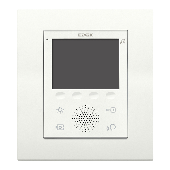
- With the MONITOR ON (the display and the LEDs for backlighting the buttons are on). - With the MONITOR OFF (both the display and the LEDs for backlighting the buttons are switched off). Figure 2 - Front view 5721. -
Page 10: Selecting The "Tv" (Video Termination) Line Termination
Functions of the video door entry unit Selecting the "TV" (Video Termination) line termination The bus line must be adjusted according to the cable used (impedance) and the installation topology of the system. It is possible to use a twisted-pair cable at 100 Ω or a cable Cat. 5 (50 Ω). The "TV video termination"... -
Page 11: Warnings For Device Coding And Programming
Functions of the video door entry unit Warnings for device coding and programming. The identification phase (coding via numerical identification - ID) for some devices of the Due Fili (Two-Wire) system is done during the programming phase while for others it is done with jumpers or dip-switches in the device and that must be set during the phase of installation (see the instruction sheets of the single devices). -
Page 12: Answering Calls
Functions of the video door entry unit Answering calls. When a call is made from a speech unit (external panel, intercom or consumer unit), the device related to the called numerical identification modulates the call tone configured on the speaker; the video door entry unit then emits an audible warning and, if there is also the video signal (that is, for instance, there is an audio/video panel), the display will switch on to show the person making the call. -
Page 13: Self-Start Function
Functions of the video door entry unit Self-Start function. This function is used to enable audio and video communication on the Master panel without a call being re- ceived; this can be useful, for example, if you want to check the outside area or one or more interior areas where additional video cameras are installed. -
Page 14: Door Open" Indicator
Functions of the video door entry unit “Door Open” indicator. This function shows you a warning icon at the top right corner of the display telling you that a door or gate has remained open; this application is useful, for example, to signal any unwanted entry into the dwelling. To enable this function, you must connect a sensor with N.O. -
Page 15: Activating Lock Control
+12V +12V Figure 9 - Electric lock 12Vdc 200mA max Figure 10 - Electric lock 15Vac 2A max AL - Elvox power supply Art. 832/030 TE - External video panel RL - Relay Art. 0170/001 CP - Lock open button... -
Page 16: Activating Stairs Lights Control
Functions of the video door entry unit Activating stairs lights control. With this command it is possible to activate the output used for commanding a suitable external relay connect- ed to one or more lamps to be turned on. The control is activated by tapping the softkey E of the video door entry unit; this control is always active in both operating states of MONITOR OFF and MONITOR ON respectively. -
Page 17: Activating Auxiliary Functions
Example installation CP - N.O. call button VV - Video door entry unit 5721 Figure 12 - Doorbell calls... -
Page 18: Landing Calls
Montante Alimentatore 20577/19577/14577 Targa principale AL - Power supply Art. 6922 SP - Separator Art. 692S CP - Landing call button Art. 20577/19577/14577 NT - Network VV - Video door entry unit 5721 Figure 13 - Landing calls, audio only... - Page 19 SP - Separator Art. 692S CP - Landing call button Art. 20577/19577/14577 TC - Video camera with microphone Art. 20565/19565/14565 VV - Video door entry unit 5721 Figure 14 - Landing calls, audio/video NT - Network For further details on the connections, see the technical documentation of the single articles (call button, video...
-
Page 20: Installation Of Supplementary External Ringtones
If you install 12 Vdc relays (for instance, art. 0170/101) the "+12" and "CH" terminals of the video door entry unit and, if you use the Elvox ringtone 860A powered from the mains, the terminals to be wired are "CH" and "M". - Page 21 Video door entry units with simultaneous Figure 18 - Video door entry units with active video calls distributor AL1 - Power supply Art. 6923 AL2 - Power supply Art. 6922 M - Pillar NT - Network VV - Video door entry unit 5721...
-
Page 22: Installation Topology
AL - Power supply Art. 6922 TE - External video panel K - Landing call button SE - Electric lock 12 Vdc VV - Video door entry unit 5721 Figure 19 - Video door entry system with 1 indoor station... - Page 23 K - Landing call button CV - Audio door entry unit Art. 20557/19557/14557 VV - Video door entry unit 5721 Figure 20 - Multi-family video door entry system In the above examples, there is a single main power supply (AL) in the systems that use the single speech unit (TE).
- Page 24 Installation topology In the system pillar there can be installed both Vimar and Elvox (VV, VE, CE) indoor stations, provided that these belong solely to the Due Fili (Two-Wire) system range. For the technical details on the possible installation topologies in both basic residential and complex building structures, please see the examples shown in the diagrams.
- Page 25 AL - Power supply Art. 6922 AS - Additional power supply Art. 6582 for LED power supply CE - Elvox audio door entry unit Art. 6209 DV - Video distributor Art. 692D SP - Separator Art. 692S TE - External video panel VE - Elvox video door entry unit Art.
-
Page 26: Configuring The Video Door Entry Unit
Confi guration of the video door entry unit Configuration of the video door entry unit. All the main standard functions of the video door entry unit are configured with the buttons on the front of the device. For the advanced programming of the video door entry unit (optional functions such as setting groups, association with the landing audio/video call buttons, etc.) it is necessary to use the PC, USB interface 692I/U, “EVCom”... -
Page 27: Landing Calls, Audio/Video
Confi guration of the video door entry unit Landing calls, audio/video. If there is a speech unit on the landing with the audio/video function (art. 20577/19577/14577 with 20560/19560/14560 or 20565/19565/14565), the video door entry unit must be configured for being able to receive the audio communication from the call button 20577/19577/14577 and activation of the video camera from the landing. - Page 28 Figure 24 - Landing calls, audio/video AL - Power supply Art. 6922 AS - Additional power supply Art. 6582 CE - Elvox audio door entry unit Art. 6209 SP - Separator Art. 692S TA - Elvox audio external panel series 1300 IF - Audio/video interface for video cameras Art.
-
Page 29: Audio/Video Interface For Video Cameras
Confi guration of the video door entry unit Audio/video interface for video cameras. The audio/video interface for video cameras art. 69AM is a DIN bar 8-module device necessary to make both the audio/video landing call and self-start any additional video cameras installed in the system with a “CCTV function”. - Page 30 Confi guration of the video door entry unit N.B.: For each video door entry unit it is possible to configure the self-start sequence of the additional video cameras connected to the audio/video interface 02016; this configuration can be made exclusively with advanced programming of the audio/video interface by using the PC and the USB interface 692I/U with the “EVCom”...
- Page 31 Confi guration of the video door entry unit 2. Using the interface 69AM for audio/video landing calls. If there is a landing audio/video speech unit (push-button 20577/19577/14577 and video cameras 20560, 20565, 19560, 19565, 14560, 14565), the audio/video interface can be used instead without numerical cod- ing of the secondary panel as instead was necessary in the preceding case (in this way an ID reserved for the class of panels is not pointlessly occupied).
-
Page 32: Switching On The Video Door Entry Unit For The First Time
Confi guration of the video door entry unit Switching on the video door entry unit for the first time. When powering up the video door entry unit for the first time the monitor will display the neutral stand-by screen; tap any softkey to continue. The "Welcome"... -
Page 33: Accessing The Configuration Menu
Confi guration of the video door entry unit • On tapping the softkey C (corresponding to the icon ) you adjust the volume with the softkeys B and C (icon Figure 30 - Initialization performed The ID number is then saved by the video door entry unit and is shown in green at the top of the display (fig. 30). -
Page 34: Changing/Associating A New Id With The Video Door Entry Unit
Confi guration of the video door entry unit Figure 33 - Entering PIN digit Figure 34 - Entering PIN N.B. To access the Configuration menu it is always necessary to enter the PIN code. Once the PIN has been correctly entered the monitor will display the Configuration menu (fig. 35) Figure 35 - Configuration menu Changing/associating a new ID with the video door entry unit. -
Page 35: Secondary Id Coding For The Video Door Entry Unit
Confi guration of the video door entry unit Figure 36 - Initialization in progress Figure 37 - Initialization performed • If the panel has push-buttons, press the button that you want to associate with the video door entry unit; if instead the panel is alphanumerical, key in the number to associate and press the "bell"... -
Page 36: Changing The Pin Code
Confi guration of the video door entry unit • From the Configuration menu (fig. 35), use B and C to select the icon and tap the softkey D. The video door entry unit enters into "communication" with the panel and the initialization phase is started (fig. -
Page 37: Selecting The Type Of Ringtones
Confi guration of the video door entry unit Selecting the type of ringtones. Using the video door entry unit it is possible to select the types of ringtone to combine with the different calls that it can receive: - call from panel; - call from landing;... -
Page 38: Turning Off The Ringtone
Confi guration of the video door entry unit • Setting the intercom call tune. Using B and C, select the icon and confirm by tapping D. Fig. 47 - Selecting an intercom call Using B and C, select the desired tune and confirm by tapping D. Turning off the ringtone. -
Page 39: Adjusting The Ringtone Volume
Confi guration of the video door entry unit Ringtone volume adjustment. The volumes of the ringtones described above are adjusted in one and therefore all three will be given the same volume level. To set the volume, starting from the main screen, tap the softkey D (icon ) and using B and C select the icon ;... -
Page 40: Button Tone
Confi guration of the video door entry unit Using the softkeys B and C set the level which will be highlighted by the horizontal bar: - short pressure = single increase or decrease; - long pressure = gradually faster increase or decrease. Lastly tap D to confirm. -
Page 41: Setting The Speaker Volume
Confi guration of the video door entry unit Using the softkeys B and C enable (ON) or disable (OFF) the buttons and confirm by tapping D. Adjusting the speakerphone volume during a call. With this procedure it is possible to adjust the volume of the audio channel (voice communication) that from a speech unit is sent to the loudspeaker of the video door entry unit. -
Page 42: Associating An Icon With A Function
Confi guration of the video door entry unit Fig. 56 - Accessing the User Away function Fig. 57 - Selecting and activating the User Away function When the "User Away" function is enabled, the display shows the corresponding icon. Associating an icon with a function. This option allows you to assign a specific icon to each one of the 16 available functions. -
Page 43: Editing A Function
Confi guration of the video door entry unit Fig. 60 - Selecting the identification icon Editing a function. This option allows you to edit a previously saved function. Starting from the Configuration menu (fig. 35), use B and C to select the icon and tap the softkey D. -
Page 44: Deleting A Function
Confi guration of the video door entry unit Deleting a function. This option allows you to delete a previously saved function (which can then be reconfigured). Starting from the Configuration menu (fig. 35), use B and C to select the icon and tap the softkey D. -
Page 45: Configuring Intercom Calls
LOCK button (this applies to all models of video and audio door entry unit in the Vimar group Elvox range). Fig. 66 - Selecting another user video door entry Fig. -
Page 46: Saving Users On Already Configured Intercom Calls
Confi guration of the video door entry unit After making the association, the video door entry unit waits for the next ID to associate with the intercom call; then proceed as above or tap A to exit the menu. The number identifying the intercom call (from 1 to 9) is assigned by the video door entry unit according to those already present or according to those that may get deleted;... -
Page 47: Deleting Users Saved On Already Configured Intercom Calls
Confi guration of the video door entry unit After making the association, the video door entry unit waits for another new ID to associate with the call; then proceed as above or tap A to exit the menu. Deleting users saved on already configured intercom calls. This option allows you to delete a previously configured intercom call. -
Page 48: Warning Screens
Confi guration of the video door entry unit Warning screens. The display of the video door entry unit, in the event of a call from the consumer unit, will show the screen of fig. 74. Fig. 74 - Call from consumer unit waiting If while you are carrying out an operation with the video door entry unit the bus is momentarily "busy"... -
Page 49: Configuring The Optional Functions Of The Video Door Entry Unit (Advanced Programming With "Evcom")
The video door entry unit passes on to communication at the end of the ringtone cycle Landing Group Enables creating a Landing Group with article Elvox 6120 Lock > Master Enables Master lock opening with video door entry unit at rest Ring. - Page 50 Confi guration of the video door entry unit Fig. 77...
- Page 51 Confi guration of the video door entry unit Configuration methods for functions assigned to buttons The lock, self-start and stair light buttons can be used with their “Default configuration” or can be “reconfigured” from the Default setting. In the former instance they are used to send a lock opening command, self-start and send a stair light activation command.
- Page 52 Confi guration of the video door entry unit FUNCTION DESCRIPTION FREE No function assigned. For some buttons this corresponds to a default action DEVICE Makes an intercom call PANEL Self-start to a specific panel. If the lock button is configured in this way, the button does not activate self-start but sends the lock command to the entrance panel instead AUXILIARY Activates one of the relays for any Art.
- Page 53 Confi guration of the video door entry unit Configuration methods for functions assigned to buttons P1, … P6, “listbox” default (FREE) With a "Default" configuration (FREE) in the “listbox” (fig. 79), an icon must be assigned to each relay (acti- vation of the command from the monitor is described in the section “Activating P Function”) to activate the P functions and the corresponding relays (configured previously).
- Page 54 Confi guration of the video door entry unit Fig. 80 After activating the icons in "P menu" (figure 80), the indications referring to the activated functions will appear in the "Buttons menu" (figure 81; RELAY 1 ... RELAY 5 in the example image). Fig.
- Page 55 Confi guration of the video door entry unit Configuration methods for functions assigned to buttons P1, ... P6, "listbox recon- figuration description" The Default configuration (FREE) in the “listbox” can be modified; the “P functions” can perform “F1, F1/PANEL, F2, F2/PANEL” functions (see description in the table). Also in this case, an icon must be assigned to mark the correspondence between the Buttons menu and P menu (if, for example, P2 is modified in the “Buttons menu”...
- Page 56 Confi guration of the video door entry unit Fig. 83...
- Page 57 Confi guration of the video door entry unit Configuration methods for functions assigned to buttons P7, ... P16 Functions P7 to P16 cannot be configured but can still be activated; also in this case, an icon must be assigned to mark the correspondence between the Buttons menu and P menu. Fig.
-
Page 58: Intercom Calls
Confi guration of the video door entry unit Intercom calls The monitor can be programmed with a list of 9 intercom calls. A tenth is added automatically if the porter switchboard Art. 945F is part of the system. Calls are indicated with progressive numbers from 1 to 9. Neither the ID nor an alphabetic indication is displayed at the user's end. - Page 59 Confi guration of the video door entry unit Reset PIN code If the default PIN code (000) is changed and forgotten, it will no longer be possible to configure the monitor using its keyboard and display. Select this check box to force restoring of the PIN to its default value, which is 000. Fig.
- Page 60 Confi guration of the video door entry unit Setting group calls. This allows you to configure up to 4 different groups (G1, G2, G3 and G4). Each device can be associated with one group, indicating the identification code of the master in the fillable fields.
- Page 61 Confi guration of the video door entry unit Associating landing calls. This is used to assign the ID of the landing call buttons from which the video door entry unit can receive a call, indicating it in the fillable fields. Each video door entry unit can be configured to receive up to 4 different calls from the landing call buttons.
- Page 62 Confi guration of the video door entry unit Setting and adjusting ringtones. This is used to set the ringtones of the different incoming calls to the video door entry unit (from the entrance panel, landing call or intercom call) to differentiate the sounds so as to recognize them acoustically. It is also possible to vary and set the volume for each ringtone.
- Page 63 Confi guration of the video door entry unit Setting the video parameters. This is used to set the video adjustment levels (brightness and contrast) of the monitor of the video door entry unit. Example of brightness and contrast adjustment with "EVCom": Fig.
-
Page 64: Resetting Configurations
Confi guration of the video door entry unit Resetting configurations. This procedure allows you to delete the settings and programming done on the video door entry unit and bring it back to the initial default operating conditions. Starting from the Configuration menu (fig. 35), use B and C to select the icon and tap the softkey D to confirm (fig. -
Page 65: Integrating The Video Door Entry Unit With The By-Me System
Integrating the video door entry unit with the By-me system. The video door entry unit 5721 is designed to be incorporated into the By-me home automation system by adding the module 01965 (control of lights and blinds, intrusion detection alarm system, temperature control, load control, automation, etc.). -
Page 66: Glossary
Glossary Glossary Softkey. Touch button. Unlike a traditional button on which you need to apply a certain pressure, a function associated with a softkey is activated by simply placing a finger on the softkey. Panel. Set of audio and video devices that allow identifying the party asking to enter the dwelling via the speech unit. Indoor station. - Page 67 Glossary Master. Typically we talk about the “Master Panel” that refers to the main panel (that must be unique in the whole sys- tem) always identified with ID equal to 1. Slave. Secondary object in relation to the master. If we talk about a “Slave Panel” the secondary panels of the system are identified with an ID other than 1.
- Page 68 Via Pontarola, 14/a 35011 Campodarsego PD Italy Tel. +39 049 920 2511 Fax +39 049 920 2603 S6I.572.12E RL.00 1304 http://www.elvox.com ELVOX - Campodarsego - Italy...
Need help?
Do you have a question about the 5721 and is the answer not in the manual?
Questions and answers