
Subscribe to Our Youtube Channel
Related Manuals for Mastech MS8269


Summary of Contents for Mastech MS8269
-
Page 1: Table Of Contents
Content Content Title Title Page Page 3.2.4 Humming ON/OFF test 1. Overview 3.2.5 Measuring capacitance 3.2.6 Transistor measurement 1.1 Safety Information 3.2.7 Measuring inductance 1.1.1 Safety instructions 3.2.8 Measuring temperature 1.1.2 Safe operation habits 3.2.9 Measuring current 1.1.3 Safety symbols 1.1.4 Safe maintenance habits 4. -
Page 2: Overview
1. Overview conducted on circuits which are not directly connected to This digital multimeter is designed and manufactured in the bus. conformity with the safety requirements of International Attention: for example, measurements conducted on electrotechnical safety standard IEC - 1 010 (61010-1@IEC: circuits not directly connected to the bus and on certain 2001) for electronic measuring instruments and portable (internally) protective branch circuits of the bus. - Page 3 conductors or bus. the red test tip, then the black (common) test tip. * Never use this meter nearby explosive gas, vapor, or dust. * Please make sure that the measuring tips are not * Use this meter to measure known voltages, in order to connected to the circuit to be measured, before make sure if the meter works properly.
-
Page 4: Safety Symbols
the battery immediately. Battery with low energy level will shell of the meter or taking off the battery cover. result in wrong meter readings, which might result in * Always using designated spare parts and components when electrical shock or physical hurting. repairing the meter. -
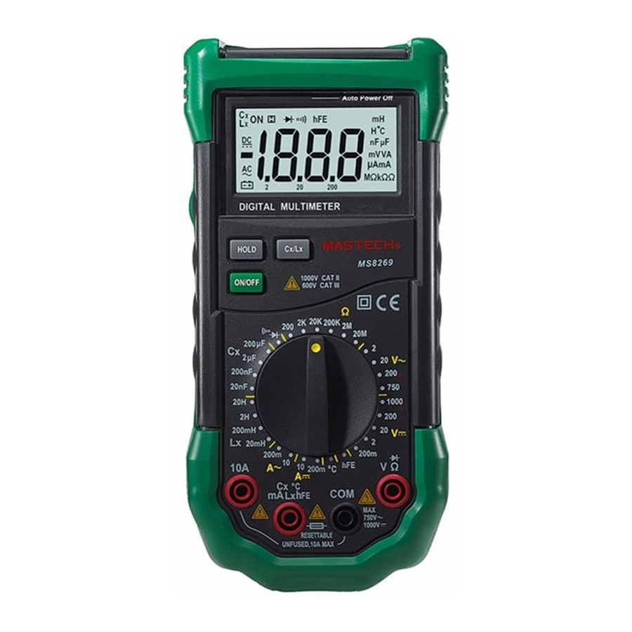
Page 5: Descriptions Of Meter Exterior
conducting ON/OFF tests, the meter can withstand AC voltages not exceeding 250V or equivalent effective voltages. * When measuring capacitance, inductance, temperature, or mA level of current, or conducting hFE tests on transistors, protect meter with self-recovery fuse (F500mA/250V). 2. Descriptions of meter exterior 2.1 Exterior of the meter 1. -
Page 6: Function Keys
The meter is under the mode of ON/OFF test. The meter is under the mode of capacitance, inductance measurement. Table 1 Displayed symbols (Continued) The meter is under the mode of data holding. Fig.1 Display ℃ degree Celcius. Unit ℃ ℃ ℃ ℃ Table 1 Displayed symbols temperature. -
Page 7: Input Sockets
Function Operation descriptions connected to the red measuring tip or “+” ON/OFF Turn the power of the meter on output plug of the dedicated multi-functional Switch at any or off position. test sockets). HOLD Press HOLD key to switch to or Switch at any Positive input terminal for 10A current (to be quit from the data holding... -
Page 8: Energy Saving Function Of The Battery
To set or cancel the mode of data holding: To measure AC or DC voltages: 1. Press “HOLD” key once, the current read value will 1. Switch the rotary switch to a proper position. ” be kept on display, and in the mean time the “ 2. -
Page 9: Diode Measurement
2. Connect the black measuring tip and the red In order to prevent the meter or the equipment to measuring tip to the input socket of COM and the be measured from being damaged, always input socket of VΩ, respectively. turn off all power supplies for the circuit to be 3. -
Page 10: Measuring Capacitance
capacitors before conducting the Humming tip to the COM input socket and the CX input socket. ON/OFF test. (You can also use the dedicated multi-functional test sockets to measure capacitance). 3. Measure the capacitance of the capacitor to be tested with the other ends of the test tips, and read the To conduct ON/OFF tests: 1. -
Page 11: Measuring Inductance
the hFE value of the transistor to be tested. Measuring temperatures: 1. Set the rotary switch at the position of ℃ , and LCD will 3.2.7 Measuring inductance output the value of the ambient temperature. 2. Properly connect the multi-function test sockets to the Do not conduct measurements for frequency meter (“+”... -
Page 12: Measuring Current
The ranges for DC current of this meter are 200.0mA and 4 Technical Parameters 10.00A; The ranges for AC current of this meter are 4.1 General parameters 200.0mA and 10.00A. Surrounding conditions for operation: Measuring current: 600V CAT. Ⅲ a n d 1000V CAT. -
Page 13: Precision Parameters
(effective value). displayed. Frequency response: 40Hz-400Hz (40-200Hz for the range Power: DC 9V of 750V), sine wave effective value (mean value Battery type: NEDA 1604, 6F22, or 006P. response) Dimensions: 195(L)×92(W)×55(H) mm. 4.2.3 Transistor Weight: about 380g (with batteries). Range Description Test condition The display outputs the... -
Page 14: Capacitance
200mA 0.1mA Description Test conditions ± ( 1 .5% of reading +1 graduation) Funct. 10mA The humming of the built-in ± ( 2 .0% of reading +5 graduation) Open-circuit voltage: Overload protection: self-recovery fuse (F500mA/250V); No buzzer means that about 500mV fuse protection for the range of 10A. -
Page 15: Routine Maintenance
service staff and you can get access to information that the test tips are disconnected from the regarding related calibration, performance tests, and circuit to be tested before taking off the battery services. cover for replacing the battery. 5.1 Routine maintenance In order to avoid electric shock or damaging the meter, please do not wet the interior of the meter. - Page 16 6. Put a new 9V (6F22) battery in place. 7. Put the battery cover in place, and tighten the screws.
Need help?
Do you have a question about the MS8269 and is the answer not in the manual?
Questions and answers