Table of Contents
Advertisement
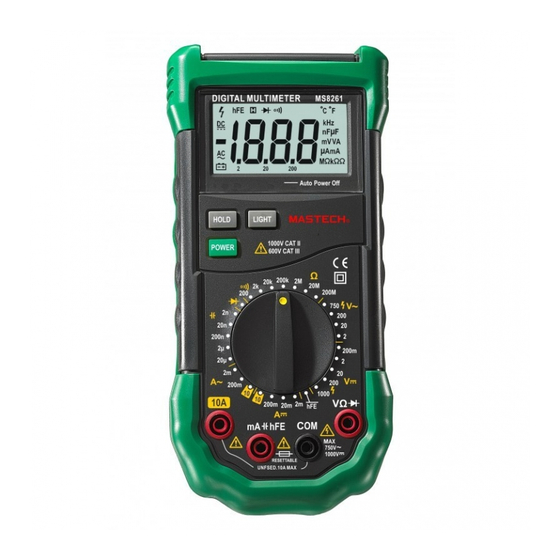
HANDHELD
DIGITAL MULTIMETER
OPERATOR'S
INSTRUCTION MANUAL
GENERAL INSTRUCTIONS
This instrument complies with IEC 1010-1 (61010-1@IEC: 2001), CAT. II 1000V and CAT. III 600V
overvoltage standards. See Specifications.
To get the best service from this instrument, read carefully this user's manual and respect the detailed
safety precautions.
International symbols used on the Meter and in this manual are explained in chapter 1.1.3
Precautions safety measures
1.1.1 Preliminary
* Measurement category III is for measurements performed in the building installation.
NOTE: Examples are measurements on distribution boards, circuit-breakers, wiring, including cables,
bus-bars, junction boxes, switches, socket-outlets in the fixed installation, and equipment for industrial
use and some other equipment, for example, stationary motors with permanent connection to the fixed
installation.
* Measurement category II is for measurements performed on circuits directly connected to the low
voltage installation.
NOTE: Examples are measurements on household appliances, portable tools and similar equipment.
* Measurement category I is for measurements performed on circuits not directly connected to MAINS.
NOTE: Examples are measurements on circuits not derived from MAINS, and specially protected
(internal) MAINS derived circuits. In the latter case, transient stresses
are variable; for that reason, requires that the transient withstand capability of the equipment is made
known to the user.
* When using this Multimeter, the user must observe all normal safety rules concerning:
― protection against the dangers of electric current.
― protection of the Multimeter against misuse.
* For your own safety, only use the test probes supplied with the instrument. Before use, check that they
are in good condition.
1.1.2 During use
* If the meter is used near noise generating equipment, be aware that display may become unstable or
indicate large errors.
* Do not use the meter or test leads if they look damaged.
* Use the meter only as specified in this manual; otherwise, the protection provided by the meter may be
impaired.
Advertisement
Table of Contents

Subscribe to Our Youtube Channel
Related Manuals for Mastech ms8261


Summary of Contents for Mastech ms8261
- Page 1 HANDHELD DIGITAL MULTIMETER OPERATOR’S INSTRUCTION MANUAL GENERAL INSTRUCTIONS This instrument complies with IEC 1010-1 (61010-1@IEC: 2001), CAT. II 1000V and CAT. III 600V overvoltage standards. See Specifications. To get the best service from this instrument, read carefully this user's manual and respect the detailed safety precautions.
- Page 2 * Use extreme caution when working around bare conductors or bus bars. * Do not operate the meter around explosive gas, vapor, or dust. * Verify a Meter's operation by measuring a known voltage. Do not use the Meter if it operates abnormally. Protection may be impaired.
- Page 3 1.1.4 Instructions * Remove test leads from the Meter before opening the Meter case or battery cover. * When servicing the Meter, use only specified replacement parts. * Before opening up the instrument, always disconnect from all sources of electric current and make sure you are not charged with static electricity, which may destroy internal components.
- Page 4 Figure 1.Display Table 1. Display Symbols Symbol Meaning The battery is low. Warning: To avoid false readings, which could lead possible electric shock or personal injury, replace the battery as soon as the battery indicator appears. Indicates negative readings. Indicator for ac voltage or current. voltage current displayed as the average of the...
- Page 5 Farad. The unit of capacitance. Microfarad.1x10-6 or 0.000001 (F, nF farads. Nanofarad. 1x10⁻⁹ 0.000000001 farads. 2.3 Keypad See Table 2 indicated for information about the keypad operations. Table 2. Keypad Function Operation performed ON/O switch turn the meter on or position HOLD switch...
- Page 6 ( User's manual One piece ( Test leads One piece ( Carry case One piece Special Multi-function One piece socket . FUNCTION DESCRIPTION 3.1 General Functions 3.1.1 DATA HOLD mode Data Hold mode makes the meter stop updating the display. Data Hold function can be cancelled by changing the measurement mode, or push HOLD key again.
- Page 7 COM terminal, and make sure the zero display. 3.2.2 Resistance measurement To avoid electrical shock and/or damage to the instrument, disconnect circuit power and discharge all high-voltage capacitors before measuring resistance. Resistance is an opposition to current flow. The unit of resistance is the ohm ((). The Meter's resistance ranges are 200.0(, 2.000k(, 20.00k(, 200.0k(, 2.000M(, 20.00M( and 200.0M(.
- Page 8 2. Connect the black and red test leads to the COM and terminals respectively. 3. For forward-bias readings on any semiconductor component, place the red test lead on the component's anode and place the black test lead on the component's cathode. 4.
- Page 9 Some tips for measuring capacitance: ( The meter may take a few seconds to stabilize reading. This is normal for high capacitance measuring. ( To improve the accuracy of measurements less than 20nF, subtract the residual capacitance of the Meter and leads. 3.2.6 Transistor measurement To avoid electrical shock and/or damage to the instrument, do not apply more than...
- Page 10 5. Turn on the power of the measured circuit, and then read the display. Be sure to note the measurement units at the right side of the display (mA or A). When only the figure "1" displayed, it indicates overrange situation and the higher range has to be selected. 6.
- Page 11 Input impedance: 10M(Max. input voltage: 250Vdc or ac rms for 200mV range and 1000Vdc or 750V ac rms for other ranges, 4.2.2 AC Voltage Range Resoluti Accuracy 10mV ±(0.8% of rdg +3 digits) 200V 100mV 750V ±(1.2% of rdg +3 digits) Input impedance: 10M( Max.
- Page 12 4.2.6 Transistor Description Test Condition Display read Base Current approx. HFE value approx. 10μA, (0-1000) Vce approx. 2.8V. transistor under test (all type). 4.2.7 Capacitance Range Resolutio Accuracy 20nF 10pF 200nF 0.1nF ±(4.0% of rdg+3 digits) 20(F 10nF Overload protection: Resettable fuse (F200mA/250V). 4.2.8 DC Current Resolutio Range...
- Page 13 5. MAINTENANCE Do not attempt to repair or service your Meter unless you are qualified to do so and have the relevant calibration, performance test, and service information. 5.1 General Maintenance To avoid electrical shock or damage to the meter, do not get water inside the case. Remove the test leads and any input signals before opening the case Periodically wipe the case with a damp cloth and mild detergent.
- Page 14 Battery cover Battery cover Battery cover Battery cover 9V Battery 9V Battery 9V Battery 9V Battery Figure 2. Battery and Fuse Replacement CAUTION Using this appliance in an environment with a strong radiated radio-frequency electromagnetic field (approx. 3V/m), may influence its measuring accuracy. The measuring result can be strongly deviating from the actual value.
Need help?
Do you have a question about the ms8261 and is the answer not in the manual?
Questions and answers