Table of Contents
Advertisement
Quick Links
Advertisement
Table of Contents

Related Manuals for Mastech MS8268


Summary of Contents for Mastech MS8268
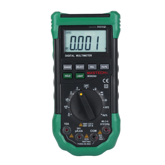
- Page 1 MS8268 HANDHELD DIGITAL MULTIMETER OPERATOR’S INSTRUCTION MANUAL...
-
Page 2: Table Of Contents
Table of Contents Table of Contents TITLE PAGE TITLE PAGE 1. GENERAL INSTRUCTIONS 3.2.2 Resistance measurement 1.1 Precaution safety measures 3.2.3 Diode Test 1.1.1 Preliminary 3.2.4 Continuity Check 1.1.2 During use 3.2.5 Transistor measurement 1.1.3 Symbols 3.2.6 Capacitance measurement 1.1.4 Instructions 3.2.7 Frequency and Duty Cycle measurement 1.2 Safety mechanisms 3.2.8 Current measurement... -
Page 3: General Instructions
1. GENERAL INSTRUCTIONS * When using this Multimeter, the user must observe all This instrument complies with IEC 1010-1 (61010-1@IEC: normal safety rules concerning: 2001), CAT. II 1000V and CAT. III 600V overvoltage ― Protection against the dangers of electric current. standards. -
Page 4: Symbols
* Do not apply any voltage measurement between the 10A * Replace the batteries as soon as the battery indicator terminal and the COM terminal. ) appears. With a low battery, the Meter might * Caution when working with voltages above 60Vdc or 30Vac produce false readings that can lead to electric shock and rms. -
Page 5: Safety Mechanisms
2. DESCRIPTION * Any adjustment, maintenance or repair work carried out on 2.1 Instrument Familiarization the meter while it is live should be carried out only by appropriately qualified personnel, after having taken into account the instructions in this present manual. * A "qualified person"... -
Page 6: Lcd Display
Table 1. Display Symbols (continued) 2.2 LCD Display Symbol Meaning See Table 1 indicated for information about the LCD display. RELΔ Indicator for the Relative measurement. Indicator for the Diode Test mode Indicator for the transistor test mode Indicator for the Continuity Check mode. Indicator for the Data Hold mode Volts. -
Page 7: Keypad
2.3 Keypad Table 2. Keypad(continued) See Table 2 indicated for information about the keypad Function Operation performed operations. Table 2. Keypad HOLD Any switch Press HOLD to enter and exit position the Data Hold mode. Function Operation performed 1. Press RANGE to enter the RANGE V~,V ,Ω,... -
Page 8: Rotary Switch
2.5 Rotary switch 3. FUNCTION DESCRIPTION A eleven-position rotary selector switch gives access to 3.1 General Functions the following quantities: 3.1.1 Misconnection alarm system ¥ Current: 10A The input terminals of the meter are equipped with sound ¥ Current: mA and light alarms against misconnection of test leads. -
Page 9: Data Hold Mode
3.1.2 DATA HOLD mode NOTE: If you manually change the measurement range after entering the Data Hold modes, the Meter exits this Data Hold mode makes the meter stop updating the mode. display. Enabling Data Hold function in autorange mode 2.
Need help?
Do you have a question about the MS8268 and is the answer not in the manual?
Questions and answers