
Related Manuals for Mastech MS8251B


Summary of Contents for Mastech MS8251B
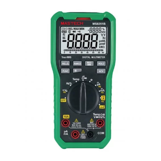
- Page 1 MS8251B DIGITAL MULTIMETER OPERATION MANUAL MS8251B REL MAX MIN AUTO 60 66...
-
Page 2: Safety Information
1. Safety Information 1.2 Use 1.2.1 Turn the rotary switch to the required function and range to be measured. Warning 1.2.2 When using the CAT Ⅳ environment, if the To reduce the risk of electrical shock, product damage measuring voltage between terminals and earth or personal injury, please follow the safety instructions ground exceeds 600V, CAT III environments or described in the user manual. - Page 3 Features and Components CAT III Refers to the impulse withstand voltage protection The MS8251B is a portable, hand-held yet professional level in accordance with IEC-61010-1 standard meter that features an LCD with backlight, overload overvoltage (installation)category III,pollution protection and low battery indicator.
- Page 4 2.2 Buttons and Symbols HOLDbutton: hold current reading on screen. FUNC button: switch between functions. RANGE button: switch between auto/manual ranges. REL button: relative reading MS8251B MAX/MIN button: switch between maximum/ minimum REL MAX MIN readings. AUTO utton: turn on/off backlight.
-
Page 5: Specifications
3. Specifications Alternating current The Meter should be calibrated annually between Direct current 18°C~28°C and a relative humidity less than 75%. Diode 3.1 General Specifications Continuity 3.1.1 Manual and auto range Autoranging mode AUTO 3.1.2 Full range overload protection Maximum value 3.1.3The maximum voltage allowed between the measuring Minimum value end and the earth:CAT IV measurement environment... - Page 6 3.2.3 DC Voltage 3.2 Technical Specifications range 3.2.1 True RMS Characteristics Resolution Accuracy ±(0.8% of reading + 3 digits) • For non-sinusoidal signal measurement, the Meter 660mV 0.1mV provides more accurate measurement than the 6.6V 0.001V traditional averaging method. 0.01V •...
- Page 7 3.2.4.2 AC Voltage Low Impedance(lo-Z) 3.2.6 Capacitance range Frequency Range range Resolution Accuracy Resolution Accuracy ±(1.5% reading ±(4.0% reading + 5 digits) 6.6nF 0.001nF 660mV 0.1mV 40 ~ 60Hz + 5 digits) 66nF 0.01nF ±(1.2% reading 660nF 0.1nF 6.6V 0.001V 40 ~400Hz + 5 digits) 6.6µF...
- Page 8 3.2.9 Frequency 3.2.10 DC Current 3.2.9.1 Frequency (V position): range Resolution Accuracy range Resolution Accuracy 660 A µ 0.1µA 66Hz 0.01Hz 6600 A µ 1µA ±(1.0% reading + 5 digits) 660Hz 0.1Hz 10µA 66mA ±(1.5% reading + 5 digits) 6.6kHz 0.001kHz 100µA 660mA...
- Page 9 4.3.2 Press “REL ” again to return to normal. 3.2.12 Temperature 4.4 Maximum/Minimum Reading Range Input Test Range Accuracy 4.4.1 Press “MAX/MIN” to display the maximum value Ambient Temp ±2 digits recorded ±4 digits 0~1000°C 400°C 4.4.2 Press “MAX/MIN” again to display the minimum value recorded.
- Page 10 Note: 4.11 Continuity 1.Even though there is no indication,voltage may still 4.11.1 In resistance mode, press “FUNC” to switch to exist.Do not rely solely on NCV detector to determine continuity mode. the presence of voltage in a wire.The measurement 4.11.2 Connect the red test lead to the input jack and the may be affected by the design of the outlet,type of black test lead to the “COM”...
-
Page 11: Maintenance
4.15 Current 4.15.1 Remove power to the circuit and discharge all capacitance. 4.15.2 Move the rotary switch to the appropriate position (µA, mA or A). 4.15.3 Connect the black test lead to the “COM” jack. If the current to be measured is <600mA, connect the red test lead to the “µAmA”... - Page 12 00-05-3591...
Need help?
Do you have a question about the MS8251B and is the answer not in the manual?
Questions and answers