Table of Contents
Advertisement
GENERAL INSTRUCTIONS
This instrument complies with IEC 1010-1 (61010-1@IEC: 2001), CAT. II 1000V and CAT. III 600V
overvoltage standards. See Specifications.
To get the best service from this instrument, read carefully this user's manual and respect the detailed
safety precautions.
International symbols used on the Meter and in this manual are explained in chapter 1.1.3
Precautions safety measures
1.1.1 Preliminary
* Measurement category III is for measurements performed in the building installation.
NOTE: Examples are measurements on distribution boards, circuit-breakers, wiring, including cables,
bus-bars, junction boxes, switches, socket-outlets in the fixed installation, and equipment for industrial
use and some other equipment, for example, stationary motors with permanent connection to the fixed
installation.
* Measurement category II is for measurements performed on circuits directly connected to the low
voltage installation.
NOTE: Examples are measurements on household appliances, portable tools and similar equipment.
* Measurement category I is for measurements performed on circuits not directly connected to MAINS.
NOTE: Examples are measurements on circuits not derived from MAINS, and specially protected
(internal) MAINS derived circuits. In the latter case, transient stresses
are variable; for that reason, requires that the transient withstand capability of the equipment is made
known to the user.
* When using this Multimeter, the user must observe all normal safety rules concerning:
― protection against the dangers of electric current.
― protection of the Multimeter against misuse.
* For your own safety, only use the test probes supplied with the instrument. Before use, check that they
are in good condition.
1.1.2 During use
* If the meter is used near noise generating equipment, be aware that display may become unstable or
indicate large errors.
* Do not use the meter or test leads if they look damaged.
* Use the meter only as specified in this manual; otherwise, the protection provided by the meter may be
impaired.
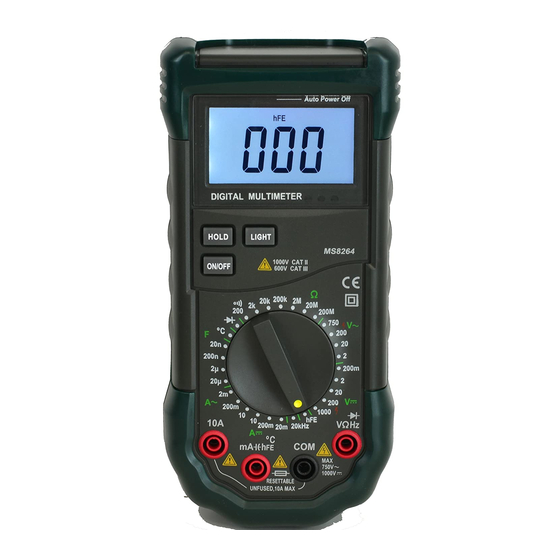
HANDHELD
DIGITAL MULTIMETER
OPERATOR'S
INSTRUCTION MANUAL
Advertisement
Table of Contents

Related Manuals for Mastech MS8264


Summary of Contents for Mastech MS8264
- Page 1 HANDHELD DIGITAL MULTIMETER OPERATOR’S INSTRUCTION MANUAL GENERAL INSTRUCTIONS This instrument complies with IEC 1010-1 (61010-1@IEC: 2001), CAT. II 1000V and CAT. III 600V overvoltage standards. See Specifications. To get the best service from this instrument, read carefully this user's manual and respect the detailed safety precautions.
- Page 2 * Use extreme caution when working around bare conductors or bus bars. * Do not operate the meter around explosive gas, vapor, or dust. * Verify a Meter's operation by measuring a known voltage. Do not use the Meter if it operates abnormally. Protection may be impaired.
- Page 3 1.1.4 Instructions * Remove test leads from the Meter before opening the Meter case or battery cover. * When servicing the Meter, use only specified replacement parts. * Before opening up the instrument, always disconnect from all sources of electric current and make sure you are not charged with static electricity, which may destroy internal components.
- Page 4 See Table 1 indicated for information about the LCD display. Figure 1.Display Table 1. Display Symbols Symbol Meaning The battery is low. Warning: To avoid false readings, which could lead possible electric shock or personal injury, replace the battery as soon as the battery indicator appears.
- Page 5 Ohm. The unit of resistance. Kilohm. 1x10³ or 1000 ohms. (, k(, M( Megohm. 1x10⁶ or 1,000,000 ohms. Kilohertz. 1x10³ or 1000 hertz. Farad. The unit of capacitance. Microfarad.1x10-6 or 0.000001 (F, nF farads. Nanofarad. 1x10⁻⁹ 0.000000001 farads. 2.3 Keypad See Table 2 indicated for information about the keypad operations.
- Page 6 multi-function socket) Input 200mA to 10A current measurements. (Receiving the red test lead) 2.5 Accessories Delivered with the multimeter: ( User's manual One piece ( Test leads One piece ( Carry case One piece "K" type bead One piece Thermocouple Special Multi-function One piece...
- Page 7 3. Connect the test leads to the circuit being measured 4. Read the displayed value. The polarity of red test lead connection will be indicated when making a DCV measurement. NOTE: ( Unstable display may occur especially at DC200mV and AC2V ranges, even though you do not put test leads into input terminals, in this case, if an erroneous reading is suspected, short the V terminal and the COM terminal, and make sure the zero display.
- Page 8 Use the diode test to check diodes, and other semi- conductor devices. The diode test sends a current through the semiconductor junction, and then measures the voltage drop across the junction; a good silicon junction drops between 0.5V and 0.8V. To test a diode out of a circuit: 1.
- Page 9 To measure capacitance: 1. Set the rotary switch to proper range. 2. Connect the black and red test leads to the COM and terminals respectively (or you can measure the capacitance by using the special Multi-Function Socket). 3. Connect the test leads to the capacitor being measured and read the displayed value. Some tips for measuring capacitance: ( The meter may take a few seconds to stabilize reading.
- Page 10 To avoid electrical shock and/or damage to the instrument, do not apply more than 250Vdc or 250Vac rms between the ℃ terminal and the COM terminal. To avoid electrical shock, do not use this instrument when voltages measurement surface exceed 60v dc or 24v rms.
- Page 11 Connect the black test lead to the more negative side of the break; connect the red test lead to the more positive side of the break. (Reversing the leads will give a negative reading, but will not damage the Meter.) 5.
- Page 12 10mV 200V 100mV 1000 ±(0.8% of rdg +2 digits) Input impedance: 10M( Max. input voltage: 250Vdc or ac rms for 200mV range and 1000Vdc or 750V ac rms for other ranges, 4.2.2 AC Voltage Range Resoluti Accuracy 10mV ±(0.8% of rdg +3 digits) 200V 100mV 750V...
- Page 13 forward voltage of diode Forward DC Current: approx. 1mA Reversed DC Voltage: approx. 2.8V Overload protection: 380Vdc or 380Vac rms. 4.2.6 Audible continuity Rang Continuity beeper ≤30( Open circuit voltage: Less than 700mV. Overload protection: 380Vdc or 380Vac rms. 4.2.7 Transistor Description Test Condition Display...
- Page 14 4.2.10 DC Current Resolutio Range Accuracy 20mA 10(A ±(1.5% of rdg+1 digit) 200mA 0.1mA 10mA ±(2.0% of rdg+5 digits) Overload protection: Resettable fuse (F200mA/250V). 10A range unfused Max. input current: 200mA dc or 200mA ac rms for mA range, 10A dc or 10A ac rms for 10A ranges. For measurements>5A, 4 minutes maximum ON to measure 10 minutes OFF;...
- Page 15 replace the battery as soon as the battery indicator ( ) appears. Before replacing the battery, disconnect test leads and/or any connectors from any circuit under test, turn the meter off and remove test leads from the input terminals. To replace the battery (see Figure 2.): ( Turn the meter off.
Need help?
Do you have a question about the MS8264 and is the answer not in the manual?
Questions and answers