Table of Contents
Advertisement
Quick Links
Advertisement
Table of Contents

Related Manuals for Commell LN-D70


Summary of Contents for Commell LN-D70
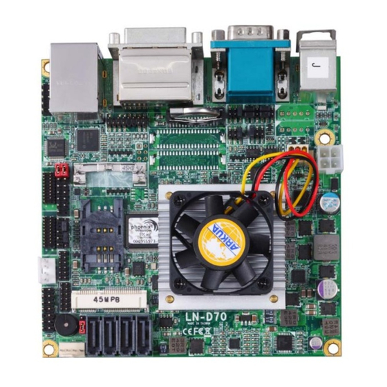
- Page 1 LN-D70 Nano-ITX Motherboard User’s Manual Edition 1.14 2015/04/02...
-
Page 2: Packing List
Any questions please visit our website at h ttp://www.commell.com.tw Packing List: Please check the package content before you starting using the board. Hardware: LN-D70 Mini-ITX Motherborad x 1 Cable Kit: SATA Cable x 2 OALSATA3-L / (1040529) Dual COM PORT Cable x 1 OALES-BKU2NB / (1040090) USB2.0 Cable x 1... - Page 3 LN-D70 User’s Manual SATA Power Cable x 1 1 to 3 power output cable x 1 (OAL4P-S2)/ (1040054) (OAL4P-2)/ (1040051) DC Power Cable x 1 (OALDC-A)/ (1040433) Audio Cable x 1 (OALPJ-HD-NB)/ (1040121) Printed Matters: Driver CD (Including User’s Manual) x 1...
- Page 4 LN-D70 User’s Manual Index Chapter 1 <Introduction> ................5 1.1 <Product Overview>..................5 1.2 <Product Specification>................6 1.3 <Mechanical Drawing>................. 8 1.4 <Block Diagram>..................9 Chapter 2 <Hardware Setup>................9 2.1 <Connector Location> .................. 9 2.2 <Jumper Location & Reference>..............10 2.3 <Connector Reference> ................11 2.3.1 <Internal Connectors>...
- Page 5 Contact Information..................43 Chapter 1 <Introduction> 1.1 <Product Overview> LN-D70 is the system-on-chip (SoC) designed for intelligent systems, delivering outstanding compute, graphical, and media performance while operating in an extended range of thermal conditions. These SoCs are based on the Silvermont microarchitecture, utilizing Intel’s industry-leading 22nm process technology with 3-D Tri-Gate transistors,...
-
Page 6: Product Specification
LN-D70 User’s Manual processing, audio with digital signal processing, multiple storage types, and legacy embedded I/O. Provides interface expansion capabilities through industry-standard high-bandwidth interfaces such as PCI Express* Gen 2.0, Hi-speed USB 2.0, and USB 3.0 connectivity. All in One multimedia solution Based on Intel®... - Page 7 LN-D70 User’s Manual 4 x RS232, 1 x GPIO, 1 x Audio connector, 1 x SMBUS connector, 1 x CRT, 2 Internal I/O Port x LVDS, 1 x LPC, 2 x USB 2.0 and 2 x SATAII, 2 x SATAIII.
-
Page 8: Mechanical Drawing
LN-D70 User’s Manual 1.3 <Mechanical Drawing>... -
Page 9: Block Diagram
LN-D70 User’s Manual 1.4 <Block Diagram> Chapter 2 <Hardware Setup> 2.1 <Connector Location>... -
Page 10: Jumper Location & Reference
LN-D70 User’s Manual 2.2 <Jumper Location & Reference> Jumper Function JRTC CMOS Operating/Clear Setting JVLCD Panel1、2 Voltage Setting Power mode select Com1 Voltage Setting (For Pin 9) Com2 Voltage Setting (For Pin 9) JCSEL1 COM2 RS-232 RS422 RS485 Setting JCSEL2... -
Page 11: Connector Reference
LN-D70 User’s Manual 2.3 <Connector Reference> 2.3.1 <Internal Connectors> Connector Function Remark FCBGA1170 CPU SO-DIMM 1/2 204 -pin DDR3L SO-DIMM socket SATAII 1/2 7-pin Serial ATAII connector SATAIII 1/2 7-pin Serial ATAIII connector DC_IN DC 6~27V input connector DC_OUT 4-pin DC output connector... -
Page 12: Memory Setup
Serial port connector PS/2 PS/2 keyboard and mouse connector 2.4 < Memory Setup > LN-D70 has two 204-pin DDR3L DIMM support up to 8GB of memory capacity and 1.35 Voltage. The memory frequency supports 1066/1333 MHz. Only Non-ECC memory is supported. -
Page 13: Cmos & Atx Setup
LN-D70 User’s Manual 2.5 <CMOS & ATX Setup> The board’s data of CMOS can be setting in BIOS. If the board refuses to boot due to inappropriate CMOS settings, here is how to proceed to clear (reset) the CMOS to its default values. -
Page 14: Ethernet Interface
LN-D70 User’s Manual 2.6 <Ethernet Interface> The board integrates with Intel I210 Gigabit Ethernet, as the PCI Express bus. The Intel I210 supports triple speed of 10/100/1000Base-T, with IEEE802.3 compliance and Wake-On-LAN supported. 2.7 <Onboard Display Interface> Based on Intel processor with built-in HD Graphic, the board provides one DVI connector &... -
Page 15: Lvds
LN-D70 User’s Manual 2.7.2 <LVDS> The board provides two 40-pin LVDS connector for 18/24-bit single/dual channel panels, supports up to 1920 x 1080 resolution, with one LCD backlight inverter Please install LVDS cable before connector and two jumper for panel voltage setting. - Page 16 LN-D70 User’s Manual Connector: CN_INV1 and CN_INV2 Type: 5-pin LVDS Power Header Description +12V Reserved (Note) ENABKL Note1 1. LVDS1 (CN_INV1) and LVDS2 (CN_INV2) can be connected and enabled simultaneously but the PWM feature will not function if both LVDS1 and LVDS2 are enabled at the same time.
- Page 17 LCD Installation Guide: Preparing the LN-D70, LCD panel and the backlight inverter. Please check the datasheet of the panel to see the voltage of the panel, and set the jumper JVLCD to +12V or +5V or +3.3V.
-
Page 18: Vga Interface
LN-D70 User’s Manual BIOS panel type selection form (BIOS Version:1.0) Single / Dual channel Single / Dual channel Output format Output format 640 x 480 1680 x 1050 800 x 600 1920 x 1200 1024 x 768 1440 x 900... -
Page 19: Integrated Audio Interface
LN-D70 User’s Manual Signal Signal -CRTATCH IOGND1 IOGND1 IOGND1 -CRTATCH 5VCDA 5HSYNC 5VSYNC 5VCLK 2.8 <Integrated Audio Interface> The board integrates onboard audio interface with REALTEK ALC262 code, with Intel next generation of audio standard as High Definition Audio, it offers more vivid sound and other advantages than former HD audio compliance. - Page 20 LN-D70 User’s Manual 2 DAC channels support 16/20/24-bit PCM format for 2 audio solution Compatible with HD Meets Microsoft WHQL/WLP 2.0 audio requirements Connector: CN_AUDIO Type: 10-pin (2 x 5) header (pitch = 2.54mm) Description Description MIC_L Ground MIC_R Speaker_R...
-
Page 21: Usb Interface
LN-D70 User’s Manual 2.9 <USB Interface> LN-D70 integrates 1 x USB3.0 / 2.0 and 3 x USB2.0 , The specifications of USB3.0 are listed below: Interface USB3.0 Transfer Rate Up to 5Gb/s Voltage The USB3.0 port need to Install USB 3.0 eXtensible Host Controller Driver enable xHCI Mode. - Page 22 LN-D70 User’s Manual Step3. enable “xHCI Mode” and push “F10” to save configuration. Restart your computer. Step4. If you enable xHCI Mode , USB 2.0 and USB 3.0 ports can’t use without drive. We recommend that you connect PS/2 mouse / keyboard installing USB 3.0 driver.
- Page 23 LN-D70 User’s Manual Step6. Lastly, the “Setup Complete” screen appears so click “Finish” to restart your computer. The specifications of USB2.0 are list: Interface USB2.0 Transfer Rate Up to 480Mb/s Voltage...
- Page 24 LN-D70 User’s Manual Connector: CN_USB Type: 10-pin (2 x 5) header (pitch = 2.54mm) Description Description (5V_SB/ 5V) (5V_SB/ 5V) Data0- Data1- Data0+ Data1+ Ground Ground Ground enable xHCI Mode. CN_USB need to Connector: JVUSB Type: 6-pin Power select jumper Description 1-3 &...
-
Page 25: Serial Port
LN-D70 User’s Manual Warning: others cause damages 2.10 <Serial Port> The board supports four RS232 serial port and one jumper selectable RS232/422/485 serial ports. The jumper JCSEL1 & JCSEL2 can let you configure the communicating modes for COM2. Connector: COM1... - Page 26 LN-D70 User’s Manual Type: 20-pin (2 x 10) header pitch = 2.54x1.27mm Description Description DCD1 RXD1 TXD1 DTR1 GND1 DSR1 RTS1 CTS1 DCD2 DTR2 Ground DSR2 RTS2 CTS2...
-
Page 27: Pcie Mini Card And Sim Interface
LN-D70 User’s Manual Function JCSEL1 JCSEL2 RS-422 RS-485 RS-232 (Default) Default setting: JCSEL1: (1-3, 2-4, 7-9, 8-10) JCSEL2: (1-2) Jumper: JP1/JP2 (COM1/2) Type: onboard 6-pin header Power Mode JP1/2 Pin 9 with 5V Power Pin 9 with 12V Power Standard COM port Default setting 2.11 <PCIE Mini Card and SIM Interface>... - Page 28 LN-D70 User’s Manual SIMVPP SIMDATA Jumper: JMSATA Type: onboard 3-pin header MINI_CARD Mode JMSATA Supply mSATA 1-2(Note) MINI_CARD Default setting: 2-3 Note:SATA2-2 and mSATA can’t be enabled simultaneously 2.11.1 <SIM Setup> Step1. SIM card holder is marked by circle. Slide the cap toward OPEN direction.
- Page 29 LN-D70 User’s Manual Step 2. Make sure that the cap is now at the OPEN position. Step 3. Flip the cap up for inserting a SIM card into. Step 4. Insert a SIM card as shown in the photo. Be sure that the corner cut is on top and the golden pads are up.
-
Page 30: Gpio And Smbus Interface
LN-D70 User’s Manual Step 6. Press down and slide the cap to the CLOSE position. Be sure that the cap is tightly held with the socket. 2.12 <GPIO and SMBUS Interface> The board provides a programmable 8-bit digital I/O interface; you can use this general purpose I/O port for system control like POS or KIOSK. -
Page 31: Power Supply And Fan Interface
LN-D70 User’s Manual Connector: CN_SMBUS Type: 5-pin header for SMBUS Ports Description SMBDATA SMBCLK Ground 2.13 <Power Supply and Fan Interface > 2.13.1 <Power Input> The board requires onboard 4-pin DC-input connector voltage range is from 6V to 24V, , for the input current, please take a reference of the power consumption report on appendix. -
Page 32: Power Output
LN-D70 User’s Manual Connector: DC_IN Type: 4-pin standard Pentium 4 additional +12V power connector Description Description Ground Ground +6V~+24V +6V~+24V 2.13.2 < Power Output > Connector: DC_OUT Type: 4-pin connector for +5V/+12V output Description Description Description Description +12V Ground Ground Note: Maximum output current 12V/3A, 5V/3A 2.13.3 <Fan connector>... -
Page 33: Switch And Indicator
LN-D70 User’s Manual Connector: CPUFAN Type: 4-pin fan wafer connector Description Description Ground +12V Fan Speed Detection Fan Control Connector: SYSFAN Type: 4-pin fan wafer connector Description Description Ground +12V Fan Speed Detection Fan Control 2.14 <Switch and Indicator> The JFRNT provides front control panel of the board, such as power button, reset and beeper, etc. - Page 34 LN-D70 User’s Manual HDLED+ PWRLED+ IDE LED Power HDLED- Reset+ PWRLED- Reset Reset- SPK+ Speaker Power PWRBT+ Button PWRBT- SPK-...
-
Page 35: Chapter 3
LN-D70 User’s Manual Chapter 3 <System Setup> 3.1 <Audio Configuration> The board integrates REALTEK® ALC262 code. It can support 2-channel sound under system configuration. Please follow the steps below to setup your sound system. Install REALTEK HD Audio driver. Lunch the control panel and Sound Effect Manager. - Page 36 LN-D70 User’s Manual 1. Click right button on the desktop to lunch Screen resolution > Advanced settings … button for more specificity setup. Graphics Properties 2. Click Click Graphics Properties... for advanced setup 3. This setup options can let you define each device settings.
-
Page 37: Sata Configuration
LN-D70 User’s Manual 3.3 <SATA configuration> SATA Mode: This option can let you select whether the Serial ATA hard drives would work under normal IDE or AHCI. -
Page 38: Chapter 4
LN-D70 User’s Manual Chapter 4 <BIOS Setup> The motherboard uses the Phoenix BIOS for the system configuration. The Phoenix BIOS in the single board computer is a customized version of the industrial standard BIOS for IBM PC AT-compatible computers. It supports Intel x86 and compatible CPU architecture based processors and computers. -
Page 39: Appendix A
LN-D70 User’s Manual Appendix A <I/O Port Pin Assignment> A.1 <Serial ATA Port> Connector: SATA1/2 Type: 7-pin wafer connector GND RSATA_TXP1 RSATA_TXN1 GND RSATA_RXN1 RSATA_RXP1 GND A.2 <LAN Port> Connector: RJ45 Type: RJ45 connector with LED on bracket Description MI0+... -
Page 40: Appendix B
LN-D70 User’s Manual Appendix B <Flash BIOS> B.1 <Flash Tool> The board is based on Phoenix BIOS and can be updated easily by the BIOS auto flash tool. You can download the tool online from below link http://www.commell.com/Support/Product%20Technical%20Support/LN-D70. B.2 <Flash BIOS Procedure>... -
Page 41: Appendix C
LN-D70 User’s Manual 4. Type the ” fpt64.efi -y -f xxx.bin” command to start flash BIOS processes. ( xxx.bin means the BIOS file that you want to update) 5. When it finished all update processes, restart the system. Any question about the BIOS re-flash please contact your distributors or visit the web-site at below: http://www.commell.com.tw/support/support.htm... -
Page 42: Appendix D
LN-D70 User’s Manual -o 4E F1 -o 4F xx ;if set GPIO’s as output,in this register its value can be set Optional : -o 4E F2 -o 4F xx ; Data inversion register ; ‘1’ inverts the current valus of the bits ,’0’ leaves them as they are... -
Page 43: Contact Information
19F., No.94, Sec. 1, Xintai 5th Rd., Xizhi Dist., New Taipei Address City 22102, Taiwan +886-2-26963909 +886-2-26963911 Website h ttp://www.commell.com.tw i nfo@commell.com.tw (General Information) E-Mail t ech@commell.com.tw (Technical Support) Facebook https://www.facebook.com/pages/Taiwan-Commate-Computer-Inc/547993955271899 Twitter https://twitter.com/Taiwan_Commate Commell is a brand name of Taiwan commate computer Inc.
Need help?
Do you have a question about the LN-D70 and is the answer not in the manual?
Questions and answers