
Related Manuals for Grundig GRX-K4416A


Summary of Contents for Grundig GRX-K4416A
- Page 1 Owner's Manual Digital Recording Systems GRX‐K4416A 16 Channel H.264 Hybrid‐Recorder GRX‐K4416A © ASP AG ...
-
Page 2: Table Of Contents
Content 1. Introduction................................ 6 1.1 Available Versions............................... 7 1.2. Key Features of your DVR ............................ 7 2. Important Safety Instructions.......................... 8 3. Package Contents .............................. 9 4. Installation ................................ 10 4.1. Part Names and Functions .......................... 10 4.2. Remote Control: .............................. 12 4.2.1 Setting the remote control.......................... 13 4.3. Installation and Connection.......................... 14 4.3.1. Different configurations .......................... 22 4.4. Running the OSD menu ............................. 24 4.4.1. OSD Menu Configuration.......................... 24 4.4.2. Basic Settings ... - Page 3 6.8. Pause Live Screen .............................. 30 6.9. PTZ Control ................................ 32 6.9.1. Pan/Tilt ............................... 32 6.9.2. Zoom/Focus .............................. 32 6.9.3. Loading Preset ............................ 32 6.9.4. Save Preset .............................. 33 6.9.5. Auxiliary On .............................. 33 6.9.6. Auxiliary Off .............................. 33 6.10 Camera Setup .............................. 33 6.11. Implemented PTZ camera protocols: ...................... 34 7. Playback/Search .............................. 35 7.1. Playback/Search Mode ............................ 35 7.1.1. Playback on Standard monitor (16 / 9 / 4 division) .................. 35 7.1.2. Playback function............................ 35 7.1.3. Screen composition/names of the functions: .................... 36 7.2. Copy ................................... 37 7.2.1. EXE ................................ 39 8. Configuration................................ 41 ...
- Page 4 8.4.1. Event Check .............................. 59 8.4.2. Event Actions .............................. 60 8.4.3. Motion Detection ............................ 62 8.4.4. Sensor ................................. 63 8.5. Recording Setup .............................. 64 8.5.1. Continuous / Manual / Schedule Recording Setup .................. 64 8.5.2. Program Setup ............................ 66 9. GRUNDIG Web Viewer ............................ 67 9.1. System Requirements............................ 67 9.2. Login .................................. 67 9.3. User Setup ................................. 68 9.4. Available Browser .............................. 69 9.5. Monitor................................ 69 9.5.1. Screen division and changing video position .................... 70 9.5.2. Playback on Standard monitor (16 / 9 / 4 division) .................. 72 ...
- Page 5 9.6. Playback................................ 75 9.6.1. Video Division & Changing Channel...................... 75 9.6.2. Image recording............................ 75 9.6.3. Printing ............................... 76 9.6.4. Backup ................................ 76 9.6.5. Web Monitor .............................. 76 9.6.6. Channel On/Off............................ 77 9.6.7. Saving Time & Checking Rec. Capacity...................... 77 9.6.8. Searching in the Calendar ........................... 77 9.6.9. Functions at the bottom of the monitor ...................... 77 9.7. Java based Web Viewer ........................... 78 10. GRUNDIG Live Mobile Viewer .......................... 78 10.1. Log‐In Page .............................. 78 10.2. Monitoring Page .............................. 80 EC Declaration of Conformity ............................ 81 Open Source License Report of the Product ....................... 82 English ...
-
Page 6: Introduction
1. Introduction Thank you for purchasing a GRUNDIG digital video recorder for CVBS signals. This manual is for the recorder model GRX‐K4416A. Based on the Television Standard for FullHD Television, HD‐SDI products feature up to 2 Megapixel (1920x1080) pictures in real‐time (25/30fps) transmitted over coax cabling. Get the advantages of IP technology without their drawbacks: 16:9 megapixel pictures without network configuration, bandwidth problems and network security risks. Use the existing coax cables and only exchange the cameras and recorders. Get a “real” live picture and see the things that happen in the now, not a few seconds ago. Connect a monitor directly to a camera using only a HD‐SDI‐to‐HDMI converter. HD‐SDI is easy to handle, easy to install and produces amazing high quality pictures. Furthermore, the GRX‐K4416A is able to automatically detect and record analogue signals based on 760H or 960H standard. This allows the device to operate as a hybrid DVR. Before product installation and operation, please become thoroughly familiar with this user manual and other manuals referenced by this manual. This user manual, the software and the hardware described here are protected by copyright law. With the exception of copying for general use within fair use, copying and reprinting the user manual, either partially or in entirety, or translating it into another language without the consent of ASP AG is strictly prohibited. This specification may change without prior notice for improvement of product performance. Product Warranty and Limits of Responsibility: The manufacturer does not assume any responsibility concerning the sale of this product and does not delegate any right to any third party to take any responsibility on its behalf. No warranty is offered for any attachments or parts not supplied by the manufacturer. The product warranty does not cover cases of accidents, negligence, alteration, misuse or abuse, for example: ‐ Malfunctions due to negligence by the user ‐ Deliberate disassembly and replacement by the user ‐ Connection of a power source other than a properly rated power source ‐ Malfunctions caused by natural disasters (fire, flood, tidal wave, etc.) ‐ Replacement of expendable parts (HDD, FAN, etc.) ... -
Page 7: Available Versions
1.1 Available Versions These instructions apply to the model GRX‐K4416A with 16 channels and a recording speed of 400/480 fps. 1.2. Key Features of your DVR Supported Signals & Ex‐SDI These products can transfer HD (High‐Definition) signal images using the HD‐SDI technology via a coax cable. The product also supports signals based on the Ex‐SDI technology and analogue signals based on 760H and 960H technology. The supported resolutions are as follows: ‐ SMPTE 274M : 1920x1080p 25/30Hz ‐ SMPTE 292M: 1920x1080i 25/50Hz, 720p 25/50Hz ‐ 960H 960x576, Full D1 720x576 Monitoring Screens These products support real live video with high resolution for each channel and with variable display modes. ‐ Various monitoring Multi Views (Single, 4 screen division, 8 screen division, 16 screen division) ‐ Covert channels for users Audio Recording These products support real‐time audio input and recording. ‐ Simultaneous 4ch audio input & recording available ‐ Input: 4ch RCA, Output : 1ch RCA , 1ch HDMI ‐ Simultaneous audio recording and playback available Video recording Realtime Recording for all channels ‐ Supports manual, continuous, schedule & event recording ‐ Video loss detection ... -
Page 8: Important Safety Instructions
‐ Thumbnail Search ‐ All Search methods can be used via DVR, remote control & USB mouse ‐ Supports various backup devices : USB ‐ eSATA port for external recording HDDs Network These products support networks like LAN, XDSL and can be easily controlled from remote site using the GRUNDIG Control Center Software. ‐ E‐mail and/or Twitter notification ‐ Access Live video and playback with many Web browsers, backup with the Internet Explorer ‐ Access Live video, playback, search, backup and DVR management with the GRUNDIG Control Center Software ‐ Access Live video and playback with the GDViewer app, available for iOS and Android devices ‐ Record, search & playback over a network ‐ 10/100Mbps Ethernet/xDSL connection ETC ‐ User friendly GUI with mouse function ‐ Easy and simple firmware upgrade over USB or the network ‐ PTZ Control (several protocols), PRESET function ‐ Control of up to 16 DVRs with one remote controller ‐ 10/100/1000Mbps connection for the external storage device GDS‐R04A ‐ Advanced user management with covert function ‐ 2‐men principle password function integrated 2. Important Safety Instructions 1. Do not place heavy objects on the top of the product. 2. This Product is for indoor use. It is not weatherproof. Please use the product considering its environmental specifications (Temperature & Humidity). To clean the product, gently wipe the outside with a clean dry cloth. 3. This Product uses AC power of 110V ~ 240V. Be cautious not to cause electric damages to the product. ... -
Page 9: Package Contents
3. Package Contents These parts are included: Screws AC Cord Bracket SATA HDD Cable [built-inl USB Mouse Setup Remote Control Quick Guide [battery includedl English... -
Page 10: Installation
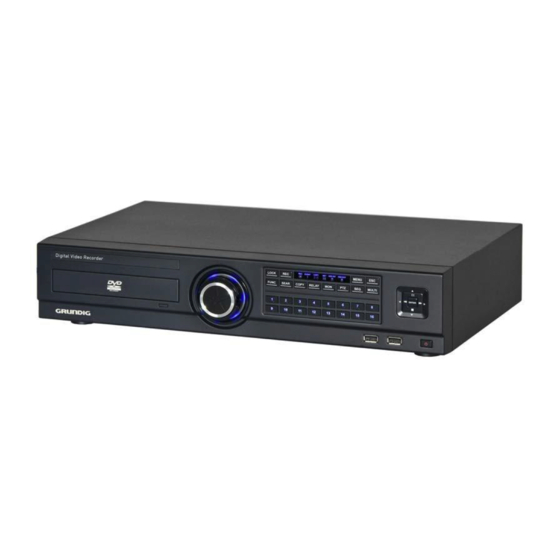
4. Installation 4.1. Part Names and Functions Front view: NOTE: Please note that the item with the number 1 (DVD‐Multi) is not available. English ... -
Page 11: Remote Control
Rear view: 4.2 Remote Control: It is possible to use all functions of the DVR with the remote control. If several DVRs are set with unique ID numbers, they can be controlled with one remote control. To use the remote control, it is necessary to set first the ID which you want to use. Keep pressing the ID button repeatedly (up to max. 16 times) and use it for matching DVR & ID. English ... - Page 12 English ...
-
Page 13: Setting The Remote Control
4.2.1 Setting the remote control Setting the ID of the DVR: When controlling several DVRs with one remote control, set the Remote Control ID as follows: (1) Press the [MENU] button. (2) Select “System” by using the [▶ ] arrow button and press [Enter] or the [▼] button. (3) Select “Utility” by using the [▶ ] arrow button and press the [Enter] button. (4) Select “Remote Controller ID” and press [Enter]. (5) Select a value using the [◀ /▶ ] arrow buttons and press [ESC]. (6) Press the [ESC] button to return to monitor mode. NOTE: Up to 16 DVRs can be controlled with a single remote control. If you do not use a remote control, set the Remote Controller ID to “All”. Selecting an ID with the remote control: If there are several DVRs with unique ID numbers, they can be controlled with one remote control. To select a specific DVR, keep pressing the ID button of the remote control until you hear a signal sound for the duration of 2 seconds. English ... -
Page 14: Installation And Connection
Operable range of the remote control: Loading the batteries into the remote control: The remote control requires two AAA‐type batteries. Please refer to the following installation steps. 4.3. Installation and Connection Check the settings: This DVR is a high quality security device with a high capacity built‐in HDD and important circuits. Before installation, please read carefully the recommendations below as high internal temperature of the product can lead to damages and shorten the product life cycle. Recommendations on installing a DVR in a rack: Do not seal the inside of the rack where the DVR is installed. Keep the airflow through the inlet and outlet. If there is another device installed in the rack, secure the additional space or install the air ventilation. Installation of an air circulation fan around each inlet and outlet is strongly recommended. (Install the filter around the inlet or outlet for harmful substances.) Keep the ambient temperature between 5°C~45°C around the DVR. Warnings if a HDD is installed: Please be extra careful not to damage the HDD as it easily breaks. English ... - Page 15 During installation, make sure the insulated coat does not come off or isnot placed in the wrong place. Do not lose screws and parts. (If screws and parts are not screwed or assembled correctly, the product may not operate) Check the HDD compatibility list HDD. The Partition table must be removed for the HDDs used in a PC or other DVR models before installation. HDD installation: * 1. Unscrew the bracket screws that are fixing it to the DVR. 2. Push the HDD bracket to a direction shown in the picture on the right and separate it from the fixtures. Lift the HDD bracket to a direction shown in the picture on the right and separate it from the bottom. ...
- Page 16 Place the HDD bracket fastened with screws into the DVR and fasten it on the bottom with screws. NOTE: Below is a SATA cable socket sequence of a mainboard. Up to 4 HDDs can be installed inside the DVR. Main Board Disk Manager Int A Int A Int B Int B Int C Int C Int D int D eSATA eSATA Adding a HDD: Remove the power cord before installation to protect the DVR against possible damage and an electric shock Please call the store you purchased the product from if it is not operating correctly due to installation or configuration mistakes. Warnings regarding Data loss: Please handle with care so the HDD data is not damaged. Check the HDD compatibility before installing an additional HDD. Be careful not to give any shock to the HDD during operation which could lead to possible damage or malfunction. There can be cases where the HDD and its data can be damaged. To minimize the data loss, please copy data as often as you can. Physical shock during disassembly or installation may lead to Data damage. Sudden power outage or turning off of the DVR can damage the HDD. Please do not try to move or shock the DVR while the HDD is working. Connecting the camera: Connect the CCTV camera to the DVR using the BNC cable as shown below: ...
- Page 17 5C‐FB(T), 5C‐HFB, L‐6CHD, RG6 about 180M HD‐SDI cable 5C‐HFBT about 200M HD‐SDI cable * Depends on the manufacturer and the model. <Warnings>: The transmission distance will be affected by cable types and the installation site environment. The transmission distance of the chosen cable will be various based on reduction rate of 750MHz (reduction rate of dB/100m < 25dB is recommended) A foamed or high‐foamed trishield cable is recommended. Impedance 75Ω must be used for coax cable connection and for the connector to work. Beware of deformation of the cable due to high pressure on the cable. Do not pull the cable with too much force. For DVR input/output, cables will be tied at the rear of the rack. If tied too tightly, the inside/outside insulator can be deformed so tie it loosely within the cable’s curvature range. For bigger distances, please use the GTH‐K0011E extender from GRUNDIG. Ex‐SDI: Cameras using the Ex‐SDI Technology are also supported by the GRX‐K4416A. Using Ex‐SDI, you can double the distance to transfer the signal between the camera and the DVR. Please note that the distance will also vary depending on the quality of the used cable. Connecting other devices: Connecting a monitor: Connect a CCTV monitor using a HDMI cable with the corresponding port. Connecting Audio: Connect the audio signal to the DVR using the RCA connector as shown above. English ...
- Page 18 Supplying Power: Connect the power cable as shown above. ‐ When supplying the DVR with power, the DVR starts booting automatically. ‐ In order to cut off the power, press the power switch on the DVR front for 5 seconds. When a pop‐up window appears, select “YES” to shut down the DVR. ‐ For supplying the DVR with power again, push the Power button. Connecting an external device: Connecting a USB device: The USB port can be used for copying of recorded data and for the mouse. See the table below for USB Device specifications. USB specifications Ver 2.0 or later Usable device USB Stick Voltage specifications DC 5V / Max. 200mA NOTE: The USB stick needs to be FAT32 formatted. The DVR may not recognize USB Flash memories that require an additional program on MS Windows. Connecting an eSATA Device : If an external eSATA storage is used, it can be connected to a rear eSATA port. Additional power for a eSATA device will be required as the DVR does not supply the power. ...
- Page 19 NOTE: 1. Check the compatibility of the eSATA with the DVR as not all eSATA are compatible with the DVR. 2. If an eSATA is connected to the DVR when it is on, it may not be recognised depending on the external devices. So we recommend following the steps below. 1) Turn off the DVR. 2) Turn off the eSATA then connect it to DVR. 3) Turn on the eSATA. 4) Turn on the DVR. Connecting input/out terminals: Wire end handling: See the picture on the right for wire end handling used in the terminal block. Please work differently on a single line and on a multiple line as they have different thicknesses. ‐ Multiple lines : Peel off the recommended length(8~10mm) and lead‐ coat it. Use AWG 22 ~ 26. ‐ Single line : Peel off the recommended length(8~10mm) and use AWG 20 ~ 26. Wire insertion/removal: As shown in the picture, push the lever to insert or remove a wire. English ...
- Page 20 Connecting a sensor: Specification: The requirements below need to be met in order to connect the sensor: Input Channel # 16EA Transistor input Input Type N.C, N.O support Specifications Supported sensor Dry contact sensor Connect the trimmed wire to Connection method terminal block Available input Minimum 500ms Performance Pulse range Output current Standard DC 12mA Connecting a sensor input terminal: Please see the picture for the sensor input. The picture below is an example of connecting a Dry Contact sensor type. Please refer to the section “Wire Handling” for more information. Connecting a relay: Specifications: Please see the table below for alarm output requirements. Output Ch. 4ch relay output Output type Dry Contact Specifications Connect the trimmed wire to ...
- Page 21 Connecting COM1 serial port with external devices: Connecting a text input device (ATM / POS / Access Control): Using COM1/RS232, TEXT DATA can be recorded with synchronising a POS/ATM. As shown in the picture, for a setting up to connect COM1/RS232 (D‐Sub 9pin), set up the serial & text info under “device” menu. Connecting a COM2/COM3 serial port external device: English 21 21 ...
-
Page 22: Different Configurations
Connecting a serial communication terminal to a PTZ device & Keyboard device: Control the PTZ devices and Keyboard devices by connecting them to the DVR’s COM ports. The picture in the right shows how a camera and a keyboard device with a PTZ function are connected to RS‐232 COM1 & RS‐485 COM2 respectively. Other serial communication terminals will be connected to other devices as shown in the below picture. To connect or remove a wire, please refer to the section “Wire end handling” and the supported models can be checked in from your supplier. Connecting the Serial Port to a Transparent device: Output Ch. 4ch relay output Output type Dry Contact Specifications Connect the trimmed wire to the Connection method terminal 30V / 1A Performance 125V / 0.5A Connecting a PTZ & Keyboard: Up to 255 DVRs can be connected. Using a keyboard and PTZ control is possible for all channels connected to the DVR. Also, multiple keyboards extension as Slave can be used limitless with a Master Keyboard. In this case, the Master Keyboard has the priority for all controls. Please refer to the instruction manual for PTZ keyboard connection & its way of control which comes with a PTZ/ Keyboard. Configuration using 2 serial ports: PTZ(DOME) and Keyboard can be connected to the DVR’s 2 serial ports. In such case, the keyboard can control the DVR and PTZ(DOME) at the same time, and the DVR can control the PTZ(DOME). ... - Page 23 Advanced configuration : Connection to an USB storage device for backups: Internet/Intranet configuration: English ...
-
Page 24: Running The Osd Menu
4.4. Running the OSD menu The OSD can be controlled with the keypad on the front panel of the DVR, with a remote control or with an USB mouse. In this manual we will refer to the keys of the front panel, as the procedure with a remote control and a mouse is almost identical. 4.4.1. OSD Menu Configuration Press [MENU] on the keypad on the front to open the configuration menu as shown below: ... -
Page 25: Basic Settings
4.4.2. Basic Settings Viewing Image: When powered on, the DVR starts automatically and displays a basic 4 ch‐split (GRH‐K1104B) , a 8‐split screen (GRH‐K2108B) or a 16‐split screen (GRH‐K4116B). NOTE: After booting the recorder, by default a prompt for entering the password will appear. The default admin password is: 1234. Setting Date & Time: ‐ Press the [MENU] button and select “System” when the OSD menu appears. ‐ Select “Date/Time” and press the [Enter] button. English ... - Page 26 Standard time zone Use the left or right arrow key on the front or the mouse wheel to select your time zone. (In order to go to the previous menu, press the [ESC] button on the front or click “X” with a mouse. This is the same for all OSD menus.) Daylight Saving T i me (DST) On the “time zone” setting, “on” will be chosen when users click on regions where daylight saving time applies and “off” will be chsoen when regions without daylight saving time are chosen. Users can check “off” if they don’t need daylight saving time function for a region where daylight saving time applies. Please select “custom” if users want to set their own daylight saving time preferences. Select “custom” and the DST setting will appear. “month/day” will set DST start/end at month/day/hour and “month/week/day” will set DST start/end to month/week/day/hour. NTP function Please set the NTP ‘On’ then select ‘Public’ in Client Mode for the DVR to set the time automatically via internet connection. ...
- Page 27 Continuous recording will automatically begin after booting is completed and continuous/event recording will begin according to the chosen program values. Manual recording Push the REC button on the front panel to begin/end manual recording and manual/event recording will begin according to the chosen program values. NOTE: If manual recording is chosen, exit the menu and check the manual record indicator on the status bar to confirm recording. If there is no manual recording indicator sign, press the REC button on the front panel to begin recording. Schedule recording Schedule recording will begin according to a pre‐set day/time schedule. Set day/time on “schedule setting” under the schedule recording mode. Program configuration Please set the resolution, frame rate, and picture quality of each individual camera per channel in “Program menu” under the record setup. <Reference>: How to check if it’s recording: When the settings are correct and recording has started, the “REC LED” indicator on the front will be flickering. Also, the status bar’s save indicator will show [SCHEDULE], [MANUAL], or [continuous] indicating that all channels are recording. The “REC LED” is turned off when the DVR is not recording. ...
-
Page 28: Menu Use
5. Menu Use 5.1. Menu Structure The menu structure is shown in the image below. The settings for each menu are explained in the following chapters. 5.2. Function Menu To run the Function menu, click the right mouse button in the live monitoring or playback status or push the “Func” button on the front panel. The Function menu enables every function of the product to be controlled by USB mouse. Each function can be executed by clicking the left mouse button. The Function menu can also be controlled by the front panel buttons. Please refer to the picture on the right for the Function menu structure.. Function Menu in Live Mode: Function Menu in Playback/Search Mode: English ... -
Page 29: Monitoring
6. Monitoring All HD‐SDI video image channels connected to the DVR are displayed on the screen after booting the DVR. 6.1. Basic Screen The basic screen shows a multi‐screen with all channels supported, if the multi‐screen has been modified and the DVR is being rebooted, the default multi‐screen will be shown. 6.2. Single Full Screen Mode After the power connection is established, the DVR will boot automatically. After booting, the user needs to put in his user password. In the default settings, only the admin has the rights to see the channels, therefore no user will see any video at the first boot. Depending on the model you will either see a 4ch or 8ch split view. Press the wanted channel number or click with the mouse on the wanted channel. Double‐click with the mouse to return to the previous multi‐channel view. You can select different multi‐channel views by clicking the [MULTI] button on the front panel or the [Display] button in the function bar. 6.3. Multi‐screen Mode Press [MULTI] for multi‐channel display or click the “Multi” function in the Function menu. Every time you press the [MULTI] button, the screen mode will change. For GRH‐K1104B you only have the 1‐4 channel multi‐view. For GRH‐K2108B you also have the 5‐8, 4C & 1~8 multi‐view and for GRH‐K4116B the 5‐8, 4C & 1~16 multiview . 6.4. Screen Description The status bar from the monitoring screen shows the DVR’s current status which includes Date/Time, Record, Motion/Sensor Detection, Manual Record, Text Input and HDD’s Record capacity. English ... -
Page 30: Sequence Mode
6.5. Sequence Mode Auto switch screen mode is a feature in which the selected channel or multi‐screen division switches in a sequence with the time interval of 1 – 60 seconds. (Please refer to “Monitor setup” for further configuration methods). Auto Switch mode can be set in every division mode by pressing the [SEQ] button. Press the [SEQ] button once more to exit the Auto Switch mode. 6.6. Event Screen Users can set the selected screen to pop‐up automatically when an event is triggered. Users can choose events that trigger the pop‐up from the event source. Event source supports 3 types of events: Sensor, Motion Detection & Text. If multiple events are triggered, the corresponding screens will pop up automatically. For example, if events are triggered in 3 Channels, they will be displayed in a 4 screen division automatically. To return to the original channel, press the button of one of the poped up channels. Press [ESC] to return to original channel. NOTE: If Alarm pop‐up is “Off”, Event pop‐up will not be enabled. If event screen switch is set to “Keep”, it keeps showing pop‐up image until the user presses a button. To return to the previous screen, please press any button. 6.7. Zoom Screen Mode By using D‐Zoom on a single screen, users can enlarge the section they want to view. Press [ZOOM] on a single screen in a full screen mode or press D‐Zoom while pressing [FUNC] to enable D‐ Zoom mode. Use “+,‐“ or drag a mouse to enlarge/reduce the screen. The initial location of the enlarged screen is the center. Use the direction keys to move the enlarged image 22 steps to left/right and 14 steps up/down. Enlarge mode can be used between a 1.00X ~ 10.00X range. To return to the previous screen, select a button and press enter or left click the mouse. 6.8. Pause Live Screen Just like in playback, Live screen can be paused. ... -
Page 31: Ptz Control
6.9. PTZ Control Connect a PTZ controller to the DVR and set the relevant protocol in the “Serial Setup” menu and the corresponding camera menu, then the PTZ of the camera can be operated while live monitoring is activated. To pan and tilt a PTZ camera, use the direction keys from the DVR’s front panel or the mouse. You can access focus, zoom and presets of the PTZ camera by pressing the PTZ button on the DVR’s front panel or clicking on the PTZ icon in the Function menu. Below you find a list of supported protocols. Instant PTZ PTZ mode will automatically be on if Instant PTZ switches a set channel to a single screen. + sign will appear in the middle of the screen if PTZ is operating. ‐ Press the button of the desired channel, or select the channel with the mouse. ‐ Press the PTZ button from the front panel or click on the PTZ icon in the Function menu with the mouse. ‐ The PTZ menu (Zoom/Focus, Load Preset, Save Preset) will appear. ‐ Then press the [Enter] button or click on the mouse. 6.9.1. Pan/Tilt The Pan/Tilt function is directly activated after you have chosen a PTZ camera in single monitor mode. You can control the PTZ with the front panel direction buttons, or with the USB mouse by clicking on the screen. Depending on the distance to the central cross, the PTZ will move into the direction of the mouse click. 6.9.2. Zoom/Focus This menu is used to control the Zoom & Focus function in real‐time monitoring mode. ‐ Select Z/F (Zoom/Focus) from the PTZ mode. ‐ Control Zoom/Focus through the direction keys on front of the DVR or use the scroll wheel of the mouse. English ... -
Page 32: Loading Preset
6.9.3. Loading Preset This menu is used to move the PTZ camera into a Preset position during real‐time monitoring mode. ‐ Use the Up / Down buttons or the mouse wheel to select the Preset Number. ‐ Once Preset is configured, please select [Load] and then press [Enter]. 6.9.4. Save Preset This menu is used to set a new Preset position during real‐time monitoring mode. ‐ Control the PTZ camera location by using the ‘Pan/Tilt’ menu and the ‘Zoom/Focus’ menu. ‐ Use the Up / Down buttons or the mouse wheel to select the Preset Number. ‐ Once the preset position is configured, select [Save] and then press [Enter]. 6.9.5. Auxiliary On This menu is used to utilise specific functions of a PTZ device during real‐time monitoring mode. ‐ Use the Up / Down buttons or the mouse wheel to select the Aux Number. ‐ Select the relevant Number button for this specific function (Up to 16 functions of the PTZ camera can be controlled with the Aux Function.) 6.9.6. Auxiliary Off This menu is used to stop operation of a specific function of the PTZ device. ‐ Use the Up / Down buttons or the mouse wheel to select the Aux Number. ‐ Select Off and press the [Enter] button or click on the mouse. 6.10 Camera Setup Used to enter the menu of the connected PTZ device. Use the direction keys and the enter button to set up the menu. Press esc or “ x ” to exit the menu. English ... -
Page 33: Implemented Ptz Camera Protocols
6.11. Implemented PTZ camera protocols: English ... -
Page 34: Playback/Search
7. Playback/Search 7.1. Playback/Search Mode 7.1.1. Playback on Standard monitor (16 / 9 / 4 division) ‐ Please press the [SEARCH] button in monitoring mode or click the [SEARCH] button in the Function menu with the mouse. ‐ When pressing the [PLAY] button or the [FWD] button, the video plays in forward direction at 1× speed. ‐ When pressing the [REW] button, the video plays backwards at 1× speed. ‐ When pressing the Playback button in a multi‐division monitor mode, it plays the recorded data for all viewable channels. 7.1.2. Playback function PLAY ◀ ▶ : Playback 1× speed Multichannel video will play when pressing the [PLAY] button in Multichannel monitor mode. PAUSE ll : Pause the video temporarily. STOP ■: Stops the Playback and the DVR returns to live view. FWD ▶ ▶ : Playback speed will be changed (x1, x2, x4, x8, x16, x32, x64, x1/2, x1, x2, x4 – in order). When pressing the [FWD] button in live view mode, the DVR plays back the recorded video from 1 minute ago. Playback speed can be changed by pressing the [FWD] button. ... -
Page 35: Screen Composition/Names Of The Functions
7.1.3. Screen composition/names of the functions: Screen composition Name Description Playback button Use the buttons to control the playback. Screen Displays the playback videos. Log viewer Displays the log seen on timeline Calendar/time Select a date on the calendar to view the data of the date. search Timeline Displays the info of the unit and search the playback sections. Channel Selector Allows you to select the channels that will be displayed Icon function description: ... -
Page 36: Copy
Calendar search: When calendar search is running, it marks the dates on which there were recordings. Select a date from calendar you want to search, and it moves to the desired date. Event search: Event info(All, Motion, Sensor, Text, None) is shown on the timeline. Select a list to move to the selected time. Channel Selector: Select between all channels or a selection to be displayed in the monitor and timeline. 7.2. Copy The Copy function is used to back up video material on USB devices and to store it on a FAT32 formatted device. In the user authorisation you can define which user has the right to back up the video. For this please refer to chapter 8.1.3. User Setup. To use the copy function, press [COPY] or click the Copy button in the Function menu. NOTE: The multi‐channel format always includes a miniplayer.exe file that can play back the video without the need to install any program. You have also access to the logfile with this miniplayer. NOTE: When accessing the Copy function from Playback, the actual playback time will be copied to the ... -
Page 37: Exe
7.2.1 EXE The EXE format can be backed up on external HDDs and USB Flash drives. Together with the video a Mini player will be copied to the Storage device to be able to view the EXE format. You can also open the EXE file with the GRUNDIG Control Center. Select the channel you want to record and press [Enter] or use the mouse to open the channel selector as shown below. Type: Select EXE using the direction keys or the mouse. Channel: Select the channels you want to back up. From: Set the start date or time to copy. Use the direction keys or the mouse to change the values. To: Set the end date or time to copy. Use the direction keys or the mouse to change the values. Select disk: Select the media you want to copy to. Press [Enter] on the Disk list or click the mouse. Start: Starts the backup. Press [Enter] or click the mouse. Format: This will format the entered USB device. All data on the device will be deleted. NOTE: If the backup is interrupted, the backup files will not be playable on a PC. English ... -
Page 38: Configuration
8. Configuration 8.1. System Setup Time, Disk and Authority settings and miscellaneous settings can be configured here. 8.1.1. Date/Time The Date and Time setting should be configured prior to any recording. The Time configuration is very important to protect the recording data. Changing the time during recording is not recommended. The factory default setting for the time is “UTC 00:00 Dublin”. Time Setup: Caution: While recording, changing the system time will affect a time change for all previously recorded video data. Therefore, we recommend to back up the recorded video before changing the system time. ‐ Press “Main Menu” in the Function menu or the [MENU] button on the front panel. ‐ Select the “System” menu. ‐ Select “Date/Time” in the System menu. The Date/Time configuration will be opened. ‐ Use the directional keys or the mouse to change the values. Time Zone / Standard Time: Use the Left / Right direction keys or the mouse wheel. To return to the previous menu, press [ESC] or click the right mouse button. Daylight Saving: This menu is synchronised with the time zone configuration menu. When a daylight saving area is set, this function is activated. The daylight saving applicable area is working in conformity with the time zone of Microsoft Windows. Custom DST Setup: English ... - Page 39 You can also use a custom DST. Select a fixed day of a week (first Tuesday of March) or the day of a month (24th of March) to select when the switch should happen. You can also define the exact time, when it should happen. This can be used if you want to change the time not in the middle of the night, but maybe on the noon of the next day, so you have enough time to search for any events using the “old” time, for example. Date format (Type): Change the date format between “MM/DD/YYYY”, “YYYY/MM/DD” and “DD/MM/YYYY” by using the Left / Right direction keys or the mouse wheel. Start / End Time: With the Left / Right direction keys, you can move to year, month, day, hour in order. Each configuration can be changed with the Up / Down direction keys or the mouse wheel. NTP Setup / Set Automatically (NTP): The NTP (Network Time Protocol) synchronises the time of all connected devices. The DVR can be set to client mode or server mode or to both modes at the same time. Sync with NTP: Enable or disable the NTP function. NTP Mode: Configure the NTP mode of the DVR – Client / Server / Both English ...
-
Page 40: Disk
NOTE: When using the NTP client mode, the user must set the NTP to "On". NTP Server Loc.: If the DVR is in client NTP mode, this function is enabled. Configure the IP address of a local network NTP server or select “Public” if the NTP server is a public one. NTP Local server IP: Input the IP address of the local NTP server or a DVR that is working in NTP server mode. Interval: Configure the interval of the time synchronisation. 8.1.2. Disk In the “Disk” menu everything regarding the hard disk of the DVR can be configured. Here you can also use the Disk Manager to format HDDs. Overwrite (Auto Deletion): If there is no space left in the HDD, old data will be overwritten automatically. English ... - Page 41 Delete Data: Select this ticker to select after which amount of days the recorded data will be deleted. Instant Playback: Decide the time interval that will be used to go back in time when you select the instant playback function. Disk Manager: “Disk Manager” is the menu for the management of internal or external HDDs (hard disk drives). You can see the type, name, the bad block status and the size of the HDD in this menu. You can also select if the HDD is enabled for recording or not. NOTE: If you enable a HDD to record, you will be asked whether the HDD should be formatted. Type: Displays the location or type of disk ( Int A (Internal A HDD), Int B (Internal B HDD), Ext (External HDD) ). Model: HDD model name Bad Blk: Displays the number of bad blocks of the HDD. Size: Displays the HDD size in MB. English ...
-
Page 42: User Setup
Enabled: Shows if a HDD is enabled for recording (“Yes”: Enabled / “No”: Disabled). To enable a HDD, select it and change and press the [Enable] button on the bottom of the disk manager. If the HDD needs to be formatted, select [Format] first. All data will be erased then. 8.1.3. User Setup The user setup is only editable for the administrator. Users can only change their passwords here. In the user setup you can define which user has which rights. You can choose that users are only allowed to access defined channels and can only execute defined functions. Here you can change the user name and the password. User : Here you can select which user you want to edit. Change ID & Password: Change the user name here. This name can then be used to enter the DVR directly or over the Ethernet connection. Change Password: The password can be up to 8 digits long. To ensure you did not misspell the password, you have to enter the password twice. Press ”Change” when the password is finished. After that, a message window will be shown and you have to confirm the password change. English ... - Page 43 NOTE: The Admin Password is “1234” in factory default. For user 1 to 10 the password is (in order) “1111”,”2222”, ... and for user 10 it is “0000”. Access rights: Here you define which rights the user has. The administrator has always all of the rights and this cannot be changed. In the default settings the users do not have any right to see any channel or do anything. The administrator needs to give them rights first. Action rights: Here you can define which functions of the DVR the user can access. Menu: Gives the user the right to access the configuration menu. (The users are not allowed to change the user rights or to perform a factory reset.) PTZ: If set to YES, the user has the right to control PTZ cameras. Relay: If set to YES, the user has the right to activate the relays of the DVR. Playback: If set to YES, the user has the right to access the Playback. Power Off: If set to YES, the user has the right to turn off the DVR. Copy: If set to YES the user has the right to backup video. N/MIC: If set to YES, the user has the right to use the microphone function over the network. English ...
- Page 44 Channel rights: Here you can define which channels the user can see under Live & Playback. Covert channels will also be invisible in search results and backup files. Additional User Setup: In the Additional User Setup extended functions can be accessed. 2‐Men Security: Activate this function to enable the 2‐men security function for this user. You will need to enter a second password for this user to log in. Auto Log‐out (Min): Every user can have its own auto‐log‐out time. With this function you can, for example, limit the admin access to 2 minutes. So even if you forget to log‐out, the access to the DVR will not be possible without the admin password. But you can also create a user with infinite log‐out time (set to 0), so that you can have a “guest” account that will show defined channels all the time without any special function rights. Block Playback: Here you can block the playback access independently for each user. Select days, hours and minutes for the user he is allowed to access the recorded material. NOTE: If a user is logged in locally with blocked playback access. Also from remote the playback time is blocked, even though the remote user, might have a different time range he can access. Auto Login: The Auto‐Login function can be used to log in a user automatically. Use this function to restart the DVR in a guest mode, with limited access for example. English ...
-
Page 45: Utility
8.1.4. Utility Configure the name of the DVR, the remote control ID and Language. DVR Alias: Set the name of the DVR. This name will be shown when accessing the DVR via a network. Language: Select the language you would like to use. Key Buzzer: Select if the Buzzer will be active, when you press a button on the front panel of the DVR. DVR Keyboard ID: This menu is for setting the address of the keyboard when using all functions of the DVR with the keyboard. Factory default is “1”. If the user wants to control various DVRs with one keyboard, each address should be set with a different value. Remote Controller ID: Maximally 16 remote control IDs can be set. One remote control can be used to manage all the 16 DVRs. Registration order for the remote control: 1. Make the remote control point in the direction of the DVR. 2. Press the ID button several times to match the ID of the remote control to the DVR. 3. If the IDs are matched correctly, the DVR buzzes. 4. Now you can use the remote control. English ... - Page 46 System Information: The System information contains all the relevant system information like firmware and model type. System Log: The system log shows the boot status of the system and any changes regarding users and the DVR configuration. You can also export the system log to USB disk from here. Firmware Update: You can update the firmware by a USB Memory device. ‐ Insert a USB memory device including the firmware file to the USB port. ‐ Press the Firmware Update button. ‐ Select [YES] in the pop‐up window. NOTE: Only the administrator is allowed to perform a Firmware Update. ‐ The system will reboot. ‐ Firmware update is done. English ...
- Page 47 Factory Reset: Set all configurations back to factory default. NOTE: Only the administrator is allowed to perform a factory reset. Import/Export Configuration: Use this function to backup the DVR configuration for a later time, or to copy it to other DVRs of the same model type and firmware status. English ...
-
Page 48: Network
8.2. Network This is the menu for configuring the network related settings. 8.2.1. Network Type: Configure the type of Network (Ethernet/xDSL) connection. If the DVR is connected to a local network, you can change the configuration directly in the fields below. If the DVR is connected by xDSL (PPPoE), please make the configuration in the xDSL submenu. Automatic Addressing (DHCP): With DHCP (Dynamic Host Configuration Protocol), all hosts connected to LAN can get a temporary IP address from a DHCP server. If the LAN has an active DHCP server, this server allocates the IP address directly to the DVR. If there is no DHCP server in the network, the IP address needs to be configured manually. IP Address: The IP Address is for connection between the DVR and the Control Center and also for the web connection with the WebViewer (Net Mask and Gateway need to be configured if you want to access the DVR over the Internet.) Net Mask: The Net Mask determines the range of the IP addresses which are available for use. You should receive the correct data from the network administrator. Gateway: The Gateway is necessary for different types of network connections. You should receive the correct data from the network administrator. UPnP (Universal Plug and play) Port Forwarding: This very helpful feature can be used if you do not want to configure your network forwarding ports manually. If activated, the DVR will instruct your router automatically to forward all requests coming to the defined port. Set the Port Forwarding to “On” to activate this feature in the Pop Up Window. The status of the UPnP forwarding will be shown in the Status field. English ... - Page 49 DNS Server: DNS is a network service used to rename IP addresses (Domain Name Server) and it should be received from the network administrator. Port: The port is necessary for the connection to the Control Center Software and the WebViewer. The factory default setting is Port 80. If you want to connect to the DVR through the internet over a router, this is the port you will need to forward in your router. Please make also sure that your firewall is not preventing the access to this port. Bandwidth Limit: In this menu the bandwidth used for video transmission can be limited. You can define the bandwidth between 0.03 Mbps and 99.99 Mbps. Contact the network administrator for further information on bandwidth limitation. Video Streaming: Adjust the RTSP streaming settings here. Choose the RTSP port and deactivate authentication if needed. English ...
-
Page 50: Ddns
IP Filtering: Configure a White‐ or Blacklist to filter IP addresses for remote connection. 8.2.2. DDNS If the DVR is connected to a Cable modem or a xDSL modem, the IP address will be changed with every connection to ISP. To connect to the DVR over the Internet you need to know this IP address. GRUNDIG supplies a DDN Server that can be used to update the IP address of the DVR. The DVR sends its latest IP address to this server and the user can then connect to this server to access its DVR. To register the Static IP to DDNS, please refer to the following configuration. Host Name: This menu shows the server address where the DVR registers its dynamic IP address. The DDNS address, on which GRUNDIG is operating now, is: www.grundig‐ddns.eu. You can access the DVR now over the internet and the Control Center Software through the following address: [last 6 digits of the MAC address].grundig‐ddns.eu English ... -
Page 51: Radius
(example: g02c362.grundig‐ddns.eu) Custom DDNS: If you have already a DDNS service like no‐ip.com, you can use this account also with your Grundig DVR. You have to enter your Host Name, user ID and the password to use this function. The MAC address is printed on the box label and on the backside of the DVR. 8.2.3. Radius Remote Authentication Dial In User Service (RADIUS) is a networking protocol that provides centralized Authentication, Authorization, and Accounting (AAA) management for users that connect and use a network service. Here you can configure the Radius settings if you are using this protocol in your network. English ... -
Page 52: Device Setup
Caution: NTSC and PAL cameras cannot be used at the same time. If changing the camera type from NTSC to PAL, the system should be rebooted. 8.3.1. Camera Setup Select the camera you want to configure, by selecting its channel. Name: Fill in the name the camera should have. This name will be shown on the monitor and will be also shown in the GRUNDIG Control Center Software. When pressing the [Enter] button or clicking the mouse, you can enter the camera name in the text menu. English ... -
Page 53: Monitor Setup
8.3.2. Monitor Setup Configure all connected monitors. Depending on the model of the DVR and the attached monitor different options are available. Sequence configuration: Here you can configure the user sequence. You can edit up to 16 steps within an interval from 1 to 60 seconds. You can select a single channel and Multi‐Mode views. Sequence Interval: Select the amount of time in seconds between the switching of channels during sequence. 8.3.3. Audio Setup English ... - Page 54 In this menu the user can configure Audio recording, Volume, Synchronisation and Mixing. Audio Channel: Select the channel you want to configure. Video Channel: Select the video channel you want to connect to this audio channel. Audio REC: Enable or disable the audio recording. If disabled, audio will be transmitted in live view, but will not be recorded. If audio recording is enabled, the recorded audio will also be available in playback mode. Audio Gain: Configure the volume of the audio in the + /‐ direction. Audio Output Channel: Select the channel that will be active over the speakers. You can either fix one audio channel, or let always make audio channel active that is connected to the current video channel. English ...
-
Page 55: Text Setup
8.3.4. Text Setup Device: Select the type of the Text input device you are using. Choose between VSI‐Pro Hydra, Starfinger 007 or manual configuration. If you choose the manual configuration you have to set the Header, Delimiter, Timeout and Lines settings. Sync Video Channel: Select the channel which will be synchronised with the text input. Recording: Enable or disable the recording of transmitted texts. Seek Header: Activate or deactivate searching for the header of the data. You can define up to 2 different headers here. For information about the header, please refer to the manual of your text input device. Delimiter: The delimiter value may differ depending on the device used. For more information on delimiters, refer to the user manual of the text input device. Timeout: The lines defined below are the maximum number of text lines available for one piece of data. Even though the number of lines is preset the actual number may differ sometimes. For example, three lines are programmed for a client name input for an ATM, but if someone registers only his/her first name and last name, only two lines will be provided when the person uses the ATM. The DVR will not be able to detect this automatically, so the Timeout function will be used to stop data recognition after the last line is entered. Lines: This defines the maximum number of lines for one piece of data. NOTE: If the external text input device cannot be recognised, please contact the seller of the external device. English ... -
Page 56: Event Setup
8.4. Event Setup In this menu users can configure the handling of an event. 8.4.1. Event Check Enable or disable the event checking algorithms. You can set up a schedule for the event check if you want to enable the event check only for a certain time frame. In the case of schedule mode, you can set up schedules for different dates and times, as shown in the following screenshot. Create a schedule: By default the DVR has set the event schedule for all days at all times. To edit the exiting schedule, you have to delete the exiting schedule first. Then you can add new schedules by creating them in the Add Schedule field and press the [Add] button when you are finished. You can add schedules for each day or for weekdays and weekends. English ... -
Page 57: Event Actions
8.4.2. Event Actions Configure what action the DVR will perform if an event is detected. Event Action: There are different actions you can choose from: Relays, Buzzer, FTP, E‐Mail, Video Pop Up, System Alarms and Camera Presets.. Action Duration: Select how long an Action Duration will be kept up. Relay and Buzzer can be configured from 5 seconds to 60 seconds. In the FTP, E‐mail and Twitter notification you can configure the repeating interval. Event Sources: There are multiple different event sources available that could trigger an event. The amount of these sources differ for each model, but they all have following types. ... - Page 58 E‐Mail Setup: Here you can set up the sender & receiver E‐mail address. Recipient Address: Input the E‐mail address to get an event alarm to this E‐Mail address. Sender Address: Not mandatory, but necessary if the receiver wants to know which DVR sent the event. Attach Picture: Tick this box, if you want to receive a picture of the channel that triggered the event. SMTP Server: Address: Enter your SMTP server address, provided by your email address provider. ID: Enter the username for your email address. Password: Enter your email password. SMTP Port: Enter the port your SMTP server is using. This information can also be obtained from your email provider. Authentication: Please select here if your SMTP Server needs an authentication. You can also choose if your SMTP Server is using a TLS encryption method. FTP Setup: Here you can set up all information needed to upload events to an FTP server. English ...
-
Page 59: Motion Detection
Server IP/URL: Input the URL to connect to the FTP server. Please use either a DNS name or the static IP address. FTP directory: If you want to include all the uploads in a dedicated directory please name it here. Make sure the directory exists on the FTP server. User ID: Please input the user name which will be used to access the FTP server. Password: Please input the password of the above user. 8.4.3. Motion Detection Video Channel: Select if you want to configure all channels or only a dedicated one. Sensitivity: The sensitivity of the motion detection can be configured from min. 1 to max. 10, whereas 1 means less sensitive and 10 means very sensitive. Change Area: A custom area can only be defined for a single channel. The video is divided into 15x10 grids. After pushing the custom area button, the configuration window for the detection area will appear. English ... -
Page 60: Sensor
Select an area with the direction keys and press [Enter] or click the mouse to select or deselect an area which is used for motion detection. The first selected field will define the start and the second one will draw a rectangle within these 2 fields. Combine several rectangles to optimise the Motion detection area. Press the [ESC] button or click the right mouse button to apply your settings and go back to the previous menu. 8.4.4. Sensor This menu is to set up the existing sensor input and the type of the sensor. GRH‐K4116B has 16 inputs, GRH‐K2108B has 8 inputs and GRH‐K1104B has 4 inputs. The sensors can be set either to Normal Open (N.O.) or to Normal Close (N.C.). English ... -
Page 61: Recording Setup
8.5. Recording Setup There are 3 modes for recording – Continuous Recording, Manual Recording & Schedule Recording. Schedule Recording records according to a configured schedule, you can use different programs for different times.. Manual Recording records only after pushing the [REC] button or an event is noticed, continuous recording will record all the time and can switch the recording mode when events are detected. 8.5.1. Continuous / Manual / Schedule Recording Setup Continuous Record: If the DVR is set to Continuous Record the DVR will record all the time. If an event occurs the recording setting will be changed from continuous to event settings. Manual Record: If set to Manual Record, the DVR will record when pressing the [REC] button. It will stop recording when you press [REC] again. If an event is detected the DVR will start recording automatically. You can also set which program is used for manual recordings. English ... - Page 62 Schedule Record: The DVR can record automatically, depending on the programmed schedule. Set the recording mode to Schedule Record and configure the days and time in the schedule submenu. Select the days and the time zones which you want to record. You can also select different programs for different times. ‐ Program: Set the recording program (A~Z) ‐ Time: Set the applicable time ‐ Day : Set the day you want to record English ...
-
Page 63: Program Setup
‐ Program: Set the program you want to use for this day and time ‐ Delete selected: will delete the currently selected index ‐ Delete All: Wll delete all indexes that are in the schedule list. 8.5.2. Program Setup Here you can setup the recording resolution, frame rate and quality for every channel for normal recording and for event recording. Program: There are 9 programs from A to I composing the recording quality and resolution per channel. For a detailed explanation please refer to the program configuration below. Video: Displays the channel number. Maximum FPS: Displays the maximum possible frames per second you can use for this channel. F (FPS): FPS means frame per second. The user can select a frame rate from 1 to maximum fps. The max. frame rate can differ according to the configuration. Q (Quality): There are 7 recording qualities: Q7/ Q6/ Q5 / Q4 / Q3 / Q2 / Q1. The recommended quality for event recording is Q5. Q1 has a low quality which needs less storage space and Q7 is a higher quality which needs more storage space. English ... -
Page 64: Grundig Web Viewer
NOTE: If you disable a channel or lower its resolution or its frame rate the unused bandwidth can be used for other channels to increase their frame rate or resolution. The relation between general recording and event recording: When an event is triggered, the DVR records with the event recording settings. The recording performance of the DVR differs for every model. Quick Settings: Here you can apply the selected FPS and Quality to all channels at once. 9. GRUNDIG Web Viewer The GRUNDIG WebViewer is a Web application program to access the DVR over an Ethernet or Internet connection. You can monitor the live view or access the recorded data with this program. The GRUNDIG WebViewer is divided into the Login page, the Monitor page, where you can monitor the live video, and the Playback page to access recorded videos. 9.1. System Requirements 9.2. Login After inputting the IP address of the DVR, the GRUNDIG WebViewer Login page will be displayed in the browser window. English ... -
Page 65: User Setup
Input the User ID and Password and click ‘LOGIN’ to access. If the user/administrator did not change the password in the Control Center, the ID and the Password will be: ID: admin / user1 / user2 / … / user10 Password: 1234 / 1111 / 2222 / …/ 0000 9.3. User Setup To access the GRUNDIG WebViewer, user authority and password can be changed in the DVR or in the Control Center configuration (see the following images). The basic admin password is “1234” and the user password is “1111“ for User 1, “2222” for User 2 etc. The English ... -
Page 66: Available Browser
This authority configuration is almost the same in the DVR as in the Control Center. But the authorisation of quick recording and the covering of dedicated channels for a user are only possible in the Control Center. 9.4. Available Browser The GRUNDIG WebViewer is optimised for the Windows Internet Explorer 6.0 or higher. But GRUNDIG also supplies a Java based access to the DVR that can be used with other browsers like Mozilla Firefox, Apple Safari, Google Chrome or the Opera browser. WebViewer Installer: The Login page provides a manual installation program for the WebViewer. A PC that accesses the WebViewer for the first time will install an ActiveX certificate to use the WebViewer’s functions. If this installation fails, the installation program can be downloaded from the Login Page and installed manually. Caution: When installing the WebViewer Installer, all programs related to the Control Center have to be closed. Otherwise the installation might fail. 9.5. Monitor When successfully authorised with User ID & Password input at the Login page, you will be directed to the Monitor page. On the Monitor page you can view live videos of cameras connected to DVR, or you can control a PTZ camera, Relays, and use the Microphone function according to user’s authorisation. English ... -
Page 67: Screen Division And Changing Video Position
9.5.1. Screen division and changing video position When accessing the Monitor page for the first time, 9 divisions, 16 divisions or 32 divisions (according to the number of channels of the DVR) are displayed. You can change to 1, 4, 9, 13, 16, 25 or 36 divisions by clicking on the number on top of the page. Also, you can change to 1‐channel mode by clicking on any of the channel images. English ... - Page 68 Double‐click on one of the channels to switch to 1‐channel mode. After entering 1‐channel mode, a double‐click on the screen will return to the previous division of channels. On the division screen, you can change the screen location. If you want to move channel 3 to the position of channel 6, drag the 3ch image and drop it on the 6ch location. Channel 6 will automatically move to the former position of channel 3. English ...
-
Page 69: Playback On Standard Monitor (16 / 9 / 4 Division)
9.5.4. Sensor Indication The icons indicate whether a sensor event occurred in the system. When a sensor is activated, the relevant sensor icon will change to red colour. 9.5.5. Relay operation You can turn on or off the relays of the DVR within the WebViewer. Click the number button to activate the relay and the icon will change from blue to orange. If you define a time for the relay in the Control Center, the Control Center will be turned off automatically after this configuration. Activating relays is only possible when the user possesses the authorisation. Refer to the chapter “User Authority” in this manual for the setup of user authority for relays. 9.5.6. Using a microphone You can enable or disable the use of a microphone within the GRUNDIG WebViewer. The default setting is Off. If a microphone is activated, the colour of the corresponding icon will change from blue to red. English ... -
Page 70: Event Data
9.5.7. Event Data The event log is displayed at the bottom of the monitoring page and shows all the event information stored on the DVR. 9.5.8. Relay operation The indicated data is listed as follows: [Table / Event Icon] 9.5.9. Video Recording & Safe Saving Video Recording: During monitoring, the GRUNDIG WebViewer can record up to 10 minutes of video by clicking the Quick Recording button (the red dot in the top panel). During Quick Recording, the recording time is shown on the video. During video recording, click the Quick Recording button to stop recording and a dialogue box will be opened to store the recorded files. Saved recording files are saved in “*.re4” file format. The .re4 file can be played back by the GRUNDIG Control ... -
Page 71: Using Ptz
9.5.10. Using PTZ Among the icons on the top of a video in monitoring mode, click ‘PTZ’ to activate the control Pan, Tilt, Zoom, and Focus. If a PTZ camera is connected and already set to PTZ, this button is activated by default. Pan/Tilt Control: To control the PTZ with the mouse, click the right button and select “PTZ” or click the arrow button at the top. A Cross line on the middle of screen will be shown indicating that PTZ control is activated. Click within the image to operate the pan/tilt function. Zoom/Focus Control: Move the mouse to the left and right edge to see the slide bar for Zoom and Focus. Move to Preset: In case you have a set preset for a PTZ in the DVR, you can access it by right‐clicking the mouse and selecting “Go to Preset”. When selecting a preset position from the preset list, the camera will move to the selected preset position. Activating Auxiliary: In case of a preset set, the “Auxiliary” function is indicated additionally, and can be operated after you selected the designated menu. NOTE: For a supported PTZ camera list please refer to 6.9. PTZ Control. 9.5.11. Using Audio In case of Channel setup synchronisation with Audio, press the right mouse button on the channel to activate the pop‐up menu “Listen” or activate the audio listen button. In the default setting the audio is muted. To activate the audio transmission, select it in the pop‐up menu or click the corresponding button. ... -
Page 72: Playback
You can disable and enable channels by clicking on the corresponding button at the top of the screen. 9.6. Playback If you have the user rights to play back video, you can access the Playback screen when pressing the “Go” button on the Monitor screen of the GRUNDIG WebViewer. In the Playback screen you can monitor up to 16 video streams simultaneously and search through a calendar to see recorded video from that date. You can make backups of the videos and save images in .bmp format or print them directly. 9.6.1. Video Division & Changing Channel The Playback supports 1, 4, 9 and 16 divisional screens. You can select the number of divisions using the menu on the top of the page as shown in the picture above. If the screen shows 4 divisions CH1~CH4, you can change to CH5~CH8 using the ‘Next’ button. Press the ‘Prev’ button to call for the previous channel group CH1~CH4. 9.6.2. Image recording English ... -
Page 73: Printing
You can save a playback image as ‘.bmp’ picture file. Select the channel with the mouse and click the ‘Save’ button. A Save Image dialogue box appears and you can input a memo text or select if the channel name, date and event data should be written unto the file. Press ‘OK’ to open the dialogue box for the saving location, then you can save it as a ‘.bmp’ file. 9.6.3. Printing Select the channel you want to print, and click the ‘Print’ button. A window pops up to input a memo text. Click the ‘OK’ button to print the image on the connected printer. The Printout will include the ‘Printing Date’, ‘Channel name’, ‘Recording Date’, ‘Event’ and the ‘Memo’ text. 9.6.4. Backup You can choose between .re4 (multi‐channel) or .avi (single‐channel) backup. Select the time, date and channel you want to back up und choose a location to save the file to. If you want to secure the video file you can input a password which has to be verified. ... -
Page 74: Web Monitor
9.6.5. W eb Monitor Click on the ‘Go’ button at the top of the page to return to the Web Monitor page. 9.6.6. Channel On/Off This function is similar to the Channel On/Off function of the Web Monitor. 9.6.7. Saving Time & Checking Rec. Capacity This field indicates the total capacity of the HDD and also displays the Starting date & Last date of the recorded video on the DVR. The image shows the percentage (%) of the DVR’s HDD capacity. 9.6.8. Searching in the Calendar When a video was recorded on a special date, that day will be coloured in black. When a day is coloured in grey, this means that there was no video recorded on this date. Select the year, month, day and time to play back the video of that date. When clicking on the ‘Go to’ button, you get access to the 24 hours of that date. 9.6.9. Functions at the bottom of monitor (1) Indicates the playback range of the recorded image. English ... -
Page 75: Java Based Web Viewer
(7) Here you can set if audio should be played or not, and you can change the volume. 9.7. Java based Web Viewer The GRUNDIG DVRs also support a connection based on Java. This technology can be used to get access to the DVR using another browser than the Microsoft Internet Explorer. The user just needs to select "Java" in the WebViewer start page. While the opticaldesign looks slightly different than ActiveX, the basic functions are almost identical. You can have Multi‐Views in Live mode, controlPTZ cameras and activate the relays over a network ... - Page 76 To log‐in, please enter the ID and the password, select the resolution, the channel number and the refresh rate. Press the [Start View] button or [0] on a mobile phone without a touch screen to start the monitoring. English ...
-
Page 77: Monitoring Page
10.2. Monitoring Page The monitoring page shows the selected channel video and some functions you can use, right below the video display. The functions can be activated by pressing the buttons (touchscreen devices) or pressing the corresponding number on your phone keypad. For the functions, please refer to the description below. (0) MENU : Move back to Login page (1) CH‐ : Move to previous channel (2) UP : If the channel is PTZ you can move the camera up (3) WIDE : If the channel is PTZ you can zoom out (4) <‐ : If the channel is PTZ you can move the camera to the left (6) ‐> : If the channel is PTZ you can move the camera to the right (7) CH+ : Move to next channel (8) DN : If the channel is PTZ you can move the camera down (9) TELE : If the channel is PTZ you can zoom in English ... -
Page 78: Ec Declaration Of Conformity
EC Declaration of Conformity 16 Channel H.264 Hybrid‐ GRX‐K4416A Recorder It is hereby certified that the products meet the standards in the following relevant provisions: EC EMC Directive 2004/108/EC Low Voltage Directive 2006/95/EC AIMD Directive 90/385/EEC R&TTE Directive 1999/5/EC Applied harmonised standards and technical specifications: EN 60950‐1 (2006 +A11:2009+A1:2010+A12:2011) EN 55022 (2010) EN 55024 (2010) EN 50130‐4 (2011) EN61000‐3‐2 (2006/A2:2009) EN 61000‐3‐3 (2008) ASP AG Lüttringhauser Str. 9 42897 Remscheid Germany Remscheid, 18.12.2012 ... -
Page 79: Open Source License Report Of The Product
Open Source License Report on the Product The software included in this product contains copyrighted software that is licensed BSD License : ash, miniupnpc, telnet‐server, YUI Library, ppp under the GPL/LGPL. You may obtain the complete Corresponding Source code from Freetype License : freetype2 us for a period of three years after our last shipment of this product by sending email Portions of this software included in this product are copyright (C) 2010 The to <info@asp‐ag.eu>. FreeType Project (www.freetype.org). All rights reserved. IJG If you want to obtain the complete Corresponding Source code in a physical medium License : JPEG such as CD‐ROM, the cost of physically performing source distribution might be The software included in this product is based in part on the work of the charged. Independent JPEG Group. GPL Software : busybox, boa, CyaSSL, dosfstools, linux kernel, rp‐pppoe, cdrtools, dvd+rw‐tools, dhcpcd, iproute2, smartmontools MIT License : c‐ares, curl, liboauth, jcodec LGPL/GPL with exceptions : glibc, libgcc, libstdc++, FFMpeg, ftplib OpenSSL License : OpenSSL SIL Open Font Apache License : WenQuanYi Micro Hei License : Arimo Copyright (c) 2010 Google Copyright (c) 2007, Google Corp.; Copyright (c) 2008,2009 WenQuanYi Board of Corporation. Trustees and Qianqian Fang. This Font Software is licensed under the SIL Open Font License, Version 1.1. Apache License : Apache Commons This license is copied in this manual, and is also available with a FAQ at: http://commons.apache.org ... - Page 80 In addition, mere aggregation of another work not based on the Program with the author/donor to decide if he or she is willing to distribute software through any other Program (or with a work based on the Program) on a volume of a storage or system and a licensee cannot impose that choice. distribution medium does not bring the other work under the scope of this License. This section is intended to make thoroughly clear what is believed to be a 3. You may copy and distribute the Program (or a work based on it, under Section consequence of the rest of this License. 2) in object code or executable form under the terms of Sections 1 and 2 above provided that you also do one of the following: 8. If the distribution and/or use of the Program is restricted in certain countries either by patents or by copyrighted interfaces, the original copyright holder who places the a) Accompany it with the complete corresponding machine‐ readable Program under this License may add an explicit geographical distribution limitation excluding those countries, so that distribution is permitted only in or among countries not source code, which must be distributed under the terms of Sections 1 thus excluded. In such case, this License incorporates the limitation as if written in the and 2 above on a medium customarily used for software interchange; or, ...
- Page 81 Foundation, Inc., 51 Franklin Street, Fifth Floor, Boston, MA 02110‐1301, USA. Also For the developers' and authors' protection, the GPL clearly explains that there is no warranty for this free software. For both users' and authors' sake, the GPL requires that modified versions be marked as changed, so that their problems will not be attributed add information on how to contact you by electronic and paper mail. erroneously to authors of previous versions. If the program is interactive, make it output a short notice like this when it starts in an Some devices are designed to deny users access to install or run modified versions of the interactive mode: software inside them, although the manufacturer can do so. This is fundamentally incompatible with the aim of protecting users' freedom to change the software. The systematic pattern of such abuse occurs in the area of products for individuals to use, Gnomovision version 69, Copyright (C) year name of author which is precisely where it is most unacceptable. Therefore, we have designed this version Gnomovision comes with ABSOLUTELY NO WARRANTY; for details type of the GPL to prohibit the practice for those products. If such problems arise substantially `show w'. This is free software, and you are welcome in other domains, we stand ready to extend this provision to those to redistribute it under certain conditions; type `show c' for domains in future versions of the GPL, as needed to protect the freedom of users. details. Finally, every program is threatened constantly by software patents. States should not The hypothetical commands `show w' and `show c' should show the appropriate parts of allow patents to restrict development and use of software on general‐ purpose the General Public License. Of course, the commands you use may be called something computers, but in those that do, we wish to avoid the special danger other than `show w' and `show c'; they could even be mouse‐ clicks or menu items‐‐ that patents applied to a free program could make it effectively proprietary. To prevent whatever suits your program. this, the GPL assures that patents cannot be used to render the program non‐free. You should also get your employer (if you work as a programmer) or your school, if any, to sign a "copyright disclaimer" for the program, if necessary. Here is a sample; alter the The precise terms and conditions for copying, distribution and modification follow. names: ...
- Page 82 which the executable work runs, or a compiler used to produce the work, or an object requirement modifies the requirement in section 4 to “keep intact all code interpreter used to run it. notices”. c) You must license the entire work, as a whole, under this License to anyone who comes into possession of a copy. This License will therefore The “Corresponding Source” for a work in object code form means all the source code apply, along with any applicable section 7 additional terms, to the whole needed to generate, install, and (for an executable work) run the object of the work, and all its parts, regardless of how they are packaged. This code and to modify the work, including scripts to control those activities. However, it License gives no permission to license the work in any other way, but it does not include the work's System Libraries, or general‐purpose tools or generally does not invalidate such permission if you have separately received it. available free programs which are used unmodified in performing those activities but d) If the work has interactive user interfaces, each must display which are not part of the work. For example, Corresponding Source includes interface definition files associated with source Appropriate Legal Notices; however, if the Program has interactive interfaces that do not display Appropriate Legal Notices, your work need files for the work, and the source code for shared libraries and dynamically not make them do so. linked subprograms that the work is specifically designed to require, such as by intimate data communication or control flow between those subprograms and other parts of the work. A compilation of a covered work with other separate and independent works, which are not by their nature extensions of the covered work, and which are not combined The Corresponding Source need not include anything that users can regenerate with it such as to form a larger program, in or on a volume of a storage or distribution automatically from other parts of the Corresponding Source. medium, is called an “aggregate” if the compilation and its resulting copyright are not used to limit the access or legal rights of the compilation's users beyond what the individual works permit. Inclusion of a covered work in an aggregate does not cause The Corresponding Source for a work in source code form is that same work. this License to apply to the other parts of the aggregate. ...
- Page 83 continued functioning of the modified object code is in no case prevented or 8. Termination. interfered with solely because modification has been made. You may not propagate or modify a covered work except as expressly provided under If you convey an object code work under this section in, or with, or specifically for use in, this License. Any attempt otherwise to propagate or modify it is void, and will a User Product, and the conveying occurs as part of a transaction in automatically terminate your rights under this License (including any patent licenses which the right of possession and use of the User Product is transferred to the granted under the third paragraph of section 11). recipient in perpetuity or for a fixed term (regardless of how the transaction is characterized), the Corresponding Source conveyed under this section must be However, if you cease all violation of this License, then your license from a particular accompanied by the Installation Information. But this requirement does not apply if copyright holder is reinstated (a) provisionally, unless and until the copyright holder neither you nor any third party retains the ability to install modified explicitly and finally terminates your license, and (b) permanently, if the copyright object code on the User Product (for example, the work has been installed in holder fails to notify you of the violation by some reasonable means prior to 60 days ROM). after the cessation. The requirement to provide Installation Information does not include a requirement to Moreover, your license from a particular copyright holder is reinstated permanently if continue to provide support service, warranty, or updates for a work that has been the copyright holder notifies you of the violation by some reasonable means, this is the modified or installed by the recipient, or for the User Product in which it has been first time you have received notice of violation of this License (for any work) from that modified or installed. Access to a network may be denied when the modification itself copyright holder, and you cure the violation prior to 30 days after your receipt of the materially and adversely affects the operation of the network or violates the rules and notice. protocols for communication across the network. Termination of your rights under this section does not terminate the licenses of parties ...
- Page 84 If you convey a covered work, knowingly relying on a patent license, and the 15. Disclaimer of Warranty. Corresponding Source of the work is not available for anyone to copy, free of charge and under the terms of this License, through a publicly available network server or other readily accessible means, then you must either (1) cause the Corresponding Source to be THERE IS NO WARRANTY FOR THE PROGRAM, TO THE EXTENT PERMITTED BY APPLICABLE so available, or (2) arrange to deprive yourself of the benefit of the patent license for LAW. EXCEPT WHEN OTHERWISE STATED IN WRITING THE COPYRIGHT HOLDERS AND/OR this particular work, or (3) arrange, in a manner consistent with the requirements of this OTHER PARTIES PROVIDE THE PROGRAM “AS IS” WITHOUT WARRANTY OF ANY KIND, License, to extend the patent license to downstream recipients. “Knowingly relying” EITHER EXPRESSED OR IMPLIED, INCLUDING, BUT NOT LIMITED TO, THE IMPLIED means you have actual knowledge that, but for the patent license, your conveying the WARRANTIES OF MERCHANTABILITY AND FITNESS FOR A PARTICULAR PURPOSE. THE covered work in a country, or your recipient's use of the covered work in a country, ENTIRE RISK AS TO THE QUALITY AND PERFORMANCE OF THE PROGRAM IS WITH YOU. would infringe one or more identifiable patents in that country that you have reason to SHOULD THE PROGRAM PROVE DEFECTIVE, YOU ASSUME THE COST OF ALL NECESSARY believe are valid. SERVICING, REPAIR OR CORRECTION. If, pursuant to or in connection with a single transaction or arrangement, you 16. Limitation of Liability. convey, or propagate by procuring conveyance of, a covered work, and grant a patent license to some of the parties receiving the covered work authorizing them to use, propagate, modify or convey a specific copy of the covered work, then the patent IN NO EVENT UNLESS REQUIRED BY APPLICABLE LAW OR AGREED TO IN WRITING license you grant is automatically extended to all recipients of the covered work and WILL ANY COPYRIGHT HOLDER, OR ANY OTHER PARTY WHO works based on it. MODIFIES AND/OR CONVEYS THE PROGRAM AS PERMITTED ABOVE, BE LIABLE TO YOU FOR DAMAGES, INCLUDING ANY GENERAL, SPECIAL, INCIDENTAL OR CONSEQUENTIAL DAMAGES ARISING OUT OF THE USE OR INABILITY TO USE A patent license is “discriminatory” if it does not include within the scope of its THE PROGRAM (INCLUDING BUT NOT LIMITED TO LOSS OF DATA OR DATA BEING ...
- Page 85 The GNU General Public License does not permit incorporating your program into We call this license the "Lesser" General Public License because it does Less to protect proprietary programs. If your program is a subroutine library, you may consider it more the user's freedom than the ordinary General Public License. It also provides other free useful to permit linking proprietary applications with the library. If this is what you want software developers Less of an advantage over competing non‐free programs. These to do, use the GNU Lesser General Public License disadvantages are the reason we use the ordinary General Public License for many instead of this License. But first, please read libraries. However, the Lesser license provides advantages in certain special <http://www.gnu.org/philosophy/why‐not‐lgpl.html>. circumstances. For example, on rare occasions, there may be a special need to encourage the widest possible use of a certain library, so that it becomes a de‐facto standard. To achieve this, non‐free programs must be allowed to use the library. A more frequent case is that a GNU LESSER GENERAL PUBLIC LICENSE free library does the same job as widely used non‐free libraries. In this case, there is little to gain by limiting the free library to free software only, so we use the Lesser General Public License. Version 2.1, February 1999 In other cases, permission to use a particular library in non‐free programs enables a Copyright (C) 1991, 1999 Free Software Foundation, Inc. greater number of people to use a large body of free software. For example, permission 51 Franklin Street, Fifth Floor, Boston, MA 02110‐1301 USA to use the GNU C Library in non‐free programs enables many more people to use the Everyone is permitted to copy and distribute verbatim copies of this license whole GNU operating system, as well as its variant, the GNU/Linux operating system. document, but changing it is not allowed. Although the Lesser General Public License is Less protective of the users' freedom, it [This is the ...
- Page 86 Otherwise, if the work is a derivative of the Library, you may distribute the object code d) If a facility in the modified Library refers to a function or a table of for the work under the terms of Section 6. Any executables containing that work also fall data to be supplied by an application program that uses the facility, other under Section 6, whether or not they are linked directly with the Library itself. than as an argument passed when the facility is invoked, then you must make a good faith effort to ensure that, in the event an application does not supply such function or table, the facility still operates, and performs 6. As an exception to the Sections above, you may also combine or link a "work that whatever part of its purpose remains meaningful. uses the Library" with the Library to produce a work containing portions of the Library, and distribute that work under terms of your choice, provided that the terms permit modification of the work for the customer's own use and reverse engineering for (For example, a function in a library to compute square roots has a debugging such modifications. purpose that is entirely well‐defined independent of the application. Therefore, Subsection 2d requires that any application‐supplied function or table used by this function must be optional: if the application does not You must give prominent notice with each copy of the work that the Library is used in it supply it, the square root function must still compute square roots.) and that the Library and its use are covered by this License. You must supply a copy of this License. If the work during execution displays copyright notices, you must include the copyright notice for the Library among them, as well as a reference directing the user These requirements apply to the modified work as a whole. If identifiable sections of to the copy of this License. Also, you must do one of these things: that work are not derived from the Library, and can be reasonably considered independent and separate works in themselves, then this License, and its terms, do not apply to those sections when you distribute them as separate works. But when a) Accompany the work with the complete corresponding machine‐ you distribute the same sections as part of a whole which is a work based on the readable source code for the Library including whatever changes were Library, the distribution of the whole must be on the terms of this License, whose used in the work (which must be distributed under Sections 1 and 2 permissions for other licensees extend to the entire whole, and thus to each and above); and, if the work is an executable linked with the Library, with the every part regardless of who wrote it. ...
- Page 87 all its terms and conditions for copying, distributing or modifying the Library or works OTHER SOFTWARE), EVEN IF SUCH HOLDER OR OTHER PARTY HAS BEEN ADVISED based on it. OF THE POSSIBILITY OF SUCH DAMAGES. 10. Each time you redistribute the Library (or any work based on the Library), the END OF TERMS AND CONDITIONS recipient automatically receives a license from the original licensor to copy, distribute, link with or modify the Library subject to these terms and conditions. You may not How to Apply These Terms to Your New Libraries impose any further restrictions on the recipients' exercise of the rights granted herein. You are not responsible for enforcing compliance by third parties with this License. If you develop a new library, and you want it to be of the greatest possible use to the public, we recommend making it free software that everyone can redistribute and 11. If, as a consequence of a court judgment or allegation of patent infringement or for change. You can do so by permitting redistribution under these any other reason (not limited to patent issues), conditions are imposed on you (whether terms (or, alternatively, under the terms of the ordinary General Public License). by court order, agreement or otherwise) that contradict the conditions of this License, they do not excuse you from the conditions of this License. If you cannot distribute so as to satisfy simultaneously your obligations under this License and any other pertinent To apply these terms, attach the following notices to the library. It is safest to attach obligations, then as a consequence you may not distribute the Library at all. For them to the start of each source file to most effectively convey the exclusion of example, if a patent license would not permit royalty‐free redistribution of the Library warranty; and each file should have at least the "copyright" line and a pointer to where by all those who receive copies directly or indirectly through you, then the only way you the full notice is found. could satisfy both it and this License would be to refrain entirely from distribution of the Library. one line to give the library's name and an idea of what it does. Copyright (C) year name of author If any portion of this section is held invalid or unenforceable under any particular ...
- Page 88 "Source" form shall mean the preferred form for making modifications, including but distribution of the Work otherwise complies with the conditions not limited to software source code, documentation source, and configuration files. stated in this License. "Object" form shall mean any form resulting from mechanical transformation or 5. Submission of Contributions. Unless You explicitly state otherwise, any Contribution translation of a Source form, including but not limited to compiled object code, intentionally submitted for inclusion in the Work by You to the Licensor shall be under generated documentation, and conversions to other media types. the terms and conditions of this License, without any additional terms or conditions. Notwithstanding the above, nothing herein shall supersede or modify the terms of any separate license agreement you may have executed with Licensor regarding such "Work" shall mean the work of authorship, whether in Source or Object form, made Contributions. available under the License, as indicated by a copyright notice that is included in or attached to the work (an example is provided in the Appendix below). 6. Trademarks. This License does not grant permission to use the trade names, trademarks, service marks, or product names of the Licensor, except as required for "Derivative Works" shall mean any work, whether in Source or Object form, that is reasonable and customary use in describing the origin of the Work and reproducing the based on (or derived from) the Work and for which the editorial revisions, annotations, content of the NOTICE file. elaborations, or other modifications represent, as a whole, an original work of authorship. For the purposes of this License, Derivative Works shall not include works that remain separable from, or merely link (or bind by name) to the interfaces of, the 7. Disclaimer of Warranty. Unless required by applicable law or agreed to in writing, Work and Derivative Works thereof. Licensor provides the Work (and each Contributor provides its Contributions) on an "AS IS" BASIS, WITHOUT WARRANTIES OR CONDITIONS OF ANY KIND, either express or implied, including, without limitation, any "Contribution" shall mean any work of authorship, including the original version of the warranties or conditions of TITLE, NON‐INFRINGEMENT, MERCHANTABILITY, or FITNESS Work and any modifications or additions to that Work or Derivative Works thereof, FOR A PARTICULAR PURPOSE. You are solely responsible for determining the ...
- Page 89 Redistribution and use of this software in source and binary forms, with or without modification, are permitted provided that the following conditions are met: THIS SOFTWARE IS PROVIDED BY THE REGENTS AND CONTRIBUTORS ''AS IS'' AND ANY EXPRESS OR IMPLIED WARRANTIES, INCLUDING, BUT NOT LIMITED TO, THE IMPLIED WARRANTIES OF MERCHANTABILITY AND FITNESS FOR A PARTICULAR PURPOSE ARE DISCLAIMED. IN NO EVENT SHALL THE REGENTS OR CONTRIBUTORS BE LIABLE FOR Redistributions of source code must retain the above copyright ANY DIRECT, INDIRECT, INCIDENTAL, SPECIAL, EXEMPLARY, OR CONSEQUENTIAL notice, this list of conditions and the DAMAGES (INCLUDING, BUT NOT LIMITED TO, PROCUREMENT OF SUBSTITUTE GOODS following disclaimer. OR SERVICES; LOSS OF USE, DATA, OR PROFITS; OR BUSINESS INTERRUPTION) HOWEVER CAUSED Redistributions in binary form must reproduce the above copyright AND ON ANY THEORY OF LIABILITY, WHETHER IN CONTRACT, STRICT LIABILITY, OR notice, this list of conditions and the following disclaimer in the TORT(INCLUDING NEGLIGENCE OR OTHERWISE) ARISING IN ANY WAY OUT OF THE USE documentation and/or other materials provided with the distribution. OF THIS SOFTWARE, EVEN IF ADVISED OF THE POSSIBILITY OF SUCH DAMAGE. Neither the name of Yahoo! Inc. nor the names of its contributors may be used to endorse or promote products derived from this software without specific prior written permission of Yahoo! Inc. miniupnpc license: THIS SOFTWARE IS PROVIDED BY THE COPYRIGHT HOLDERS AND Copyright (c) 2005‐2009, Thomas BERNARD All CONTRIBUTORS "AS IS" AND ANY EXPRESS OR IMPLIED WARRANTIES, rights reserved. INCLUDING, BUT NOT LIMITED TO, THE IMPLIED WARRANTIES OF MERCHANTABILITY AND FITNESS FOR A PARTICULAR PURPOSE ARE DISCLAIMED. IN NO EVENT SHALL THE COPYRIGHT OWNER OR CONTRIBUTORS Redistribution and use of this software in source and binary forms, with or without BE LIABLE FOR ANY DIRECT, INDIRECT, INCIDENTAL, SPECIAL, EXEMPLARY, OR modification, are permitted provided that the following conditions are met: CONSEQUENTIAL DAMAGES (INCLUDING, BUT NOT LIMITED ...
- Page 90 OTHERWISE, ARISING FROM, OUT OF OR IN CONNECTION WITH THE OTHERWISE) ARISING IN ANY WAY OUT OF THE USE OF THIS SOFTWARE, EVEN IF SOFTWARE OR THE USE OR OTHER DEALINGS IN THE SOFTWARE. ADVISED OF THE POSSIBILITY OF SUCH DAMAGE. Except as contained in this notice, the name of a copyright holder shall not be used This product includes cryptographic software written by Eric in advertising or otherwise to promote the sale, use or other dealings in this Young(eay@cryptsoft.com). This product includes software written by Tim Software without prior written authorization of the copyright holder. Hudson (tjh@cryptsoft.com). liboauth license: Original SSLeay License Copyright (C) 1995‐1998 Eric Young (eay@cryptsoft.com) All rights reserved. Copyright 2007, 2008 Robin Gareus <robin@gareus.org> This package is an SSL implementation written by Eric Young Unless otherwise indicated, Source Code is licensed under MIT license. Permission is (eay@cryptsoft.com). The implementation was written so as to conform with Netscapes SSL. hereby granted, free of charge, to any person obtaining a copy of this software and associated documentation files (the "Software"), to deal in the This library is free for commercial and non‐commercial use as long as the following Software without restriction, including without limitation the rights to use, copy, modify, conditions are aheared to. The following conditions apply to all code found in this merge, publish, distribute, sublicense, and/or sell copies of the Software, and to permit distribution, be it the RC4, RSA, lhash, DES, etc., code; not just the SSL code. The SSL persons to whom the Software is furnished to do so, subject to the following conditions: documentation included with this distribution is covered by the same copyright terms except that the holder is Tim Hudson (tjh@cryptsoft.com). The above copyright notice and this permission notice shall be included in all copies ...
- Page 91 "Reserved Font Name" refers to any names specified as such after the copyright statement(s). "Original Version" refers to the collection of Font Software components as distributed by the Copyright Holder(s). "Modified Version" refers to any derivative made by adding to, deleting, or substituting — in part or in whole — any of the components of the Original Version, by changing formats or by porting the Font Software to a new environment. "Author" refers to any designer, engineer, programmer, technical writer or other person who contributed to the Font Software. PERMISSION & CONDITIONS Permission is hereby granted, free of charge, to any person obtaining a copy of the Font Software, to use, study, copy, merge, embed, modify, redistribute, and sell modified and unmodified copies of the Font Software, subject to the following conditions: 1) Neither the Font Software nor any of its individual components, in Original or Modified Versions, may be sold by itself. 2) Original or Modified Versions of the Font Software may be bundled, redistributed and/or sold with any software, provided that each copy contains the above copyright notice and this license. These can be included either as stand‐ alone text files, human‐ readable headers or in the appropriate machine‐ readable metadata fields within text or binary files as long as those fields can be easily viewed by the user. 3) No Modified Version of the Font Software may use the Reserved Font Name(s) unless explicit written permission is granted by the corresponding Copyright Holder. This restriction only applies to the primary font name as presented to the users. 4) The name(s) of the Copyright Holder(s) or the Author(s) of the Font Software shall not be used to promote, endorse or advertise any Modified Version, except to acknowledge the contribution(s) of the Copyright Holder(s) and the Author(s) or with their explicit written permission. 5) The Font Software, modified or unmodified, in part or in whole, must be distributed ...
Need help?
Do you have a question about the GRX-K4416A and is the answer not in the manual?
Questions and answers