
Related Manuals for Grundig GRI-K1104A


Summary of Contents for Grundig GRI-K1104A
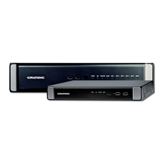
- Page 1 Owner's Manual Digital Recording Systems GRI-K1104A 4-Ch Full HD Standalone H.264 NVR GRI-K2208A 8-Ch Full HD Standalone H.264 NVR GRI-K4416A 16-Ch Full HD Standalone H.264 NVR GRI-K4416A.81.1.14.12.2012 © ASP AG...
-
Page 3: Table Of Contents
1. Introduction Thank you for purchasing a GRUNDIG digital network video recorder. This manual is for GRI-K1104A, GRI-K2208A and GRI-K4416A. Before product installation and operation, please become thoroughly familiar with this user manual and other manuals referenced by this manual. -
Page 4: Key Features Of Your Nvr
- Malfunctions due to negligence by the user - Deliberate disassembly and replacement by the user - Connection of a power source other than a properly rated power source - Malfunctions caused by natural disasters (fire, flood, tidal wave, etc.) - Replacement of expendable parts (HDD, FAN, etc.) - Malfunction caused by using an unrecommended HDD - Malfunction due to HDD failure and not due to a problem in the NVR... -
Page 5: Important Safety Instructions
- 1080p Full HD GUI 2. Important Safety Instructions GRUNDIG shall not have any responsibility for any accident or damage that may incur during the use of this product. For your safety, we provide a few instructions about installation, manipulation, cleaning, assembly/disassembly of the product as below. -
Page 6: Package Contents
3. Package Contents These parts are included: English... -
Page 7: Installation
4. Installation 4.1. Connections and Control Keys Front View: Rear View of the recorder model GRI-K1104A: Rear View of the recorder model GRI-K2208A: English... - Page 8 Rear View of the recorder model GRI-K4416A: English...
- Page 9 Remote Control: The remote control will only be active if the remote control ID matches with that specified on the NVR. If multiple NVRs are installed on one place and you have just a single remote control, use the ID button to set the remote control ID.
-
Page 10: Hdd Specifications & Replacement
The users can replace the hard disk if the existing one reaches its full capacity or becomes problematic. HDD Replacement Procedure for GRI-K1104A and GRI-K2208A: 1. At the bottom of the NVR are two metal compartments that are slide-in brackets for the HDDs. They are screwed with one screw each to the NVR main unit (there are also 4 screws, two on each side of the bracket that hold the HDD in place). - Page 11 3. Hold the middle of the HDD bracket's handle with the index finger and pull it forward while sustaining the bracket handle with your thumb and middle finger as shown in the illustration below. 4. Once the HDD bracket is separated from the main unit, remove the 4 screws on both ends of the HDD bracket to separate the HDD from the bracket.
-
Page 12: Basic Layout
4.4. Connecting To An External Device 4.4.1. Connecting the Monitor For GRI-K1104A and GRI-K2208A: This product supports only monitor models featuring 1080p 60Hz HDMI or DVI inputs. Connect the HDMI cable with the HDMI output port in the bottom rear panel and the HDMI port of the monitor, or use the HDMI-to-DVI cable to connect the NVR with the DVI port of the monitor. - Page 13 - Make sure the power connector and the cable are connected tightly and are not loose. Power connection for GRI-K1104A and GRI-K2208A: Two adaptors are provided: one for NVR operation (DC 12V), and the other for PoE (Power Over Ethernet, 48V).
- Page 14 4.4.3. Connecting the Camera Guidelines for this connection: - If the IP camera provides the Alarm I/O port or Audio I/O port, you can make the alarm or audio connection. For more details, please refer to the user manual of the IP camera. - The Ethernet connection is effective within 100 meters in distance.
- Page 15 Additional camera connection for GRI-K4416A: Connect IP cameras to the [CAM9] ~ [CAM16] ports of the hub, and connect the [LAN (DOWNLINK)] port and the hub’s [NVR] port with an Ethernet cable to establish the connections for the channels/cameras 9~16. If the distance between the NVR and IP camera is more than 100m: You may extend the transfer range by connecting a switching hub or PoE device between the Ethernet port of the NVR and of the IP camera if the desired transfer distance is longer than 100m.
- Page 16 4.4.4. Alarm I/O Connection Alarm Connection for GRI-K1104A and GRI-K2208A: Connecting the alarm input signal : Connect the signal line of an alarm input device such as a sensor to the rear [ALARM IN] port. 1. While pressing and holding the [A1] or [A2] port button in the rear bottom of the NVR, insert the alarm signal cable into the hole under the button.
- Page 17 4. To ensure secure connection, tighten the screw and pull out the wire to check if it's not pulled out. To remove the wire, loosen the screw and pull it out. 5. Install the wire-connected terminal block in the rear port. 4.4.5. Communication Ports Communication Ports of GRI-K1104A and GRI-K2208A: Communication Ports of GRI-K4416A: English...
- Page 18 RS-485 Connection : Connect the keyboard controller. You can connect a text-in device such as POS or ATM. After connecting the control device, be sure to match the connection settings between the NVR and the device. Make the communication settings in the submenu <Control Device> (See chapter 6.7.4. Control Device). 1.
- Page 19 4.4.9. Network Connection PC connection in the local network : You can connect an NVR to a PC in the same network and control or edit it on the PC monitor. 1. Connect the [WAN(UPLINK)] port in the rear panel of the NVR to the router or hub. 2.
- Page 20 PC connection from a remote network : You can connect an NVR to a PC or mobile device in the same remote network and control or edit it on the monitor of the PC or mobile device. 1. Connect the [WAN(UPLINK)] port in the rear panel to the router. 2.
-
Page 21: Monitoring
5.1. Start 1. For GRI-K1104A and GRI-K2208A: Connect the adapter to the 48V PoE power input port in the rear panel of the NVR. Connect the adaptor to the 12V power input port in the rear panel of the NVR. -
Page 22: Logout
5.3. Logout To prevent unauthorised access, it is recommended to log out when you leave the screen. Hover the cursor near the bottom of the screen to display the menu. 1. In the monitoring screen, click <MENU> in the bottom left corner of the screen and then click on <LOG OUT> to log out, or press the [LOGOUT] button on the remote control. -
Page 23: System Shutdown
5.4. System Shutdown 1. In the monitoring screen, click <Menu> in the bottom left corner of the screen to <SHUTDOWN> the system, or press the [POWER] button on the remote control. 2. Use the virtual keyboard to enter the password. 3. - Page 24 English...
- Page 25 5.5.1. Video Window Icons used in the video window : 5.5.2. Quick Menu English...
- Page 26 5.5.3. Status Bar Press the [▼] button on the remote control, or place the mouse cursor in the lower area of the screen to display the status bar. 5.5.4. Timeline Press the [▶] button on the remote control or move the mouse cursor to the right of the screen to display the timeline.
- Page 27 Click a desired split mode from 1, 4, 9, 16, 6 and 8 split screen. Or press the [DISPLAY] button on the remote control until a desired split mode is displayed. NOTE: The 4CH NVR model GRI-K1104A only supports 1- and 4-split screen modes. The 8CH NVR model GRI- K2208A only supports 1-, 4-, 9-, 6- and 8-split screen modes.
- Page 28 Pan/Tilt Control : Use the mouse to rotate the PTZ camera in the directions Up/Down/Left/Right and Diagonal. You can control the Pan/Tilt with the [▲▼◄►] buttons of the remote control. Zoom / Focus Control : You can adjust the PTZ camera's zoom and focus. Click on the <ONE PUSH FOCUS> button to adjust the camera’s focus automatically.
- Page 29 > CH : Selects the PTZ camera connected to the NVR. > PRESET (No. / Name) : You can select the preset number and name. NOTE: Up to 255 presets can be selected for a PTZ camera, while up to 16 presets can be registered to one NVR. 2.
- Page 30 3. Select a user-defined preset and register it. > DWELL : Sets the dwell time of 00 seconds before moving to the next preset location. NOTE: The <SCAN> function patrols between two preset positions at the specified speed and interval for back- and-forth monitoring.
- Page 31 Digital Zooming : You can enlarge the monitoring screen for a better view. Zooming will enlarge the video of the selected channel. If no channel is selected, channel 1 will be zoomed in. 1. Click on <Zoom> in the status bar or move the cursor to a desired channel and right-click on it to display the context menu.
- Page 32 How to check the event log : You can check the log of the events that occurred. 1. Click on the <Log> symbol (please refer to the picture) to display the “EVENT LOG” window. The log list is sorted with the latest one on top. 2.
- Page 33 How to select an audio output channel : You can select a camera outputting the voice signal from the microphone that is connected to the NVR. How to check the alarm status : You can check here the alarm status of each camera. Click on <OK> to close the window. How to check the network status : You can check here the network connection status.
- Page 34 How to check the disk status : You can check here the storage space of the current disk and you can check also if there is any problem with the disk. Click on <OK> to close the window. NOTE: For more information, please refer to Chapter 6.8.1. Disk Information). Saving captured snapshots : You can capture the current video screen and save or export to a connected storage device.
- Page 35 2. Connect a storage device, and click on the <EXPORT> button. To save the captured image onto the built-in HDD, press the <RESERVE> button. NOTE: The saved image can be found under “Archiving > Reserved data management” and can then be backed up. 3.
-
Page 36: System Setting
6. System Setting Please note that the OSD pictures shown in this manual refer mainly to the 8-channel NVR with the model name GRI-K2208A, therefore 8 frames/channels are mostly shown in the pictures. 6.1. Moving To The System Setup > How to use the mouse : >... - Page 37 6.2.1. Camera Title You can change the camera ID that is displayed on the screen like explained in the following: 1. From <SYSTEM SETUP> - <CAMERA>, select <CAMERA TITLE>. 2. Use the [▲▼◀▶/ENTER] buttons on the remote control or use the mouse to select a channel that you want to rename.
- Page 38 6.2.2. Camera Setup Adjust the Image & Exposure settings for each camera according to your preference. 1. From <SYSTEM SETUP> - <CAMERA>, select <CAMERA SETUP>. 2. Use the [▲▼◀▶/ENTER] buttons on the remote control or use the mouse to set each option of the Image menu. ATTENTION: The camera setting items may differ depending on the camera model.
- Page 39 3. Click on <EXPOSURE> tab and configure the Exposure settings in detail for each camera as necessary. ATTENTION: The exposure setting items may differ depending on the camera model. 4. To apply the change, click <APPLY> in the bottom of the screen. EXPOSURE: - MODE: Select between manual and automatic configuration for the exposure settings.
- Page 40 DIRECT ACCESS: In the direct configure tab you can activate the port forwarding of a dedicated camera. This will allow you to access the camera webinterface through the IP address of the NVR. Click on the <START> button to activate the direct configure mode. To access the camera enter the IP address + the Webservice port of the NVR into your browser and enter the correct login data.
- Page 41 6.2.3. Covert Setup You can set to hide the camera video so that a specific user or user group cannot view it. Set one or more channels that you want to hide from a specific user or user group. 1. From <SYSTEM SETUP> - <CAMERA>, select <COVERT SETUP>. 2.
- Page 42 6.2.4. Motion Sensor Set the motion sensor of the camera so that the NVR can detect a motion event. 1. From <SYSTEM SETUP> - <CAMERA>, select <MOTION SENSOR>. 2. Use the [▲▼◀▶/ENTER] buttons on the remote control or use the mouse to specify the use of each option item. >...
- Page 43 1. Click on <AREA SETUP> to move to the motion area setup screen. 2. If using the remote control, press the [ENTER] button to mark the current position. 3. Use the arrow buttons to move to a desired block and then press [ENTER]. The area setup will begin. Then, use the arrow buttons to specify the area.
-
Page 44: Display Setting
- DAYTIME : Specify the time period that will be considered as daytime. - SENSITIVITY : Set the sensitivity level of the motion sensor to either Daytime or Nighttime: 1(Low) ~ 10(High) - The higher the number is, the higher the sensitivity level becomes. - Page 45 1. From <SYSTEM SETUP> - <DISPLAY>, select <OSD>. 2. Use the [▲▼◀▶/ENTER] buttons on the remote control or use the mouse to set each option of the OSD item. > CAMERA TITLE : Specify the display of the camera title on the screen. >...
- Page 46 1. From <SYSTEM SETUP> - <DISPLAY>, select <MONITOR>. 2. Use the [▲▼◀▶/ENTER] buttons on the remote control or use the mouse to set a sequence interval for auto mode, from 1 to 60 seconds. 3. To apply the change, click on <APPLY> in the bottom of the screen. 4.
- Page 47 3. To apply the change, click on <APPLY> in the bottom of the screen. 4. When done, press the [EXIT] button on the remote control or click on <CLOSE> in the lower screen. The confirmation message will appear and you will return to the previous menu. How to add a sequence : 1.
- Page 48 How to edit a sequence : 1. Select a sequence that you want to edit from the list. 2. The "EDIT" dialogue appears. 3. Use the [▲▼◀▶/ENTER] buttons on the remote control or use the mouse to edit the selected sequence. >...
-
Page 49: Audio Setup
6.4. Audio Setup You can configure the audio and the signal beeps. 6.4.1. Audio You can configure here the default audio channel and configure the network audio transmission. 1. From <SYSTEM SETUP> - <AUDIO>, select <AUDIO>. 2. Use the [▲▼◀▶/ENTER] buttons on the remote control or use the mouse to select an item that you want to edit. >... -
Page 50: User Setting
1. From <SYSTEM SETUP> - <AUDIO>, select <BUZZER>. 2. Use the [▲▼◀▶/ENTER] buttons on the remote control or use the mouse to select an item that you want to edit. > REMOTE CONTROLLER : specify the output of a beep when you press a button on the remote control. 3. - Page 51 1. From <SYSTEM SETUP> - <USER>, select <MANAGEMENT>. 2. Use the [▲▼◀▶/ENTER] buttons on the remote control or use the mouse to add a user account or select an item that you want to edit. 3. To apply the change, click on <APPLY> in the bottom of the screen. 4.
- Page 52 3. When done, click on <OK>. The added user account will be listed. How to edit the user account information : 1. From the list of users, select a user account to edit and click <EDIT> next to it. 2. In the Edit window, make the necessary changes and click on <OK>. 3.
-
Page 53: Network Setup
> SEARCH : Set the permissions for the Search menu. > ARCHIVING : Set the permissions for the Backup menu. > SYSTEM SETUP : Set the permissions for the System Setup menu. > RECORD SETUP : Set the Access Permissions for the Record Setup menu. >... - Page 54 > IP ADDRESS : Provide the IP address. > GATEWAY : Provide the gateway address. > SUBNET MASK : Provide the subnet mask address. > 1ST DNS SERVER : Enter the address of the primary DNS server. > 2ND DNS SERVER : Enter the address of the secondary DNS server. >...
-
Page 55: English
3. To apply the change, click on <APPLY> in the bottom of the screen. 4. When done, press the [EXIT] button on the remote control or click <CLOSE> in the lower screen. The confirmation message will appear and you will return to the previous menu. 6.6.3. -
Page 56: English
Network Map : > IP ADDRESS : Indicates the internal IP address of the NVR. > MAC ADDRESS : Indicates the internal MAC address of the NVR. > DDNS ADDRESS : Indicates the internal DDNS address of the NVR. > RTSP SERVICE PORT : Indicates the network port of the video service. For remote service, the router must have set up the port forwarding. -
Page 57: System Setup
Detail Status : You can check the details of the cameras that are connected to each channel. Click on the 'Cogwheel' Button in the right area of the list to show the details. Click <RESET> in the "IP CAMERA CONFIGURATION" window to reset the IP camera. - Page 58 > DATE/TIME : Set the current time and date. Click on the 'Clock' Button to adjust the time manually. > DATE FORMAT : Specify the date format. > TIME FORMAT : Specify the time format. > TIME SERVER : Obtain the current time from the time server. Click on the 'Arrows in a Circle' Button to get the current time.
- Page 59 1. From <SYSTEM SETUP> - <SYSTEM>, select <SYSTEM MANAGEMENT>. 2. Use the [▲▼◀▶/ENTER] buttons on the remote control or use the mouse to set each option of the system management. > FW UPDATE : You can update the current software with the latest version. >...
- Page 60 - LOAD : Apply the settings of the storage device to the NVR. Connect the storage device to the USB port of the NVR. > PASSWORD : Open or close the dialogue box for the settings of the menus: quit, system settings, record settings, backup, and search.
- Page 61 How to perform the upgrade : 1. Connect the USB storage device that contains the updatable files. 2. Click on <USB>. 3. Select one or several ones from the updatable files listed in <F/W LIST>. NOTE: The Firmware should be located in the <root> directory of the USB storage device. Do not place it under a certain folder.
- Page 62 6. The progress bar displays the progress of the firmware upgrade process. 7. When the upgrade is complete, reboot the system. ATTENTION: During the updating, never turn off the NVR forcibly or disconnect the USB storage device to avoid serious damage to the product or data. If required, consult your nearest service center for professional assistance.
-
Page 63: Storage
1. From <SYSTEM SETUP> - <SYSTEM>, select <CONTROL DEVICE>. 2. Use the [▲▼◀▶/ENTER] buttons on the remote control or use the mouse to set the connection options for the control device. > SYSTEM ID : Set the ID of the NVR so that the keyboard controller can identify it. >... - Page 64 1. From <SYSTEM SETUP> - <STORAGE>, select <DISK INFORMATION>. 2. Use the [▲▼◀▶/ENTER] buttons on the remote control or use the mouse to select either <INTERNAL DISKS> or <EXTERNAL STORAGE>. Please check the status for each connected device. > START / END TIME : Shows the start time and end time of data stored in each disk. >...
- Page 65 3. When done, press the [EXIT] button on the remote control or click on <CLOSE> in the lower screen to return to the previous menu. 6.8.2. Disk Operations You can set to delete the recording automatically and set the overwrite options, and you can also format the HDD recording data.
-
Page 66: Event Setup
1. From <SYSTEM SETUP> - <STORAGE>, select <S.M.A.R.T. SETUP>. 2. Use the [▲▼◀▶/ENTER] buttons on the remote control or use the mouse to check the S.M.A.R.T. operation and specify the check interval. > S.M.A.R.T. STATUS : Read the S.M.A.R.T. information of the disk and check to display if the current disk is in normal operation. - Page 67 Alarm Out : 1. From <SYSTEM SETUP> - <EVENT>, select <ALARM OUT>. 2. Use the [▲▼◀▶/ENTER] buttons on the remote control or use the mouse to select <ALARM OUT> and configure the related settings. > NAME : You can rename the alarm. >...
- Page 68 1. Use the [▲▼◀▶/ENTER] buttons on the remote control or use the mouse to select a <DATE> for the schedule. 2. Drag the mouse to resize the cell or use the [▲▼◀▶] buttons to move to the cell, then press [ENTER]. 3.
- Page 69 1. From <SYSTEM SETUP> - <EVENT>, select <EVENT NOTIFICATION>. 2. Use the [▲▼◀▶] buttons on the remote control or use the mouse to select one option from <BUZZER>, <DISPLAY> and <EMAIL>. 3. Use the [▲▼◀▶/ENTER] buttons on the remote control or use the mouse to set the output method and duration. 4.
- Page 70 > VIDEO POP-UP : Display the video channel that is synchronised with the event on a single split screen. Set the DURATION of the single split screen. - TRANSPARENT : Keep the video pop-up displayed for as much time as the event lasts. - UNTIL KEY : Keep the video pop-up displayed until a mouse or a remote control button is pressed.
- Page 71 > ADD NEW EMAIL : If you want to add a new mail recipient beside the existing ones, click on this to add the recipient. > MINIMUM EMAIL FREQUENCY : Adjust the minimum frequency for sending the email. For example, even if you have set the minimum frequency to one minute and another event occurs in less than one minute after the last sent email, the email for the new event will be sent one minute after the previous one.
- Page 72 > NAME : You can specify the name of the alarm sensor. > OPERATION : You can specify the type of the alarm sensor. - N/O (Normal Open) : Normally the sensor is left as Open. If the sensor switches to Close, an event will be triggered.
- Page 73 > IGNORING INTERVAL : Specify the minimum interval of the motion event occurrence. For example, even if you have set the minimum frequency to 5 seconds and another motion event occurs in less than 5 seconds after the last motion event occurred, the new event will be ignored. If too many motion events occur, adjust the setting to shorten the interval.
- Page 74 1. From <SYSTEM SETUP> - <EVENT>, select <SYSTEM EVENT>. 2. Use the [▲▼◀▶] buttons on the remote control or use the mouse to specify the reaction to each event. 3. To apply the change, click on <APPLY> in the bottom of the screen. 4.
- Page 75 Record : > PANIC RECORDING : Specify the action to perform when the panic recording begins. System : > BOOTING EVENT: This event occurs when the NVR is booting. > LOGIN FAILURE: This event occurs when the NVR fails to log in. You can specify the number of failed registrations for triggering the event by clicking the ‘Arrow Down’...
- Page 76 > TEMPERATURE FAILURE : This event occurs if the internal temperature of the NVR exceeds the allowed range. Then, the NVR will not operate normally. If this is the case, check the following and take an adequate measure. - Check if the ventilation of the NVR is clogged with foreign substances. If so, remove them. - Keep the NVR away from a heat source such as a heater.
-
Page 77: Record Setting
7. Record Setting You can configure the record settings for the NVR. Only authorised users can access the Record Setup menu. 7.1. Starting the Record Setup Menu > How to use the mouse : > How to use the remote control : 7.2. - Page 78 > ALWAYS HIGH VIDEO QUALITY : Recording will proceed in the best quality regardless of the event at all times. As this option will always create recordings in the best quality, the recording period is the shortest compared to the other record modes. >...
- Page 79 > MANUAL CONFIGURATION OPTIONS : You can configure the recording settings by time, date, and channel. - SCHEDULE MODE : Set the recording schedule for a day (daily) or for a week (weekly). - PRE RECORDING TIME : Set the pre-recording time. - POST RECORDING TIME : Set the post-recording time.
- Page 80 Size/FPS/Quality Setting : 1. Please select the day of the week to perform the continuous recording. From <OPERATION MODE>, you must set the <SCHEDULE MODE> of the <MANUAL RECORD OPTION> to <WEEKLY> before you can specify the <DAY>. 2. Click a time cell from which you want to edit the SIZE/FPS/Quality and drag it to a desired cell. Or use the [▲▼◀▶] buttons on the remote control to move to the cell and press [ENTER].
- Page 81 4. When done, click on <OK>. You can check the recording size in the size table under the time selection bar. ATTENTION: The video size, FPS, quality and audio recording options may differ depending on the specification of the IP camera. For some IP cameras, the video transfer may be interrupted if some of the options are changed. Schedule Setting : 1.
- Page 82 1. From the <RECORD SETUP> menu, select <MOTION RECORD>. 2. Use the [▲▼◀▶] buttons on the remote control or use the mouse to select either <SIZE/FPS/QUALITY> or <SCHEDULE>. 3. Set each item of <RESOLUTION>, <FPS>, <QUALITY> and use of the <AUDIO> for the motion recording. NOTE: For more information, see Chapter 7.2.2.
- Page 83 1. From the <RECORD SETUP> menu, select <ALARM RECORD>. 2. Use the [▲▼◀▶] buttons on the remote control or use the mouse to either select <SIZE/FPS/QUALITY> or <SCHEDULE>. 3. Set each item of <RESOLUTION>, <FPS>, <QUALITY> and use of the <AUDIO> for the alarm recording. NOTE: For more information, see Chapter 7.2.2.
- Page 84 4. To apply the change, click on <APPLY> in the bottom of the screen. 5. When done, press the [EXIT] button on the remote control or click on <CLOSE> in the lower screen. The confirmation message will appear and you will return to the previous menu. 7.2.6.
-
Page 85: Search
8. Search You can search for the recording data in the HDD by criteria like time, thumbnail, event, etc. 8.1. Moving To The Search Menu 8.1.1. Moving to the Search menu while in monitoring > How to use the mouse : >... - Page 86 1. From the <SEARCH> menu, select <TIME SEARCH>. 2. Use the [▲▼◀▶] buttons or use the mouse to specify the search date and time from the calendar in the left corner of the screen. > FIRST : The first date of recording is automatically selected. >...
- Page 87 4. Click to move to a desired start time in the time bar, or use the buttons at the bottom of the status bar to search. > ‘Arrows in a Circle’ Button: Update the timeline. > ‘Zoom out / REW’ Button: Expand the timeline of the time bar to a greater unit of time. >...
- Page 88 1. From the <SEARCH> menu, select <THUMBNAIL SEARCH>. 2. Use the [▲▼◀▶] buttons or use the mouse to specify the search date and time from the calendar in the left corner of the thumbnail search screen. > FIRST : The first date of recording is automatically selected. >...
- Page 89 3. Double-click on a desired play time in the recording data bar, or double-click on a desired time image from the thumbnail list. You will move to the playback screen. 4. If you want to stop playing and return to the search screen, press [EXIT] or [SEARCH] on the remote control. You can also click on <MENU>...
-
Page 90: Playback
1. From the <SEARCH> menu, select <EVENT SEARCH>. 2. Use the [▲▼◀▶] buttons or use the mouse to specify the <START> and <END> times in the left of the event search list. 3. Select a channel to search. 4. Mark the checkbox of the event type to search for in the <EVENT> list. 5. - Page 91 9.1.1. Playback Screen Configuration Video Window : Displays the current video. Timeline : Displays the type of recording data. The vertical bar in the timeline indicates the current point of playback. Double-click on a desired point in the timeline to start playing the video from that point. You can also hold the left mouse button and drag it to select an area.
- Page 92 Using the Playback Bar : Bookmarking : During playback, you can add a bookmark for reserving the video data. You can view the bookmarked data in the Archive menu, which can be saved to a connected device for backup purpose. English...
-
Page 93: Archiving
1. Provide a tag in the <TAG> item for data reservation. 2. Provide the details of the reserved data in the <MEMO> input box. 3. Click on <START>. You will return to the play screen with the backup progress. 4. To stop the bookmarking, click on <BOOKMARK(‘CD Icon’)>. 5. - Page 94 1. From the <ARCHIVE> menu, select <ARCHIVE>. 2. Select a date for the archive from the calendar in the left. NOTE: The date containing recording data will be marked in a colored box. - FIRST : The first date of the recording is automatically selected. - LAST : The last date of the recording is automatically selected.
- Page 95 1. From the <ARCHIVE> menu, select <RESERVED DATA MANAGEMENT>. The reserved data will be listed. 2. Select a data type from <AVI> and <Snapshot Capture>. > AVI : Searches AVI video files stored in the DVR. > SNAPSHOT CAPTURE : Searches the captured snapshots stored in the DVR. 3.
- Page 96 3. To view the details, click on the 'Document' button next to the list. Click on <VERIFY INTEGRITY> to check if the data is corrupt or incomplete. 4. Select an item to play from the list and click <PLAY>. 5. To exit the Archive menu, click on <CLOSE>. 10.1.4.
- Page 97 4. When all information is filled in, click on <CONNECTION TEST> to check the connection status. 5. To apply the change, click on <APPLY> in the bottom of the screen. 6. When done, press the [EXIT] button on the remote control or click on <CLOSE> in the lower screen. The confirmation message will appear and you will return to the previous menu.
-
Page 98: Web Remote Viewer
11. Web Remote Viewer 11.1. What is the Web Remote Viewer? Web Remote Viewer is an application software program for a PC (for web browser) that provides a user-friendly interface for easier access and use over the network, to access the NVR remotely, to view or search live / recorded videos and to control NVR. - Page 99 > Using the URL - Check the "Network Status" and verify the <DDNS ADDRESS> and <WEB SERVICE PORT> of the NVR (Chapter 6.6.4. Network Status). - Enter the DDNS address and web service port in the address bar of the browser. Ex.: http://00115f123456.DVRLINK.NET:8080 NOTE: In a router network, you have to set the "Port Forwarding"...
-
Page 100: Live
11.2. Live 11.2.1. Live Screen At a Glance English... - Page 101 11.2.2. Switching the split mode Click on the 'Switch' button to switch the mode as follows: English...
- Page 102 11.2.3. Saving the video 1. Click on the 'Disk symbol' button to start saving. 2. The video from the selected channel will be saved to the PC in the AVI format (Default path: C:\SaveFolder). Click on the 'Disk symbol' button again to stop saving. Click on <ActiveX Setting> to display the context menu to see where you can change the saving path.
- Page 103 11.2.4. Printing 1. Click on the 'Printer symbol' button. 2. The current screen will be printed with the printer connected to the PC. 11.2.5. Screen Capture 1. Click on the 'Camera symbol' button. 2. The current screen of the selected channel will be saved to the path specified in the PC (Default path: C:\SaveFolder).
-
Page 104: Search
11.2.7. Status tab Click on <Status> at the bottom of the screen. You can check the event occurrence for each channel of the connected NVR. 11.2.8. Log tab Click on <Log> at the bottom of the screen. You can check the log of the connected NVR. 11.2.9. - Page 105 11.3.1. Search Viewer At a Glance English...
- Page 106 11.3.2. Search by time Use the timeline to search for the data recorded in the NVR. 1. Select a date that you want to search for. 2. Click on <REFRESH>. 3. Check the existence of recording data in the bottom time line and specify the time range for your search. You can specify the start time by moving the time bar.
-
Page 107: Setup
11.4. Setup Click on <SETUP> to display the remote control screen for the NVR. When done, click on <OK> to apply the changes to the remotely connected NVR. NOTE: If the NVR is in process of system or record setting, the remote control will be disabled. ATTENTION: If you change the settings remotely at will, the major 'Record Settings' of the NVR may be changed, which is not recommended at all. - Page 108 Image Setting : Adjust the brightness, contrast and more of each camera. When done, click <OK> to apply the changes. NOTE: The default colour value is <50> (Brightness, Contrast, Tint, Color). If you change the default settings, the video from the NVR or the video colour may not be displayed properly. Exposure: Adjust the exposure related settings of the camera.
- Page 109 Covert Setting : You can set to hide the video of a specific camera from a specific user. Set to hide the camera video so that a specific user or user group cannot view it. To change the covert settings from user group to user, move to the <USER>...
- Page 110 PTZ Setup: If you have a camera connected via a serial connection you can adjust the settings for the PTZ camera here. Select the camera and adjust the used address number, protocol and baudrate of the camera. Activate the RS485 button, if the camera id connected over the RS485 connection.
- Page 111 Monitor Settings : You can set the interval of an active sequence. Specify the interval and click on <OK> to apply it. 11.4.4. Audio Audio/Buzzer : You can configure the settings of the voice and audio signal. NOTE: For details about each displayed item, please refer to Chapter 6.4. Audio Setup. English...
- Page 112 11.4.5. User User Management : You can add a user account and change the password. NOTE: For details about each displayed item, please refer to Chapter 6.5. User Setting. To add a user, click on <Add> and provide the user information. If you want to delete the user, click on <DEL> next to it.
- Page 113 Group Permission Setting : You can grant different user groups different permissions to a specific menu. Mark the checkboxes of the menu items accessible by the user group. When done, click on <OK> to apply the changes. NOTE: For more information about the accessible menu items, refer to Chapter 6.5.2. Group Authority. 11.4.6.
- Page 114 DDNS Setting : You can configure the DDNS settings so that remote users who are connected to the network can access the DVR remotely. Change the DDNS settings and click on <OK> to apply the changes. Email Setting : You can register and test an email address so that an email notification is delivered at a specific interval or if an event occurs.
- Page 115 11.4.7. System Date/Time Setting : Specify the current date and time. When done, click on <OK> to apply the changes. NOTE: For more information about each item of the time and date settings, refer to Chapter 6.7.1. Date/Time. System Management : You can configure the access settings of: log in, log out, and auto logout.
- Page 116 System Information : You can check the information of the system firmware version, disk space, and network settings, as well as the status information of the network connection and alarm I/O. Control Device Setting : Set the connection of both, the remote control and the keyboard control. Change the communication settings and click on <OK>...
- Page 117 11.4.8. Storage Device Information : You can check a list of internal/external storage devices connected to the NVR as well as the recording time information of each device. S.M.A.R.T. Status : You can check the S.M.A.R.T. status for each of the internal and external devices. What is S.M.A.R.T.? It is a sort of HDD self-diagnosis tool that detects any error on the system and alerts the user if an error occurs.
- Page 118 11.4.9. Sensor Alarm Output : Specify the alarm output conditions with the work schedule. When done, click on <OK> to apply the changes. NOTE: For more information about the alarm output and ON/OFF schedule, refer to Chapter 6.9.1. Alarm Out. English...
- Page 119 Event Notification : Specify the notification method using one of <BUZZER OUT>, <DISPLAY> and <EMAIL> against an event alarm that occurs. Specify the buzzer output time, display time and email notification, and click on <OK> to apply the changes. NOTE: For more information about the event notification, refer to Chapter 6.9.2. Event Notification. English...
- Page 120 Alarm Sensor : You can configure the settings of the alarm sensor and specify the operation of the sensor if an event occurs. When done, click on <OK> to apply the changes. NOTE: For more information about each of the alarm sensor actions, refer to Chapter 6.9.3. Alarm Sensor. Motion Sensor : You can set an action to execute when a motion is detected.
- Page 121 Video Loss : You can select an action for <BUZZER> and <EMAIL> and determine what to do on the alarm output port if no video is received from the camera. When done, click on <OK> to apply the changes. System Event : You can set which action to perform if an event related to disk, recording, network or system happens.
- Page 122 11.4.10. Record Setup Record Setting : You can set the recording options for Auto or Manual mode. English...
- Page 123 When done, click on <OK> to apply the changes. NOTE: For more information about how to set each mode, refer to 7.2.1. Operation Mode. Continuous Recording : You can configure the settings of: continuous recording time, recording size, frame rate per second and quality. Click on the 'Arrow pointing to the bottom' next to each item to display the list of values available.
- Page 124 When you complete the recording size and schedule settings, click on <OK> to apply your settings. NOTE: For more information about the continuous recording size and schedule, refer to Chapter 7.2.2. Continuous Recording. Motion Recording : Set the <SIZE/FPS/QUALITY/AUDIO> and the <SCHEDULE> to apply if a motion event occurs. Click on the 'Arrow pointing to the bottom' next to each item to display the list of values available.
- Page 125 Complete the setting of <SIZE/FPS/QUALITY/AUDIO> for the motion recording as well as <SCHEDULE>, and click on <OK> to apply the changes. NOTE: For more information about the motion recording size and schedule, refer to Chapter 7.2.3. Motion Recording. Alarm Recording : Set <SIZE/FPS/QUALITY/AUDIO>...
- Page 126 Panic Recording : From the <PANIC RECORD> menu, you can set the resolution, FPS, quality and audio settings according to your preference. Click on the 'Arrow pointing to the bottom' next to each item to display the list of values available. When you have completed the manual record settings, click on <OK>...
-
Page 127: Archive Viewer
12. Archive Viewer You can playback here the data archived in the NVR. And you can playback the HDD data recorded by the NVR. 12.1. Starting the Backup Player 1. Connect the NVR to the backup USB storage device and store the backup on it. 2. - Page 128 5. Check the integrity of the archived file. 6. When done, the archived file will be played on the screen. English...
-
Page 129: Backup Player At A Glance
12.2. Backup Player At a Glance English... - Page 130 12.2.1. Video Capture Click on the 'Camera' button in the left corner at the bottom of the screen to capture the current video image. > Selected Video : Capture the actual frame of the current video. > Screen : Capture the visible portion of the current video. >...
- Page 131 12.2.3. Settings Click on the 'Rhombus' button to configure the Backup Player settings. You can check the version of the Backup Player. > Maintain the image aspect ratio : Preserve the aspect ratio of the image. If you do not mark this option, the image will be adjusted to fit the screen.
- Page 132 Specifications GRI-K1104A Operating System Embedded Linux IP Inputs 4 channels Recording Resolution max. 1920x1080 depending on the camera performance Recording Speed 100 fps Video Compression H.264 Storage Max. Expansion 17.5 TB (2x2,5 TB SATA and 5x2,5 TB eSATA) Video Outputs...
- Page 133 Specifications GRI-K4416A IP Inputs 16 channels Recording Speed 400 fps Storage Max. Expansion 25 TB (5x2,5 TB SATA and 5x2,5 TB eSATA) Video Outputs 1 VGA, 1 HDMI Display Speed 400 fps Display Mode Full screen, 4, 8, 9, 16 Audio Inputs 16 CH over IP Alarm Inputs...
-
Page 134: Ec Declaration Of Conformity
EC Declaration of Conformity GRI-K1104A 4-Ch Full HD Standalone H.264 NVR GRI-K2208A 8-Ch Full HD Standalone H.264 NVR GRI-K4416A 16-Ch Full HD Standalone H.264 NVR It is hereby certified that the products meet the standards in the following relevant provisions:... - Page 135 Open Source License Report on the Product The software included in this product contains copyrighted software that is licensed under the GPL/LGPL. 0. This License applies to any program or other work which contains a notice placed by the copyright holder saying it may be distributed under the terms of this General Public License.
- Page 136 b) Accompany it with a written offer, valid for at least three years, 9. The Free Software Foundation may publish revised and/or new versions of the General Public License from time to time. Such new versions will be similar in to give any third party, for a charge no more than your cost of spirit to the present version, but may differ in detail to address new problems or physically performing source distribution, a complete machine-...
- Page 137 The hypothetical commands `show w' and `show c' should show the appropriate Finally, every program is threatened constantly by software patents. States parts of the General Public License. Of course, the commands you use may be should not allow patents to restrict development and use of software on general- called something other than `show w' and `show c';...
- Page 138 The Corresponding Source need not include anything that users can regenerate combined with it such as to form a larger program, in or on a volume of a automatically from other parts of the Corresponding Source. storage or distribution medium, is called an “aggregate” if the compilation and its resulting copyright are not used to limit the access or legal rights of the compilation's users beyond what the individual works permit.
- Page 139 when the modification itself materially and adversely affects the operation of the this License (for any work) from that copyright holder, and you cure the violation network or violates the rules and protocols for communication across the prior to 30 days after your receipt of the notice. network.
- Page 140 then the patent license you grant is automatically extended to all recipients of TO YOU FOR DAMAGES, INCLUDING ANY GENERAL, SPECIAL, INCIDENTAL OR the covered work and works based on it. CONSEQUENTIAL DAMAGES ARISING OUT OF THE USE OR INABILITY TO USE THE PROGRAM (INCLUDING BUT NOT LIMITED TO LOSS OF DATA OR DATA BEING RENDERED INACCURATE OR LOSSES SUSTAINED BY YOU OR THIRD A patent license is “discriminatory”...
- Page 141 When a program is linked with a library, whether statically or using a shared a) The modified work must itself be a software library. library, the combination of the two is legally speaking a combined work, a b) You must cause the files modified to carry prominent notices derivative of the original library.
- Page 142 If such an object file uses only numerical parameters, data structure layouts and 9. You are not required to accept this License, since you have not signed it. accessors, and small macros and small inline functions (ten lines or less in However, nothing else grants you permission to modify or distribute the Library length), then the use of the object file is unrestricted, regardless of whether it is or its derivative works.
- Page 143 INCIDENTAL OR CONSEQUENTIAL DAMAGES ARISING OUT OF THE USE OR CONTRACT, STRICT LIABILITY, OR TORT (INCLUDING NEGLIGENCE OR INABILITY TO USE THE LIBRARY (INCLUDING BUT NOT LIMITED TO LOSS OF OTHERWISE) ARISING IN ANY WAY OUT OF THE USE OF THIS SOFTWARE, EVEN DATA OR DATA BEING RENDERED INACCURATE OR LOSSES SUSTAINED BY IF ADVISED OF THE POSSIBILITY OF SUCH DAMAGE.
Need help?
Do you have a question about the GRI-K1104A and is the answer not in the manual?
Questions and answers