
Related Manuals for Plura MVM-124


Summary of Contents for Plura MVM-124
- Page 1 ® MVM - Series Operating MVM-124 Instructions MVM-140 MVM Series Monitors MVM-146 MVM-147-16CH...
-
Page 2: Important Safety Instructions
Important Safety Instructions Please read this manual thoroughly before operating the monitor. Unplug monitor from the wall outlet before cleaning the LCD screen. Do not use liquid cleaners or aerosol cleaners. Use ONLY a damp cloth provided. Don’t use any unauthorized accessories not recommended by the manufacturer as they may cause hazards. -
Page 3: Fcc Notice
FCC Notice This device complies with Part 15 of FCC Rules. Operation is subject to the following two conditions: (1)This device may not cause harmful interference, and (2) this device must accept any interference received, including interference that may cause undesired operation. To assure continued compliance, follow the attached installation instruction and do not make any unauthorized modifications. -
Page 4: Safety Precautions
Safety Precautions WARNING: CAUTION TO REDUCE THE RISK OF FIRE OR SHOCK HAZARD, DO NOT EXPOSE THIS EQUIPMENT TO RAIN OR MOISTURE. RISK OF ELECTRICAL SHOCK TO REDUCE THE RISK OF FIRE OR SHOCK HAZARD, DO NOT OPEN KEEP THIS EQUIPMENT AWAY FROM ALL LIQUIDS. USE AND STORE ONLY IN LOCATIONS WHICH ARE NOT EXPOSED TO THE RISK OF DRIPPING OR SPLASHING CAUTION: TO REDUCE THE ELECTRICK SHOCK. - Page 5 Safety Precautions continued Caution for AC Power Cord FOR YOUR SAFETY PLEASE READ THE FOLLOWING TEXT CAREFULLY. Appropriate AC Power Cord must be used in each local area. FOR CONTINENTAL EUROPE, ETC FOR U.K. ONLY Not for use in the U.K. If the plug supplied is not suitable for your socket outlet, it should be cut off and appropriate one fitted.
-
Page 6: Operation
Safety Precautions continued Important Safety Warnings Power Operate unit only on the specified supply voltage. Disconnect power cord by connector only. Do not pull on cable portion. Do not place or drop heavy or sharp-edged objects on power cord. A damaged cord can cause fire or electrical shock hazards. -
Page 7: Upon Receipt
Upon Receipt Unpacking MVM units and their accessories are fully inspected and adjusted prior to shipment. Operation can be performed immediately upon completing all required connections and operational settings. Check your received items against the packing lists below. ITEM REMARKS AC Cord 1 set One AC cord, and one AC cord retaining clip... - Page 8 Contents MVM ......................9 1. Prior to Starting ......................9 1-1. Welcome......................9 1-2. About MVM ......................9...
-
Page 9: Prior To Starting
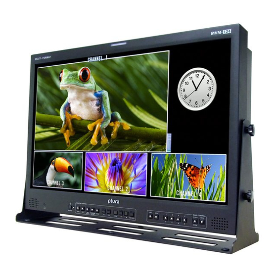
PLURA BROADCAST provides a wide range of products, from basic support units to complex monitoring systems, which have been increasingly joined by products for computer video based systems. Whatever your needs, talk to your PLURA BROADCAST representative. We will do our best to be of continuing service to you. 1-2. About MVM The MVM Multi Viewer is a four split-screen multi viewer that accepts four inputs (of HD-SDI, SD-SDI, and Analog Composite signals), resizes the images and display on a single screen. -
Page 10: Quick Start
2. Quick Start This chapter describes the basic operations to set up the system for your MVM multi viewer. Refer to the section given for each operation you may need more details, if necessary. 2-1. Connection Connect the MVM to an AC power source using the supplied accessory cord. Connect the signal source device(s) to the left connector(s) of each set of 1 to 4 HD-SDI/SD-SDI/COMPOSITE INPUT connectors to supply input signal(s). -
Page 11: Pc Network Settings
2. Quick Start continued 2-2. Displaying Image on MVM-1XX Monitor Checking Monitor Display of Output Image Turn on the power switch on the MVM front panel. When power switch is turned on, the image is displayed on the MVM-1XX monitor. Is the image displayed on the monitor? Follow the steps given for each case The output screen size is set to 1920 x 1200 in 60Hz at the factory. - Page 12 2. Quick Start continued 2-3-2. Installing MVM Layout Editor Install the MVM Layout Editor on the PC using the supplied CD-ROM. In this section a rough instruction for the installation is given. For more details see section 16-4. “Installing MVM Layout Editor” in the part 3, MVM Layout Editor of this manual.
- Page 13 2. Quick Start continued 2-3-3. Starting MVM Layout Editor To start MVM Layout Editor, go to Start > Programs > PLURA and select “MVM Layout Editor”. After the application is started the screen shown below is displayed. MVM ID Box Enter the IP address, ID and password of the MVM that you wish to connect in the MVM ID boxes at the top- right of the main screen.
-
Page 14: Panel Descriptions
3. Panel Descriptions 3-1. Front Panel POWER1 switch Used to turn the power unit 1 On/Off. Pressing “ ” side turns power on. FULL (Full screen display button) Used to set the display in full screen mode. SPLIT (Split screen display button) Used to set the display in split screen mode. -
Page 15: Rear Panel
3. Panel Descriptions continued 3-2. Rear Panel HD-SDI/SD-SDI/COMPOSITE INPUT 1 - 4 Used to input HD/SD-SDI or analog composite signals (Automatic recognision supported) The respective right connectors are active through output connectors to output signals from left connectors to monitors. •... - Page 16 4. Connection 4-1. System directly with PC IMPORTANT: To directly connect PC and MVM, use a crossover LAN cable for the connection. To connect PC and MVM using a hub or such device, use a straight LAN cable. 4-2. System with Video Transmission...
-
Page 17: Network Mode
4. Connection continued 4-2-1. Network Mode The system with video transmission has two different network modes such as ‘Unicast mode’ and ‘Multicast mode’. For the mode settings, see section 7-2. “SYSTEM” and 7-3. “LAN”. 4-2-1-1. UNICAST Mode The UNICAST mode using TCP/IP protocol supports the system that can provide video output to one monitor by MVM Live Viewer. - Page 18 5. Operations 5-1. Operation at Startup After the power is turned on, operation resumes from the last screen before the power was turned off. If a menu screen was displayed when the unit was turned off, operation resumes from the status before the menu screen. 5-2.
- Page 19 5. Operations continued 5-5. REMOTE/TALLY MVM can be remotely controlled using contact inputs to the TALLY IN/REMOTE connector on the rear panel. The connector is also provided with pins for external tally inputs that enable to display two color borders on video frames. Connector pin assignments (25-pin, D-sub female) Inch screws Pin no.
- Page 20 5. Operations continued 5-5. REMOTE/TALLY continued Input Connector The figure at right depicts the MVM circuit for each input pin. Output Connector The figure at right depicts the MVM circuit for each output pin. Outputs 5V TTL level alarm signal. 5-5-1.
-
Page 21: Screen Display
6. Screen Display 6-1. Full Screen The display mode can be selected from three options. See section 18-2-1. “System” in the part 3, MVM Layout Editor of this manual for details on setting display mode. MODE1 Displays the title and audio level meters without overlapping on the video image. -
Page 22: Split Screen
6. Screen Display continued 6-2. Split Screen The split screen layout can be freely arranged using the supplied Layout Editor. Image Display Window Windows to display each channel input. Display mode within the windows varies depending on the settings of display mode. - Page 23 6. Screen Display continued 6-3. Crop The effective pixel area (where picture exists) of the input display can be set. The black area produced by converting images to 4:3 or 16:9 can be reduced or eliminated, and the images can be enlarged and displayed to best fit the output screen.
-
Page 24: Audio Level Meter
6. Screen Display continued 6-4. Audio Level Meter Audio level meter for up to 8 channels can be displayed for each HD-SDI and SD-SDI input. For the details on audio level meter settings, see section 19-3-8. “Changing Display Position of Audio Level Meters” in the part 3, MVM Layout Editor of this manual. -
Page 25: Menu Operations
7. Menu Operations Submenus can be accessed from the main menu for completing various settings. 7-1. Main Menu Screen Press and hold down the MENU button for at least two seconds to display the MAIN MENU. MAIN MENU 1 SYSTEM 2 LAN 3 SERIAL 4 VERSION... - Page 26 7. Menu Operations continued Menu Diagram...
- Page 27 7. Menu Operations continued 7-1. Main Menu Screen On the MAIN MENU, move the cursor to [SYSTEM] and press the ENTER button. The SYSTEM screen is displayed as shown below. SYSTEM INPUT FORMAT AUTO NETWORK MODE UNICAST ROOT PASSWORD 00000 ADJUST 1/MINUTE TIME STANDARD...
-
Page 28: Main Menu Screen
7. Menu Operations continued 7-1. Main Menu Screen On the SYSTEM screen, move the cursor to [INPUT FORMAT] and press the ENTER button. The INPUT FORMAT screen is displayed as shown below. On the INPUT FORMAT screen, formats of input signals can be seen and set. INPUT FORMAT 1080/59.94i 720/59.94p... - Page 29 7. Menu Operations continued 7-3. LAN On the MAIN MENU screen, move the cursor to [LAN] and press the ENTER button. The LAN screen is displayed as shown below. On the LAN screen network setting can be seen and changed. IP ADDRESS 192.168.0.1 MASK LENGTH...
- Page 30 7. Menu Operations continued 7-4. SERIAL On the MAIN MENU screen, move the cursor to [SERIAL] and press the ENTER button. The SERIAL screen is displayed as shown below. SERIAL SERIAL SELECT RS-232C BAUDRATE 9600 PARITY NONE SERIAL ID Operating Procedure Button Action Moves the cursor up.
- Page 31 7. Menu Operations continued 7-5. VERSION On the MAIN MENU screen, move the cursor to [VERSION] and press the ENTER button. The VERSION screen is displayed as shown below. On the VERSION screen, the version information of MVM can be seen. VERSION SOFT 01.00...
- Page 32 8. Output Size Test Mode This mode is used to verify that the connected monitor can display the output image in the format set on the MVM. Turn the power on while pressing the LOCK button, the screen shown below will be displayed in the format used last time the power was turn off.
- Page 33 9. RS-232C/422/485 Interface The factory default is set to RS-232C interface. To change the interface from RS-232C to RS-422 or RS-485, or to change the termination ON/OFF setting, change the settings at [SERIAL SELECT] in the SERIAL menu and the jumper switches in the main unit.
- Page 34 9. RS-232C/422/485 Interface continued 9-2. RS-232C/422/485 Connector RS-232C connector pin assignment (9-pin, D-sub male) Pin no. Signal In/Out Description Unassigned Output Transmit data Input Receive data Input Data set ready Signal ground Output Data terminal ready Input Clear to send Output Request to send Unassigned...
- Page 35 9. RS-232C/422/485 Interface continued Serial communication standard Transmission mode Asynchronous, Full-duplex (RS-232C, RS-422), Half-duplex (RS-485) Baud rate Select from 9600, 19200, or 38400[bps] Data length 8 [bit] Stop bit 1 [bit] Parity Select from NONE, ODD, or EVEN Flow control None IMPORTANT: DSR/DTR and RTS/CTS are looped back in the MVM.
-
Page 36: Troubleshooting
10. Troubleshooting 9-2. RS-232C/422/485 Connector If any of the following problems occur during operation of the MVM, before assuming a unit malfunction has occurred, follow the troubleshooting procedures below to see if the problem can be corrected. IMPORTANT: If the problem is not corrected by performing the procedures below, turn the unit off and then on again. -
Page 37: Specifications And Dimensions
11. Specifications and Dimensions 11-1. Specifications 1080/60i, 1080/59.94i, 1080/50i, 720/60p, 720/59.94p, 720/50p TV Standard 525/60 (NTSC), 625/50 (PAL) 4 inputs of any inputs below (Mix input, asynchronous acceptable) HD-SDI: 1.485Gbps or 1.485/1.001Gbps 75Ω BNC Video Input SD-SDI: 270Mbps 75Ω BNC Analog composite: 1.0V(p-p) 75Ω... - Page 38 11. Specifications and Dimensions continued 11-1. Specifications RS-232C/RS-422/RS-485: 9-pin D-sub male, 1 port 9,600/19, 200/38, 400bps, data length 8bit, stop bit 1bit, parity NONE/ODD/ Baud rate: EVEN 25-pin D-sub female *Shared use with REMOTE IN TALLY IN: 4 inputs x 2colors (red or green border display) TTL negative logic pulse level or Make contact Interfaces 25-pin D-sub female *Shared use with TALLY IN...
- Page 39 11. Specifications and Dimensions continued 11-1. Specifications...
-
Page 41: Lan Command
RS-232C/422/485/ LAN COMMAND Version 2.0 - Higher... -
Page 42: Communication Setting
12. Communication Setting 12-1. RS-232C / 422 / 485 Interface Communication Standards The communication standards when connecting the unit to a serial controller via RS-232C, RS-422 or RS-485 are as follows. Transmission speed 9600bps, 19200bps or 38400bps Data length 8 [bit] Stop bit 1 [bit] Parity... - Page 43 12. Communication Setting continued 12-3. Notes on the LAN Interface IP address, Subnet mask, Gateway and Port number settings must be set to suit your network system. Consult your system administrator before setting IP address, Subnet mask, Gateway and Port number to avoid troubles, if configuring the system in an existing LAN.
- Page 44 13. Command Protocol Format All command contents are transmitted and received in ASCII code. Follow each format to make and send message commands. The command formats are as shown in the following pages. 13-1. Commands Formats for RS-232C, RS-422 and LAN (without Password) Command Format Command code + Command parameter + CR + LF (3 byte)
-
Page 45: Command Format
13. Command Protocol Format continued 13-2. Commands Formats for RS-485 The ID header is located in front of the Command code. The ID number specifies the ID of MVM (00-31) to be controlled. The ID number is set in the menu of MVM. Command Format I + ID number + Command code + Command parameter + CR + LF (2 byte) - Page 46 13. Command Protocol Format continued All command contents are transmitted and received in ASCII code. Follow each format to make and send message commands. The command formats are as shown in the following pages. 13-3. Commands Formats for LAN (with Password) Command Format ID number + Password + Command code + Command parameter + CR + LF (n byte)
-
Page 47: Response Message Format
13. Command Protocol Format continued 13-4. Response Message Format Normal end Messages in the following format are returned after normal reception and processing. Byte Parameter Command Description Message code "OK" End code Abnormal end If something prevents commands from being issued normally, messages in the following format are returned. Byte Parameter Command... -
Page 48: Control Commands
14. Control Commands 14-1. Full Screen Display Displays the specified channel in full screen. With normal reception and processing, the response message is “OK.” “ERR004” message is returned during MENU screen display. Byte Parameter Command Description Command code Reserve Fixed to "0" Input channel 01-04 Channel no. - Page 49 14. Control Commands Format continued 14-4. JPEG Compression Setting for Transmission Sets a JPEG compression ratio for video transmission. With normal reception and processing, the response message is “OK.” Byte Parameter Command Description Command code Low quality Normal quality JPEG compression ratio Fine quality Superfine quality End code...
-
Page 50: Display Mode Setting
14. Control Commands 14-6. Display Mode Setting Selects a display mode. With normal reception and processing, the response message is “OK.” “ERR004” message is returned during MENU screen display. Byte Parameter Command Description Command code Reserve Fixed to "00" Mode1 Display mode Mode2 Mode3... - Page 51 14. Control Commands Format continued 14-8. Screen Layout Setting Defines each screen layout (Layout1-4). With normal reception and processing, the response message is “OK.” “ERR004” message is returned during MENU screen display. Byte Parameter Command Description Command code Reserve Fixed to "0" Layout screen 01-04 Layout no.
-
Page 52: Save Layout
14. Control Commands Format continued 14-9. Crop Area Setting Specifies the area and size to crop images. With normal reception and processing, the response message is “OK.” “ERR004” message is returned during MENU screen display. Byte Parameter Command Description Command code Displayed channel 01-04 Crop area size (Top) - Page 53 14. Control Commands Format continued 14-12. Audio Level Meter Display Function Setting Sets display functions in audio level meter. With normal reception and processing, the response message is “OK.” “ERR004” message is returned during MENU screen display. Byte Parameter Command Description Command code Reference level...
- Page 54 14. Control Commands Format continued 14-14. Border Setting Specifies the border settings for each channel. With normal reception and processing, the response message is “OK.” “ERR004” message is returned during MENU screen display. Byte Parameter Command Description Command code Reserve Fixed to "0"...
- Page 55 14. Control Commands Format continued 14-16. Tally Display Setting Specifies the settings for tally display. With normal reception and processing, the response message is “OK.” “ERR004” message is returned during MENU screen display. Byte Parameter Command Description Command code Reserve Fixed to "00"...
- Page 56 14. Control Commands Format continued 14-19. Video Loss Reset Performs alarm reset for video loss. With normal reception and processing, the response message is “OK.” “ERR004” message is returned during MENU screen display. Byte Parameter Command Description Command code End code 14-20.
-
Page 57: Status Request Commands
15. Status Request Commands 15-1. Version Requests the software version and hardware version of the MVM. Returns a message as shown below after normal reception and processing. [RVS] Status Request Command Byte Parameter Command Description Command code End code [AVS] Status Request Response Messages Byte Parameter Message... - Page 58 15. Status Request Commands continued 15-3. Output Screen Status Requests the current status of “Output channel.” Returns a message as shown below after normal reception and processing. [RDP] Status Request Command Byte Parameter Command Description Command code Reserve Fixed to "0" End code [ADP] Status Request Response Message Byte...
- Page 59 15. Status Request Commands continued 15-5. Video Transmission Information Requests the current status of “Video transmission.” Returns a message as shown below after normal reception and processing. [RNR] Status Request Command Byte Parameter Command Description Command code End code [ANR] Status Request Response Message Byte Parameter Message...
- Page 60 15. Status Request Commands continued 15-7. Display Mode Requests the setting status of display mode. Returns a message as shown below after normal reception and processing. [RAM] Status Request Command Byte Parameter Command Description Command code Reserve Fixed to "00" End code [AAM] Status Request Response Message Byte...
- Page 61 15. Status Request Commands continued 15-9. Layout Screen Information Requests the information of each layout screen. Returns a message as shown below after normal reception and processing. [RLD] Status Request Command Byte Parameter Command Description Command code Reserve Fixed to "0" Target screen 01-04 Layout no.
- Page 62 15. Status Request Commands continued 15-10. Crop Area Setting Requests the setting status of “Crop area”. Returns a message as shown below after normal reception and processing. [RRG] Status Request Command Byte Parameter Command Description Command code Target channel 01-04 Channel no.
- Page 63 15. Status Request Commands continued [AAC] Status Request Response Message Byte Parameter Message Description Message code Reserve Full screen Target screen 01-04 Layout no. 1-4 Target channel 01-04 Channel no. 1-4 Level meter display Number of channels to be displayed 11-15 Reserve End code...
- Page 64 15. Status Request Commands continued 15-13. Title Information Requests the title information for each channel. Returns a message as shown below after normal reception and processing. [RTT] Status Request Command Byte Parameter Command Description Command code Reserve Fixed to "0" Full screen Target screen 01-04...
- Page 65 15. Status Request Commands continued 15-14. Border Information Requests the border information for each layout screen. Returns a message as shown below after normal reception and processing. [RBD] Status Request Command Byte Parameter Command Description Command code Reserve Fixed to "0" Target screen 01-04 Layout no.
- Page 66 15. Status Request Commands continued 15-15. Full Screen Information Requests the setting status of “Output resolution” and “Display mode” for full screen. Returns a message as shown below after normal reception and processing. [RFL] Status Request Command Byte Parameter Command Description Command code Reserve...
- Page 67 15. Status Request Commands continued 15-17.Video Loss ON/OFF Requests the setting status of “Video loss detection.” Returns a message as shown below after normal reception and processing. [RBD] Status Request Command Byte Parameter Command Description Command code Target channel 01-04 Channel no.
- Page 68 15. Status Request Commands continued 15-19. Reference Clock Selection Requests the setting status of “Reference Clock” for the clock display. Returns a message as shown below after normal reception and processing. [RDC] Status Request Command Byte Parameter Command Description Command code End code [AFL] Status Request Response Message Byte...
- Page 69 15. Status Request Commands continued 15-21. Internal Clock Time Requests the current internal clock time. Returns a message as shown below after normal reception and processing. [RDT] Status Request Command Byte Parameter Command Description Command code End code [ADT] Status Request Response Message Byte Parameter Message...
- Page 71 MVM Layout Editor Version 2.0...
-
Page 72: System Requirements
16. Setup 16-1. Overview MVM Layout Editor is a software to customize the layout of the MVM split screen from a computer. Up to 4 preset patterns (SPLIT 1 to 4) can be stored. Those stored layouts are easily recalled by using the SPLIT button on the front panel of MVM. - Page 73 16. Setup continued 16-4. Installing MVM Layout Editor Load the supplied Installation CD-ROM into the PC, and open the CD-ROM drive. Run the file “setup. exe” to start the setup wizard. If [.NET Framework 2.0] is not installed on your PC, the screen shown below is displayed. Click Accept. If [.NET Framework 2.0] is already installed on your PC, this screen is not displayed.
- Page 74 16. Setup If [.NET Framework 2.0] is not installed, the installation starts. When installation of [.NET Framework 2.0] is complete, the screen shown below is displayed requiring a reboot. Click Yes to reboot your PC. After the setup wizard is started, click Next.
- Page 75 16. Setup continued Select the installation directory. It is not necessary to change the folder. Select whether to install MVM Layout Editor for current user only or for all users. The default is set to the current user. When the settings are completed, click NEXT>.
- Page 76 16. Setup When installation is completed normally, the screen shown below is displayed. Click Close to quit the setup wizard. 16-5. Removing MVM Layout Editor To remove MVM Layout Editor, follow the procedure below. Go to Start > Control Panel. In the Add or Remove Programs window, select “MVM Layout Editor”, and click Remove.
-
Page 77: Communication Standard
16. Setup continued 16-6. Connections To use MVM Layout Editor, connect MVM and PC over a LAN interface. Be aware that the cables and equipment used vary depending on the connection method. Use a crossover LAN cable to connect the computer directly to the MVM. - Page 78 17. Starting & Exiting MVM Layout Editor 17-1. Starting MVM Layout Editor To start MVM Layout Editor, go to Start > Programs > PLURA and select “MVM Layout Editor”. 17-2. Exiting MVM Layout Editor To exit MVM Layout Editor, click the x button at the top-right corner of the screen.
-
Page 79: Main Screen
18. Main Screen and Dialog Boxes 18-1. Main Screen After the application is started the screen shown below is displayed. File Buttons Layout Upload Buttons MVM ID Boxes Setting Buttons 18-1-1. MVM ID Boxes IP address Enter the IP address of MVM to be connected. Enter the ID specified in MVM. -
Page 80: Setting Buttons
18. Main Screen and Dialog Boxes continued 18-1-3. Layout Upload Buttons Layout Number Selects a layout number of the layout to be edited or saved. Up to 4 patterns can be saved to MVM. Once the layout number is selected, the layout is loaded from MVM into the layout editing area. NOTE: Selecting the same number as the layout number of MVM allows users to easily check the layout, since the changes in the layout editing area are applied to MVM in real-time. -
Page 81: Output Resolution
18. Main Screen and Dialog Boxes continued 18-1-5. Layout editing area and Editing Tools Layout editing area base point The coordinate (0, 0) base point of the layout editing area is the top-left corner of the area. The X coordinate value increases from left to right. -
Page 82: Aspect Ratio
18. Main Screen and Dialog Boxes continued Window Size (W, H) Displays the size of the selected window. Also the window size can be adjusted by changing the numeric values. If Aspect Ratio is set to other than Free, changing either of W (width) or H (height) changes the other automatically. - Page 83 18. Main Screen and Dialog Boxes continued Add / Move 1/16 size window Clicking any one of the add 1/16 size window icon at the right of the layout editing area adds a 1/16 size window at the place each icon depicts. Every click add a window in a row shown in the icon.
- Page 84 18. Main Screen and Dialog Boxes continued Audio Level Meter (CH1-CH4) Display Position (X, Y) Display order of Audio Level Meter (CH1-CH4) Displays the display positions of the audio level meters (CH1-CH4) of the selected window. Also the audio level meter display position can be adjusted by changing the numeric value. The X value represents the position of the left edge of audio level meter and the Y value represents the bottom edge of audio level meter.
-
Page 85: System Setting
18. Main Screen and Dialog Boxes continued 18-2. System Setting Clicking the System Setting button in the main screen displays the System Setting dialog box as shown below. 18-2-1. System Clicking the System tab displays the screen as shown below. - Page 86 18. Main Screen and Dialog Boxes continued Item Description Click Change and then enter the date and time set for MVM. Clicking Set applies the settings to Date/Time MVM. Selects the type of clock display. • Followings are the images to give you an idea of each type of clocks. Clock Type <Analog 1>...
-
Page 87: Audio Level Meter
18. Main Screen and Dialog Boxes continued 18-2-2. Audio Level Meter Clicking the Audio Level Meter tab displays the screen as shown below. Item Description Reference Sets the reference level in the range from -60dBFS to -1dBFS. Level Sets the peak level in the range from -30dBFS to 0dBFS. Peak Level must always be larger than Peak Level Reference Level. - Page 88 18. Main Screen and Dialog Boxes continued 18-2-3. Tally Clicking the Tally tab displays the screen as shown below. Item Description Tally Enables and disables the tally detection. Selecting the checkbox enables the tally detection. Detection Sets the color of tally display for when the red tally and the green tally are input at the same time. Simultaneous Displays a red frame if the red tally and the green tally are input at the same time.
-
Page 89: Video Loss
18. Main Screen and Dialog Boxes continued 18-2-4. Video Loss Clicking the Video Loss tab displays the screen as shown below. Item Description Video Loss Enables and disables the video loss detection. Selecting the checkbox enables the video loss Detection detection. - Page 90 18. Main Screen and Dialog Boxes continued 18-2-5. Full Screen Clicking the Full Screen tab displays the screen as shown below. Item Description Full Screen Selects the output resolution for full screen display. The available settings are as follows: Output 1280 x 1024, 1360 x 768, 1600 x 1200, 1920 x 1200, Resolution 1440 x 900, 1680 x 1050, 1920 x 1080, 1280 x 720...
- Page 91 18. Main Screen and Dialog Boxes continued 18-2-6. Crop Clicking the Crop tab displays the screen as shown below. Item Description Sets how much to crop from the top edge of images. Crop (Top) Setting range: 0 to 120 Crop Sets how much to crop from the bottom edge of images.
-
Page 92: Layout Setting
18. Main Screen and Dialog Boxes continued 18-3. Layout Setting Clicking the Layout Setting button in the main screen displays the Layout Setting dialog box as shown below. The parameters for each layout can be set separately with this dialog box. 18-3-1. - Page 93 18. Main Screen and Dialog Boxes continued 18-3-2. Audio Level Meter Clicking the Audio Level Meter tab displays the screen as shown below. Item Description Level Meter Shows and hides the audio level meter. Selecting the checkbox shows the audio level meter. Display Display Selects how many audio channels to display.
- Page 94 18. Main Screen and Dialog Boxes continued 18-3-3. Title Clicking the Title tab displays the screen as shown below. Item Description Title Display Shows and hides the title. Selecting the checkbox shows the title. Title Sets the title to be displayed. Up to 16 characters can be used. Text Size Selects the text size.
-
Page 95: Establishing Connection
19. Using MVM Layout Editor 19-1. Establishing Connection To start MVM Layout Editor, go to Start > Programs > PLURA and select “MVM Layout Editor”. After the application is started the screen shown below is displayed. Enter the IP address, ID and password of MVM that you wish to connect. - Page 96 19. Using MVM Layout Editor continued 19-2. Creating and Loading Layout This section explains how to create a new layout or edit a layout loaded from MVM. The created layout can also be saved on the computer and reloaded for editing. The output resolution can only be selected for the newly created layouts and it cannot be changed for the layouts loaded from MVM or the layouts stored in the computer.
- Page 97 19. Using MVM Layout Editor continued 19-2-2. Loading Existing Layout To edit a layout in MVM, first select a layout number from the Layout Number drop-down list in MVM in the main screen. The layouts of the layout numbers 1-4 correspond to the layouts of the 1 – 4 VIDEO SELECT buttons on the front panel of MVM.
- Page 98 19. Using MVM Layout Editor continued 19-2-3. Opening Saved Layout To edit the layout saved on the computer, click the Open button in File. Selecting a layout file and clicking Open opens the layout. NOTE: The output resolution can only be selected when creating a new layout. The resolution of the layout loaded from MVM or the layout stored in the computer cannot be changed.
- Page 99 19. Using MVM Layout Editor continued 19-3. Editing Layouts 19-3-1. Adding Windows Windows can be added using the buttons 1, 2, 3, 4, and C. Clicking the button of window that is not displayed in the layout editing area adds the window to the layout editing area.
- Page 100 19. Using MVM Layout Editor continued 19-3-2. Deleting Windows To delete a window, select a window and click Delete. To delete all windows in the editing are, click Delete All. A window can also be deleted by selecting a window and choosing Delete from the right-click menu.
- Page 101 19. Using MVM Layout Editor continued 19-3-3. Moving Window To move a window, drag the window to the desired position and release the mouse button. A window can also be moved by changing the numeric values in X and Y at the top of the edit window or using the arrow keys on the keyboard.
- Page 102 19. Using MVM Layout Editor continued 19-3-4. Setting Window Size To change the window size, drag the edge of the window until the desired window size is obtained and release the mouse button. The window size can also be adjusted by selecting a window and changing the numeric values in W and H.
- Page 103 19. Using MVM Layout Editor continued NOTE: • The minimum window size is 120 (W) x 80 (H). However, due to the minimum video display area requirement of 96 (W) x 56 (H), the border width will be automatically reduced to obtain the display area.
- Page 104 19. Using MVM Layout Editor continued 19-3-6. Changing Layer Order of Windows To change the layer order of overlapped windows, follow the instruction below. First select a window you wish to change the layer order. To bring the window to the front, click Front. To send the window to the back, click Back.
- Page 105 19. Using MVM Layout Editor continued 19-3-8. Changing Display Position of Audio Level Meters To change the display position of the audio level meters, select the window of the audio level meters that you wish to move and choose Level Meter > (CH1-CH4) or (CH5-CH8) Set Position from the right-click menu. The audio level meters move along with the cursor as you drag the mouse.
- Page 106 19. Using MVM Layout Editor continued 19-4. Saving Layout to MVM Once the connection between MVM and Layout Editor is established, the changes of the layout are applied real- time to MVM. However, since the changes are not backed up to the memory, unsaved changes will be lost when MVM is powered off.
- Page 107 MVM Live Viewer Version 1.0 - Rev. 1...
-
Page 108: System Requirements
21. Setup 21-1. Overview MVM Multi viewer is enabled to transmit videos to PC by the connection through a network. Use this MVM Live Viewer to verify the transmitted videos. 21-2. System Requirements To install MVM Live Viewer, your computer must meet the following requirements. OS (Platform) Windows XP SP2 or later (Professional or Home Edition) .NET Framework2.0 (Supplied on the CD-ROM) - Page 109 21. Setup continued 21-3. Installing MVM Live Viewer Load the supplied Installation CD-ROM into the PC, and open the CD-ROM drive. Run the file “setup.exe” to start the setup wizard. If [.NET Framework 2.0] is not installed on your PC, the screen shown below is displayed. Click Accept. If [.NET Framework 2.0] is already installed on your PC, this screen is not displayed.
- Page 110 21. Setup continued The confirmation dialog for installing Visual C++ Runtime Libraries appears. Click Install. If [.NET Framework 2.0] is not installed, the installation starts. When installation of [.NET Framework 2.0] is complete, the screen shown below is displayed requiring a reboot.
- Page 111 21. Setup continued After the setup wizard is started, click Next. Select the installation directory. It is not necessary to change the folder. Select whether to install MVM Layout Editor for current user only or for all users. When the settings are completed, click NEXT>.
- Page 112 21. Setup continued Click NEXT> to start the installation. When installation is completed normally, the screen shown below is displayed. Click Close to quit the setup wizard.
- Page 113 21. Setup continued 21-4. Removing MVM Live Viewer To remove MVM Live Viewer, follow the procedure below. Go to Start > Control Panel. In the Add or Remove Programs window, select “MVM Live Viewer”, and click Remove. The confirmation dialog shown below is displayed. Click Yes to start the uninstallation. The “Windows Installer 3.1”, “Microsoft .NET Framework 2.0”, and “Microsoft Visual C++2005 Redistributable”...
-
Page 114: Pc Network Settings
21. Setup continued 21-6. Communication Standard The communication standards for serial control over a LAN interface is as follows. Protocol TCP/IP Protocol Setting range: 0.0.0.0 to 255.255.255.255 However, there also are limitations on IP addresses set by the PC as shown below. Set the IP address in this range. - Page 115 21. Setup continued Setting in Windows XP with the default Start menu setting Click Start on the taskbar, open [Control Panel], and double-click “Network Connections”. Right-click “Local Area Connection” icon to open [Properties] window. Double-clicking “Internet Protocol (TCP/IP)” under the [General] tab opens the [Internet Protocol (TCP/IP) Properties] window.
- Page 116 22. Video Transmission using Live Viewer 22-1. Starting and Exiting MVM Live Viewer To start MVM Live Viewer, go to Start > Programs > PLURA and select “Live Viewer”. The Controller dialog shown below is displayed. To connect in Unicast Mode Enter the IP address of the MVM to be connected in the IP address box, and then click CONNECT.
- Page 117 22. Video Transmission using Live Viewer continued To connect in Multicast Mode Put a check in the Multicast check box, and enter the Multicast address and Multicast port of the MVM to be connected. Click CONNECT. When the connection is established, the Viewer screen is displayed. IMPORTANT: Due to the UDP protocol used in MULTICAST mode, the video output may not be updated at the packet loss which occurs under the unstable network condition.
- Page 118 22. Video Transmission using Live Viewer continued 22-3. MVM Live Viewer - Controller IP Address Displays the IP address of the connected MVM. To change the connection with MVM, close the Viewer screen, enter the IP address, and then click Connect again. Multicast Address Displays the Multicast address of the connected MVM.
-
Page 119: Output Screen
22. Video Transmission using Live Viewer continued IMPORTANT: The sufficient frame rate may not be obtained due to the transmitted video images, JPEG compression ratio, specifications of the connected PC, network environment, and other factors. If It occurs, change the JPEG compression ratio to reduce the data volume being transmitted. -
Page 120: Troubleshooting
23. Troubleshooting If any of the following problems occur during operation of your MVM Live Viewer, proceed as indicated below to see if the problem can be corrected before assuming unit malfunction has occurred. IMPORTANT: If the problem is not corrected by processing the actions below, power off the unit and power on again. - Page 121 MVM Web Browser Version 1.0 - Rev.1...
- Page 122 24. Setup 24-1. Overview MVM Multi viewer is enabled to transmit videos to PC by the connection through a network. Use the Web browser, Internet Explorer to verify the transmitted videos. 24-2. System Requirements To install MVM Web Browser, your computer must meet the following requirements. OS (Platform) Windows XP SP2 or later (Professional or Home Edition) Internet Explorer 6.0 or later...
-
Page 123: Installing Java
24. Setup continued 24-3. Installing Java™ Load the supplied Installation CD-ROM into the PC, and open the CD-ROM drive. Run the file “jre-6u3- windows-i586-p-s.exe” to start the setup wizard. After the setup wizard is started, the setup window appears. Click Accept to start the installation. When installation is completed normally, the screen shown below is displayed. - Page 124 24. Setup continued 24-4. Connections To control MVM over a LAN interface, be aware that the cables and equipment used vary depending on the connection method. Use a crossover LAN cable to connect the computer directly to the MVM. Use a straight through LAN cable for the connection using a router or a hub.
- Page 125 24. Setup continued 24-6. PC Network Settings The PC network settings need to match that of the MVM. The procedure for making the network settings at the PC vary depending on the OS, so refer to the OS manual for details. This setting example shows the case when connecting to the MVM with the default settings.
- Page 126 24. Setup continued 21-6. Communication Standard Setting in Windows XP with the default Start menu setting Click Start on the taskbar, open [Control Panel], and double-click “Network Connections”. Right-click “Local Area Connection” icon to open [Properties] window. Double-clicking “Internet Protocol (TCP/IP)” under the [General] tab opens the [Internet Protocol (TCP/IP) Properties] window.
- Page 127 25. Remote Control using Internet Explorer 25-1. Starting and Exiting Internet Explorer To start Internet Explorer, go to Start > Programs and select “Internet Explorer”.The Controller dialog shown below is displayed. Enter the IP address of MVM which is set in the LAN menu of MVM in the IP address box. If you have not changed the IP address, enter the default IP address “192.168.0.1”.
- Page 128 25. Remote Control using Internet Explorer continued 25-3. Internet Explorer - Controller If the communication is established the window shown below is displayed. FULL CH1~CH4 Displays the selected channel in full screen. SPLIT 1~4 Displays the selected split screen layout. VIEWER Displays the Viewer screen of the Live Viewer.
- Page 129 25. Remote Control using Internet Explorer continued 25-4. Video Image Transmission (VIEWER) Click the VIEWER button to open the VIEWER screen as shown below. VIEWER Screen Displays the image transmitted from MVM. MVM streams the image data from image processor into both horizontally and vertically half size JPEG format and transmit the data.
- Page 130 26. Troubleshooting If any of the following problems occur during operation of your MVM Live Viewer, proceed as indicated below to see if the problem can be corrected before assuming unit malfunction has occurred. IMPORTANT: If the problem is not corrected by processing the actions below, power off the unit and power on again.
- Page 131 Trademarks Microsoft ® Windows XP operating system is a trademark of Microsoft Corporation. .NET Framework is a trademark of Microsoft Corporation. Pentium ® is a trademark of Intel Corporation. Java™ and Java are trademarks of Sun Microsystems, Inc.
- Page 132 ® www.plurabroadcast.com Plura Broadcast, Inc. - West Coast 1930 W. Quail Ave Phoenix, AZ 85027 Tel: (602) 944-1044 Fax: (602) 324-9688 Plura Broadcast, Inc. - East Coast 67 Grand avenue Massapequa, NY 1175 Tel: (516) 997-5675 Fax: (516) 593-7900...
Need help?
Do you have a question about the MVM-124 and is the answer not in the manual?
Questions and answers