
Related Manuals for ELECRAFT P3


Summary of Contents for ELECRAFT P3
- Page 1 LECRAFT ERFORMANCE ANADAPTER ’ WNER ANUAL Revision A1, July 29, 2010 Copyright © 2010, Elecraft, Inc. All Rights Reserved...
-
Page 2: Table Of Contents
Contents NOTE: IF YOU PURCHASED YOUR P3 AS A KIT, GO DIRECTLY TO APPENDIX B, KIT ASSEMBLY INSTRUCTIONS TO ASSEMBLE YOUR KIT. Key to Symbols and Text Styles ...... 3 Basic Operation ..........14 Quick-Start Guide ..........4 ... -
Page 3: Key To Symbols And Text Styles
Key to Symbols and Text Styles Important – read carefully Operating tip Characters displayed on the LCD screen -100 D I S P L AY Tap switch function (labeled above a switch) AV E R AG E Hold switch function (labeled below a switch; hold for 1/2 sec. to activate) SELECT Rotary control Q S Y... -
Page 4: Quick-Start Guide
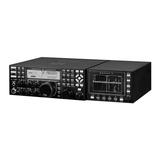
Quick-Start Guide To get started using your P3 right away, please read this page and the two pages that follow, trying each of the controls. The text uses braces to refer to numbered elements in the front- and rear-panel illustrations below. For example, {1} refers to , the display. - Page 5 Turn on the power supply that is supplying the P3. If power is obtained from the 12VDC The Basics OUT jack of a K3, turn on the K3. If necessary, press POWER {2} to turn on the P3. You can position a jumper to have the P3 turn on automatically with the K3 (Pg 18).
- Page 6 Other Hold {7} to toggle on or off the function key labels located at the bottom of the L AB E L S Features screen, just above the function keys (Pgs 11 and 12). {7} and use the knob {8} to scroll through the list.
-
Page 7: Introduction
Up to 200 kHz span. Frequency resolution automatically P3 Features increases as span is decreased. Excellent sensitivity and dynamic range. The P3 offers a number of advanced features to enhance performance and versatility: Ergonomic Design Compatible Receivers/Transceivers Uncluttered interface. ... -
Page 8: Specifications
Specifications I.F. Frequency Range: 455 kHz to 21.7 MHz (usable with frequencies as low as 300 kHz) Noise Figure: < 10 dB measured at P3 input typical Blocking Dynamic Range: > 120 dB (500 Hz bandwidth) typical Absolute Level Accuracy: ±... -
Page 9: Customer Service And Support
Elecraft products transferred by the purchaser to a third party, either by sale, gift, or other method, who is not disclosed to Elecraft at the time of original order, are not covered by this warranty. If the Elecraft product is being bought indirectly for a third party, the third party’s name and address must be provided at time of order to ensure... -
Page 10: Front Panel
Front Panel This reference section describes all front panel controls and the liquid crystal display (LCD). Operating instructions are covered in later sections. Control Groups Primary controls (pg 11): These keys are hard- Programmable function keys (pg 12): The coded with permanent function assignments. They function keys may be assigned to any of the provide the most important operational features functions in the MENU list. -
Page 11: Display
M E N U needed by the operator. All graphics and text are Primary Controls Turns the P3 on or off. The P3 may be correspondence. Whichever marker is currently P O W E R selected is the one that causes the K3 to QSY. To... -
Page 12: Menu
Sets the center frequency of the display, C E N T E R Toggles between the spectrum, and D I S P L AY which is also displayed at the top center of the combination spectrum/waterfall display modes. spectrum window. If the transceiver is a K3, the Turns on display averaging and allows center frequency equals the VFO A frequency of AV E R AG E... -
Page 13: Rear Panel Connectors
10-15 VDC supply capable of the ON position, the IF IN signal is directed to a 3 delivering up to 0.5A. dB splitter whose outputs feed both the P3 and the SENSOR. Keyboard, Ext Display and Aux Data: IF OUT connector. -
Page 14: Basic Operation
Connect a power supply, I.F. input and (optionally) an RS-232 cable (pg 13). Press to turn the P3 on, if it is not on P O W E R Typical Display Showing a Menu Selection already. The display should light and you should see a spectrum and/or waterfall. - Page 15 Programmable Functions Adjusting the Frequencies Displayed to adjust the range of frequencies that S P AN Any MENU function that you'd like quick access to can be seen on the display at one time. The start can be assigned to any programmable function key, and stop frequencies (calculated as offsets from the FN1 to FN8, by tapping or holding the desired center frequency) are shown at the top left and right...
- Page 16 Using Markers Waterfall Markers to turn on marker A and allow you to Select MENU:WfallMkrs . Turning the M K R A change the marker frequency by rotating the SELECT knob will turn the waterfall markers knob. To determine the frequency of a SELECT on, causing the marker line(s) to travel down into signal, move the marker so that it overlays the...
-
Page 17: Advanced Operating Features
Tester tab in P3 Utility. When the P3's XCVR RS- left on the display. 232 port is connected to a K3, then both P3 and K3 commands may be sent and received via the PC RS- If the correct I.F. is not in the list, the frequency of 232 port. -
Page 18: Firmware Upgrades
Please visit the Elecraft K3 software page powered from the auxiliary jack on a transceiver (www.elecraft.com) to obtain our free firmware such as the Elecraft K3 so the P3 turns on with the download application, P3 Utility. Versions of the transceiver. -
Page 19: Frequency Calibration Procedure
Depending upon the modulation mode of the transceiver, the signal may not be audible. Set the P3 for minimum span and adjust the reference level and scale so you can easily see the signal. ... -
Page 20: Menu Functions
SpanScale REF LVL Specifies the way the P3 responds to changes in SPAN. "Off" means do not only change REF_LVL or SCALE when SPAN is changed. "REF LVL only" means change the reference level to keep the noise level approximately constant. "REF LVL &... -
Page 21: Troubleshooting
Write down your function (FN) key assignments and MENU parameters you have set. They will be lost during the process. Turn the P3 OFF (using the P3’s POWER switch, not your power supply). If the power-on jumper on the I/O board is in the "always-on" position (pg 18), then skip this step. ... -
Page 22: Theory Of Operation
+12 VDC input. The input power is approximately independent of the voltage, which means the lower the input voltage the higher the current. While the P3 will typically work with input voltages of less than 8 V, the current may exceed the 0.5 A specification at that voltage. -
Page 23: Appendix A Parts List
Appendix A Parts List P3 Sheet Metal Box - E850435 P3 Side Panel Assembly – E850428 ELECRAFT ILLUSTRATION DESCRIPTION QTY. PART NO. Side Panel E100361 P3 Cover Assembly – E850429 ELECRAFT ILLUSTRATION DESCRIPTION QTY. PART NO. Top Cover E100362 Bottom Cover... - Page 24 P3 Rear Panel Assembly – E850431 ELECRAFT ILLUSTRATION DESCRIPTION QTY. PART NO. Rear Panel E100365 P3 Misc Bag - E850433 P3 Chassis Hardware – E850409 ELECRAFT ILLUSTRATION DESCRIPTION QTY. PART NO. 2-D Fastener E100078 L-Bracket E700073 Jackscrew Nut, 4-40 E700078 Screw, Pan Head, Zinc, 4-40 7/16”...
- Page 25 RF Cable, BNC – BNC, 36” (91.5 cm) E980170 TMP Cable, 10” (25.4 cm) E850338 DE9 Cable M-F, 36” (91.5 cm) E980169 Note: Some cables may have packages showing the original vendor’s part number instead of the Elecraft part number.
- Page 26 ILLUSTRATION DESCRIPTION QTY. PART NO. Serial Number Label E850437 (in protective envelope) P3 Front Panel Board with LCD and Switch Matrix. IMPORTANT: The display is easily dislodged from E850426 the assembly and damaged. Leave it in its protective wrapping until instructed to remove it.
-
Page 27: Appendix B - Kit Assembly Instructions
If you choose to use a soldering iron to work on your P3 for any reason, be sure your iron has an ESD- safe grounded tip tied to the same common ground used by your mat or wrist strap. -
Page 28: Tools Required
The circuit boards are mounted on the front and rear panels and interconnected by cables as shown in Figure 1. The enclosure uses Elecraft’s 2D fasteners at the corners of the panels which allow removing any combination of panels to gain access to the interior. - Page 29 (see Figure 2) and is easily dislodged until it is installed in the P3. Take care not to pull the display free as you may damage the connections to the printed circuit board behind it.
- Page 30 Remove the plastic display bezel from its protective wrapping and inspect it for dirt and dust, especially on the flat side that will face the display panel. Use a soft cloth if necessary to remove any objects clinging to the plastic.
- Page 31 Mount a 2D fastener at the top of the front panel assembly as shown in Figure 6. Do not use a lock washer. The 2D fasteners must always be oriented so the wide side of the fastener is toward the outside as shown. Tighten the fastener only enough to hold it in place.
- Page 32 At the front end of the bottom cover, install the two feet and tilt stand as shown in Figure 8. Position the tilt stand between the feet before mounting the feet on the bottom cover. Use 4-40 7/16” (11 mm) zinc pan head screws with inside tooth lock washers and nuts just as you did for the rear feet.
- Page 33 Remove the I/O printed circuit assembly from its anti-static packaging and inspect the two multi-pin connectors. These are the nuts the jack screws on the connector shells screw into to secure them. If either connector has jack screw nuts installed, remove them (see Figure 10) . Figure 10.
- Page 34 Mount the rear panel assembly to the end of the bottom cover that has the two round feet using a 3/16” (4.8 mm) pan head screw into each 2D fastener. CAUTION: Severe damage to your P3 may occur if the 40-conductor ribbon cable is not oriented correctly and properly mated to the connectors as described in the following steps.
- Page 35 For normal power switch operation, place it on pins 3 and 4. To bypass the power switch so the P3 is on whenever power is applied such...
- Page 36 Remove the protective backing from the Serial Number label and mount it on the rear panel where it won’t interfere with the silk-screened legends. Be sure you position so it’s aligned with the edges of the panel. Press it with your fingers to make it adhere permanently. That completes the assembly of your P3 Panadapter kit. B-10...
Need help?
Do you have a question about the P3 and is the answer not in the manual?
Questions and answers