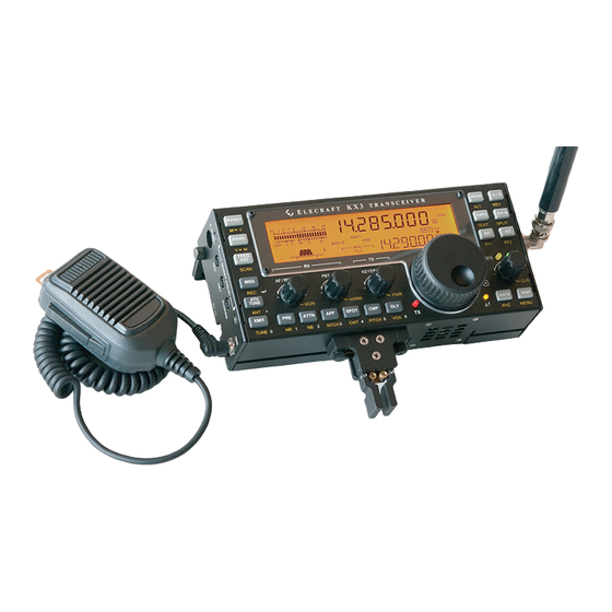
ELECRAFT KX3 Owner's Manual
Ultra-portable 160-6 meter, all-mode transceiver
Hide thumbs
Also See for KX3:
- Assembly manual (52 pages) ,
- Installation and operation manual (17 pages) ,
- Installation instructions manual (14 pages)

Related Manuals for ELECRAFT KX3


Summary of Contents for ELECRAFT KX3
- Page 1 LECRAFT LTRA PORTABLE 160-6 METER MODE RANSCEIVER ’ WNER ANUAL Revision B4, June 1, 2012 Copyright © 2012, Elecraft, Inc. All Rights Reserved...
-
Page 2: Table Of Contents
Firmware Upgrades........25 Antennas ..............6 SDR Applications ........26 Grounding and ESD Protection ......6 Control Panel Reference........ 7 Remote Control of the KX3 ......28 Display (LCD)............8 Configuration..........29 Basic Operation ..........9 Option Module Enables ........29 Menu Settings............29 Getting Started............9... -
Page 3: Introduction
Current drain is also very low for a full-featured transceiver, reflecting our commitment to field operation. For mobile and home use, you can boost the KX3’s output to 100 watts with the optional KXPA100 amplifier. -
Page 4: Installation
KXPD3 Keyer Paddle: The KXPD3 is an optional only the method shown. high-quality keyer paddle that attaches at the front of the KX3 via two thumb screws. The dot and dash The KX3 can be conveniently operated with paddles can be electrically reversed or configured one hand, in a manner similar to writing in a as a hand key using the CW KEY2 menu entry. -
Page 5: Headphones And Speakers
The 3.5-mm stereo ACC1 jack allows firmware angle plugs, are strongly recommended. updates, configuration, and remote control of the KX3 via a computer. The jack can be connected to a computer’s USB port via the Elecraft model Headphones and Speakers KXUSB cable, or to an RS232 port via the model KXSER cable. -
Page 6: Antennas
SWR of 1.0:1 ( on the KX3’s display) is 1 .0 - 1 be a set of wires tied together at one of the KX3’s considered a “perfect” match. To ensure safe ground points, then laid out on the ground in all operation, the KX3 reduces power if SWR is high. -
Page 7: Control Panel Reference
Control Panel Reference This section summarizes all KX3 controls. For details, see Basic Operation and Advanced Operating Features. To Turn Power ON/OFF: Hold both the switches for 2 seconds. ( label on left side.) See ON/OFF B A N D - A T U T U N E Tap Functions: Tap a switch or knob briefly to activate the function labeled on or above it, e.g. -
Page 8: Display (Lcd)
Display (LCD) Bar graph, receive mode: Normally acts VFO Icons: Shows that a VFO or menu as an S-meter. If is turned on, the C W T entry is locked. The icon points to the transmit right half of the S-meter becomes a tuning VFO: aid (pg. -
Page 9: Basic Operation
Each of the four small knobs has a primary function This section describes basic KX3 controls and that is in effect when you turn on the KX3. For features. Once you’ve mastered the basics, you’ll be example, the knob at far left,... -
Page 10: Band Selection
Many repeaters can be found on the 2-meter band (144-148 MHz), which is covered by the KX3-2M option module (pg. 25). If you don’t plan to operate in AM or FM modes, you can turn them off individually using the AM MODE and FM MODE menu entries (pg. -
Page 11: Vfos A And B
VFO A / B frequencies, modes, and all other settings. The KX3 provides two VFOs (see glossary, pg. 49). VFO A/B temporary reverse: Sometimes you’ll Use of VFO B is optional. The VFO knobs are want to swap the VFOs temporarily to look for an located in the area shown below. -
Page 12: Receive Settings
Receive Settings Passband Tuning Functions (PBT I/II) The RX control group, shown below, is used to set control is used to shape the KX3’s P B T I / I I up the KX3’s receiver. Directly above these receive filter passband. In general, a narrow... - Page 13 When you hold , the upper half of the S-meter C W T The KX3 will automatically reduce receive gain becomes a receive VFO tuning aid for CW and in the presence of very strong signals. The receive some data modes.
-
Page 14: Transmit Settings
Transmit Settings The TX control group is used to set up the KX3’s selects the keying mode: PTT (push-to-talk) V O X transmitter. The TX LED turns on during transmit. or VOX (voice- or keying-operated transmit). With PTT selected, the transmitter is enabled by tapping or by holding the mic’s PTT button. -
Page 15: Voice Modes (Ssb, Am, Fm)
P W R AM Operation Voice Mode VOX Setup AM receive on the KX3 uses traditional envelope detection. You can also listen to AM signals using selects push-to-talk (PTT) or voice-operated V O X LSB or USB modes, which may provide better copy (VOX) transmit ( icon on). -
Page 16: Cw Mode
CW Mode CWT, SPOT and Auto-Spot When calling a station, you should try to match Basic CW-Mode Setup your frequency to theirs. To facilitate this, the KX3 Mode selection: Tap to select provides both manual and automatic spotting for M O D E (CW normal). -
Page 17: Advanced Operating Features
Advanced Operating Features Scanning Scanning allows the KX3 to tune any portion of a Frequency Memories band continuously. Normal scanning mutes the receiver until a modulated signal is found. “Live” The KX3 has 100 general-purpose frequency scanning keeps the receiver unmuted, and is... -
Page 18: Data Modes
5 watts or less is strongly recommended to keep distortion low. computer. All data modes are described below. To use PSK D, set up the KX3 as described at left 5.0 watts or lower is recommended in data for FSK D, but select the sub-mode. -
Page 19: Text Decode And Display
Text Decode And Display Split and XIT The KX3 can decode CW, PSK31 (PSK D) and Sometimes you’ll hear a DX station being called by RTTY (FSK D). CW speeds from about 8 to 70 many other stations. To ensure that he has a clear WPM can be decoded. -
Page 20: Audio Effects
If you have stereo headphones or stereo external The KX3 provides 8 bands of receive audio speakers, you can take advantage of the KX3’s DSP equalization via the RX EQ menu entry. RX EQ audio effects (AFX). These create an illusion of can compensate for physical acoustics (of the room, greater acoustic “space,”... -
Page 21: Ssb/Cw Vfo Offset
GPIO pin that can be used to select among multiple It is not necessary to use the microphone’s PTT transverters based on the band selected at the KX3. switch or the XMIT switch when recording a DVR This is further explained below. -
Page 22: Special Vfo B Displays
AGC off, as the signal may become reminder of a contest or operating schedule. very loud.) Measurement of receive sensitivity The alarm will turn the KX3 on if it occurs (MDS) requires a calibrated 1-µV signal source when power is off. -
Page 23: Internal Batteries
Internal Batteries The KX3’s internal battery pack can be used with eight 1.2-1.6 volt AA cells of any type. The pack typically provides 4-6 hours of casual operation, ideal for field use or as backup during power outages. An internal NiMH charger is also available (KXBC3, pg. -
Page 24: Vfo Friction Adjustment
(Re-tighten the set function switch; see pg. 19.) If the KX3 is turned screw each time so you can spin the knob.) Then off during charging, it will “hibernate,” showing the and replace the finger grip. -
Page 25: Options And Accessories
. The D I S P transceiver, if needed, can be obtained using the alarm can be used to turn the KX3 on at a specified SER NUM menu entry. time, or simply to remind the operator of a schedule or contest-start time. -
Page 26: Sdr Applications
Since the KX3’s RX I/Q signal is analog, it must be below the current KX3 frequency that another converted to a digital signal by means of an analog- signal is. - Page 27 USB or RS232 port on the computer (see pg. 5). The program should then correctly display the actual signal frequencies as you tune the KX3. You may also be able to tune the KX3 from the program, depending on the program’s features.
-
Page 28: Remote Control Of The Kx3
Using the KX3 as a Remote Front Panel If you’re not using such software, or if you’re not You can use the KX3 as a front panel for a remotely using a computer at all, you can still set up the KX3 located KX3 or K3. -
Page 29: Configuration
After changing menu settings, use KX3 Utility Some Menu Settings (beginning at right) should be to save your present configuration. The set up before you use the KX3 on the air. configuration can then be restored later if required. Option Module Enables... -
Page 30: Microphone Settings
O U T B A N D - HH/MM/SS (hours/minutes/seconds), respectively. Then use VFO A to adjust the value. KX3 Utility CW Iambic Mode can also be used to accurately set the time. and rotate VFO B to display the present... -
Page 31: Calibration
There is one exception: If you install a KXFL3 S P O T increase sidetone volume. See pg. 12. roofing filter during KX3 kit assembly, or install one in a factory assembled KX3 after initial Locate the I/II icons (right end of the filter purchase, you’ll need to perform the Receive... -
Page 32: Receive Sideband
No test equipment is required. Make sure nothing is connected to the KX3’s This calibration step must be performed BNC antenna jack. when a roofing filter module is installed or removed. -
Page 33: Transmit Gain
Automated Transmit Gain Calibration If a computer is available, you can use the automated transmit gain calibration procedure. Connect the KX3 to the computer, run KX3 Utility, and select the Calibration tab. Click on Calibrate Transmitter Gain and follow the on-screen instructions. -
Page 34: Transmit Carrier
Transmit Carrier Transmit Sideband In SSB and some data modes, a transmitter’s In SSB and some data modes, a transmitter’s primary signal may be accompanied by a weak primary signal may be accompanied by a weak unmodulated signal called a carrier about 1 kHz opposite sideband signal about 2 kHz away. -
Page 35: Menu Functions
Menu Functions Hold to enter the KX3’s menu. Tap or hold this switch to exit. Menu entries that you’d like quick M E N U access to can be assigned to programmable function switches (pg. 19). Note: appears in some parameter N O R displays. - Page 36 Otherwise the time registers will reset to on power-up. 0 0 : 0 0 : 0 0 At the alarm time, the KX3 will emit three short beeps. If power had been turned off, AF output will then be restored to the last-used level. AM MODE Set to if AM operation is not planned.
- Page 37 If your mic has both a PTT switch and UP/DN buttons, set the parameter to MIC BTN . This applies to the Elecraft MH3. If the mic has PTT but no UP/DN UP.DN PTT UP.DN buttons, use .
- Page 38 KX3 nearby other receivers operating on the same band, and a strong carrier from the KX3 is heard when its VFO is tuned to the same frequency as the other receiver’s. The isolation amplifier is between the antenna jack and the mixer, preventing leakage from the KX3’s local oscillator.
- Page 39 (The full list of Morse code control characters, as well as a text-only panel description for blind operators, can be found on our KX3 web page.) Switch tone volume is the same as CW sidetone volume. It must be adjusted in...
- Page 40 (tip=auxBus, ring=key out). TRN0 is used with the KX3-2M module (internal). – to select the transverter band; rotate VFO A to select the address. To configure an Elecraft KX3-2M 2 m module as XVTR band 1, set XV1 ON to , XV1 RF to MHz, XV1 IF to MHz, and XV1 ADR to .
-
Page 41: Troubleshooting
Display backlight turns on, but then turns off on release of switches: Disconnect all external equipment from the KX3. Verify power supply or battery voltage is between 9 and 15 V. Open enclosure and make sure cable between the two main PC boards is fully plugged in at both ends. - Page 42 20-dB preamp on the current band. See MENU:PREAMP.) The second step taken by the KX3, if necessary, is to turn on a 15-dB attenuator stage in the I.F. section, ahead of the receiver’s A- to-D converter. The receive overload icon ( ), near the icon, will turn on.
-
Page 43: Parameter Initialization (Eeinit)
KX3 VFO signal is heard in a nearby receiver: If a nearby receiver is picking up the KX3’s VFO signal, turn on the isolation amp (RX ISO menu entry). Note: This increases current drain by about 15 mA if the isolation amp was not already being used as a 10-dB preamp. -
Page 44: Error Messages (Err Nnn)
Turn power off for 10 seconds, then back on. Reload MCU and DSP firmware. If this doesn’t correct the ERR DS2 DSP SPI echo not inverted problem, save your configuration using KX3 Utility, then ERR DSE DSP command timeout perform an EEINIT (pg. 43). If this corrects the problem,... - Page 45 ERR IOA RF board I/O expander A or B Turn power off and open the KX3’s enclosure. Make sure ERR IOB unresponsive. the cable between the Control Panel board and RF Board is fully seated at both ends and is not damaged in any way.
-
Page 46: Theory Of Operation
RF Board The RF PCB (Printed Circuit Board) contains all of the KX3’s RF circuitry as well as low-level baseband (AF) stages in the receive path. The Control Panel (CP) board (following page) generates all digital control signals for band switching, T/R, signal path routing, etc. -
Page 47: Control Panel (Cp) Board
AA cells (if applicable). The emphasis on the design is safety, so relatively low charging currents are employed. The KXBC3 also incorporates a real-time clock (RTC) function, useful for logging and time keeping. The RTC also allows the KX3 to function like a clock radio, turning itself on at a predetermined time (see the ALARM menu entry). -
Page 48: Kx3 Block Diagram
KX3 Block Diagram... -
Page 49: Glossary Of Selected Terms
The advantage of a DC-DC converter is that when it steps voltage down, it steps current up (or vice-versa). In this case, the 300 mA the KX3 consumes at 3.3 V might require only 100 mA at the 12-V power source. - Page 50 MDS (minimum discernable signal): A measure of a radio’s sensitivity, expressed in dB (decibels) relative to 1 milliwatt (0 dBm). For example, the user of a KX3 with the 20-dB preamp turned on, can typically copy a CW signal at about -137 dBm, or 137 dB below 1 milliwatt.
-
Page 51: Specifications
TRANSMITTER* Output Power 10 W PEP, 160-15 m; 8 W PEP, 12-6 m; 2 m (KX3-2M): TBD W, 144-148 MHz 5 W or less recommended for high-duty-cycle modes (FM, AM, DATA). Power will automatically be reduced if PA temperature or current limits are exceeded. -
Page 52: Customer Service And Support
Elecraft products transferred by the purchaser to a third party, either by sale, gift, or other method, who is not disclosed to Elecraft at the time of original order, are not covered by this warranty. If the Elecraft product is being bought indirectly for a third party, the third party’s name and address must be provided at time of order to ensure... -
Page 53: Index
Keyer Paddle, 4, 16, 37 CW Mode, 16 Keying Weight, 16 CW Reverse, 8 KSYN3, 48 CW, Break-In (QSK), 14, 16 KX3 Utility PC Application, 25, 28, 43 CW, Off-Air Keying, 35 KX3-2M, 25, 29 CW, Sending in SSB mode, 37 KXAT3, 25, 29... - Page 54 KXBC3, 24, 25, 29 Remote Control, 28 KXFL3, 25, 29 Repeater Offset, 15, 38 KXPA100, 29 Repeater Operation, 15 KXPD3, 25, 29 REV switch, 19 LCD Test, 37 RF Board, 46 Low Battery Warning, 29, 41 RF Gain Control, 12 Low-Pass Filter, 45 RIT, 40 Memories, 17...
- Page 55 Transverter Operation, 21 VFO Counts per Turn, 40 Troubleshooting, 41 VFO Setup, 30 Tune Power, 30, 39 VFO Tuning Controls, 11, 30, 40 Tuning Rate, VFO, 30, 40 Voice Modes, 15 TX EQ, 20, 39 VOX, Voice Modes, 14, 15, 30 TX LED, 25, 41 Warranty, 52 Universal Serial Bus (USB), 5...
Need help?
Do you have a question about the KX3 and is the answer not in the manual?
Questions and answers