suprema BioLite Net User Manual
Ip based outdoor fingerprint terminal
Hide thumbs
Also See for BioLite Net:
- User manual (23 pages) ,
- User manual (22 pages) ,
- Installation manual (19 pages)

Related Manuals for suprema BioLite Net


Summary of Contents for suprema BioLite Net
- Page 1 Manual er under oversettelse til norsk. Inntil videre bruk engelsk manual som starter på neste side. ...
- Page 3 This manual is provided for information purpose only. All information included herein is subject to change without notice. Suprema is not responsible for any changes, direct or indirect, arising from or related to us of this manual. ⓒ Copyright 2008 Supremainc. All rights reserved.
-
Page 4: Table Of Contents
Contents Safety Instructions ....................5 1. Before Use ......................6 1.1 Components ........................6 1.2 Body..........................7 1.3 Methods for fingerprint input .....................8 1.4 System setup procedure....................10 1.4.1 Registering the initial administrator ................11 1.4.2 Network configuration....................12 1.4.3 Stand-alone configuration..................15 1.4.4 Configuring Secure I/O.....................17 1.4.5 Configuring environment settings................18 1.5 Authorization methods ....................19 1.5.1 Finger Only.......................19 1.5.2 Finger or PIN ......................20... - Page 5 6. FAQ........................61 6.1 Error messages......................61 6.2 Troubleshooting ......................62 6.3 Usage summary ......................63 6.4 System Installation ......................64 6.4.1 Cable specifications....................64 6.4.2 Installing the bracket....................65 6.4.3 Connecting Power & RS-485................... 66 6.4.4 Connecting the switch....................66 6.4.5 Connecting the relay....................
-
Page 6: Safety Instructions
Safety Instructions Installation Do not arbitrarily install or Use the power adapter repair the product. provided or one for 12V 0.5A or above. The warranty does not apply to any product damage When sharing the power with caused by an other devices such as electric arbitrary door lock, check the power... -
Page 7: Before Use
1. Before Use 1.1 Components Main Body Wall mounting bracket Extended bracket (Option) Fixing Screws Knife Blocks Shrinkable Ethernet Connector (2 EA) (2 EA) Tubes Star-shape wrench Adapter (For fixing bracket) (Option) The components shown above may differ depending on the installation environment. -
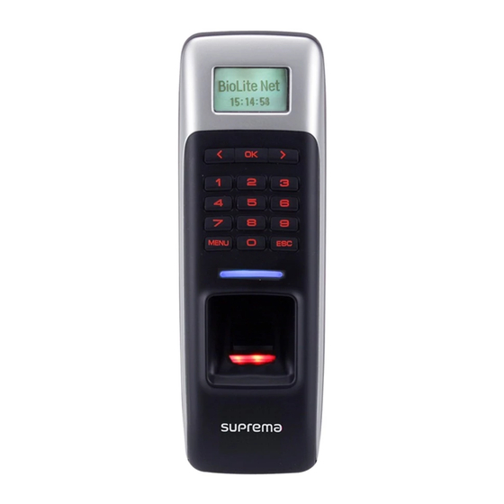
Page 8: Body
1.2 Body LCD Display Key Pad LED Lamp Fingerprint Touch Area (5) RF Card reading part Name Description The operation status is displayed. LCD Display Key Pad 0–9 Buttons: Used to enter the ID and password. < > Arrow Buttons: Used to move the selected item. Button: Used to select the desired function. -
Page 9: Methods For Fingerprint Input
1.3 Methods for fingerprint input BioLite Net can easily recognize fingerprints even though the angle and location of the pattern change. However, it is recommended to properly input fingerprints for more precise recognition. Selecting a finger on fingerprint enrollment Up to two fingerprints can be enrolled for each user in preparation of any abnormal situation like having a wounded finger or carrying an object with a hand. - Page 10 In case fingerprint is not recognized normally BioLite Net is designed to normally operate regardless of weather change or the angle and location of the fingerprint to place. However, the recognition rate may vary depending on the external environment or fingerprint condition.
-
Page 11: System Setup Procedure
1.4 System setup procedure Install the system according to the environment Step 1 - Grasp the locations for installation site, door open switch, dead bolt, and such. - Install the system (see 6.4). Register an initial administrator Step 2 - Register the initial administrator for setting devices (See 1.4.1). Configure the system Step 3 - Network configuration (see 1.4.2) -
Page 12: Registering The Initial Administrator
1.4.1 Registering the initial administrator There is no administrator set for the product in the initial status. So register an administrator for configuring the environments for relay, door open switch, door open detection sensor, and such. When the product is connected, a window Enter ID appears as shown in the right figure. -
Page 13: Network Configuration
1.4.2 Network configuration The network configuration is required to connect the dedicated PC software or other devices via network. Configure the settings according to the communication environment in your place. [In case of configuring the network via Ethernet] Connect the terminal to the computer that has the dedicated PC software according to the network environment after seeing “6.4.6 Connecting network.”... - Page 14 100Base-T support Not support Completed TCP/IP Use ◀/▶ buttons to The completion set whether or not to message window support 100Base-T appears. and press OK. When you exit from the menu before completing the TCP/IP setting, the data is not stored so please finish the remaining steps until the setting completion message appears.
- Page 15 [In case of configuring the network via RS-485] Connect the terminal to the computer that has the dedicated PC software or to another device according to the network environment after seeing “6.4.3 Connecting Power & RS-485.” Configure the settings for RS-485 according to the installation environment. Item Serial Conn.
-
Page 16: Stand-Alone Configuration
This configuration is required to use the device for stand alone purpose, which requires no communication with PC or other devices. As shown in the figure, connect BioLite Net to respective switches. For actual wring method, see “6.4 System Installation.”. - Page 17 Door Sensor Type Opening Mode Input 1 Temporary Open Internal Door Sensor Door Use ◀/▶ buttons to Use ◀/▶ buttons to Use ◀/▶ buttons to select Input 1 and press select N.O and press select Temporary Open for opening mode and press OK.
-
Page 18: Configuring Secure I/O
1.4.4 Configuring Secure I/O This connects BioLite Net to Secure I/O. Connect wires between BioLite Net, Secure I/O, and respective switches as shown below. For actual wiring, see “6.4 System Installation.” Configure the relay settings as shown below. (Based on the figure above) Follow the instructions below only when the dedicated PC software is not used. -
Page 19: Configuring Environment Settings
Door Sensor Type Opening Mode SIO Input 1 Temporary Open SIO Relay 0 Door Sensor Door Use ◀/▶ buttons to Use ◀/▶ buttons to Use ◀/▶ buttons to select SIO Input 1 and select N.O and press select Temporary Open press OK. -
Page 20: Authorization Methods
1. Fingerprint recognition 2. Fingerprint recognition after entering ID 3. Fingerprint recognition after identifying user card Fingerprint recognition BioLite Net Access Granted 10:33:02 ID : 2 Input the fingerprint of The door is open with the user. -
Page 21: Finger Or Pin
Fingerprint recognition after identifying user card BioLite Net 10:33:02 Place the user card on the Input the fingerprint SUPREMA logo area. of the user. Access Granted ID : 2 The door is open with the authentication success message. 1.5.2 Finger or PIN When the user authorization method is set to “Finger or PIN,”... - Page 22 Fingerprint recognition after entering ID Enter ID BioLite Net 10:33:02 Enter the ID of the Input the fingerprint of user and press OK. the user. Access Granted ID : 2 The door is open with the authentication success message. PIN entry after entering ID...
- Page 23 PIN entry after identifying the user card Enter Finger or PIN BioLite Net **** 10:33:02 Enter the password of the user and Place the user card on the press OK. SUPREMA logo area. Access Granted ID : 2 The door is open with the authentication success message.
-
Page 24: Finger And Pin
1. PIN entry after identifying fingerprint 2. PIN entry after entering ID and fingerprint 3. PIN entry after entering user card and fingerprint PIN entry after identifying fingerprint Enter PIN BioLite Net **** 10:33:02 Input the fingerprint Enter the password of the user. -
Page 25: Pin Only
PIN entry after entering user card and fingerprint BioLite Net 10:33:02 Input the fingerprint Place the user card on the of the user. SUPREMA logo area. Enter PIN Access Granted **** ID : 2 Enter the password The door is open with the of the user and authentication success message. -
Page 26: Card Only
PIN entry after identifying user card Enter Finger or PIN BioLite Net **** 10:33:02 Enter the password Place the user card on the of the user and SUPREMA logo area. press OK. Access Granted ID : 2 The door is open with the authentication success message. -
Page 27: User Management
2. User Management The user management and other environment settings can be updated after authorizing the registered administrator (see 1.4.1 “Registering the initial administrator”). 2.1 Enrolling a user 2.1.1 Registration on the terminal The information of a new user can be saved on the terminal. Use ◀/▶... - Page 28 Facility Code Enroll Use ◀/▶ buttons When identified, enter Place the user card on the to select Read Card the Facility Code. SUPREMA logo area. and press OK. In case of Manual Input Facility Code (0-255) Card Card ID 2691057484...
- Page 29 Enter the finger or PIN depending on the operation mode. (Password: 4–8 digit number, Fingerprint: 1 finger or 1 fingers) Enter the required information after selecting Device > Authorization > Operation Mode > Auth Mode. Finger Only/Finger or PIN/Finger and PIN Place the second Place the first Place the first...
-
Page 30: Registration On The Card
2.1.2 Registration on the card The information of a new user can be saved on a card. Use ◀/▶ buttons to select the User ( ) icon and press OK. User Use ◀/▶ buttons to select Enroll ( ) icon and press OK. - Page 31 Use ◀/▶ buttons to select Access Group Select and press OK. Full Access Access Group1 Use ◀/▶ button to select Card Type and press Card Type Bypass Card ※ Bypass Card/Use Template Enroll ※Card: Bypass Card/Use Template Bypass Card: User can be authorized using a card only. The user information is saved by touching the card.
-
Page 32: Editing A User Data
2.2 Editing a user data You can modify the data of the previously enrolled user. Use ◀/▶ buttons to select the User ( ) icon and press OK. User Use ◀/▶ buttons to select the Edit ( ) icon and press OK. Edit Enter the ID or fingerprint of the desired user and Enter ID/Finger... -
Page 33: Security Level
Changing the authorization method Item Operation Mode Finger Only Operation Mode Edit Edit Use ◀/▶ buttons to Use ◀/▶ buttons Press OK. select Operation Mode to select an desired and press OK. operation mode and press OK. This authorization method setting for each user has higher priority than the terminal setting that has been defined in Device >... - Page 34 Changing the fingerprint of the user Item Place the first Place the first Fingerprint finger finger again Edit Use ◀/▶ buttons to Place the first finger on Place the same finger select Fingerprint and the sensor. on the sensor again. press OK.
- Page 35 Changing the card Item Card Card Read Card Edit Edit Use ◀/▶ Use ◀/▶buttons to Press OK. buttons to select select card input type Card and press * Not use/ Read Card/ Manual Input / User ID *Not use/Read Card/Manual Input/User ID ※Card: - Not use: Card is not used Read Card: User information is changed after touching a card on the terminal.
-
Page 36: Deleting A User Data
2.3 Deleting a user data You can delete unnecessary user data. Use ◀/▶ buttons to select the User ( ) icon and press OK. User Use ◀/▶ buttons to select the Delete ( ) icon and press OK. Delete After entering the ID or finger to delete and press Enter ID/Finger Delete When the action is successfully made, the... -
Page 37: Configuration For Screen And Sound
3. Configuration for Screen and Sound 3.1 Date, Time You need to set the current system date and time. After setting the date and time, the log data can store correct information. Use ◀/▶ buttons to select the Screen, Sound ) icon and press OK. -
Page 38: Backlight
3.2 Backlight Use ◀/▶ buttons to select the Screen, Sound ) icon and press OK. Screen, Sound Use ◀/▶ buttons to select Backlight ( ) icon and press OK. Backlight Use ◀/▶ buttons to select a backlight operation Mode status and press OK. All On At use Backlight All On At Use (FW V1.21 or later) - Page 39 ※When no input is made on the menu window, it sets On at Use the time to automatically turn off the LCD backlight. Mode Timeout(sec) On at Use Backlight Backlight Use ◀/▶ buttons to Enter the backlight-on time select the On at Use and (second) on the menu window.
-
Page 40: Sound
3.3 Sound Use ◀/▶ buttons to select the Screen, Sound ) icon and press OK. Screen, Sound Use ◀/▶ buttons to select Sound ( ) icon and press OK. Sound Use ◀/▶ buttons to select the sound operation status and press OK. Mode Mode Sound... -
Page 41: Device Configuration
4. Device Configuration 4.1 Authorization Use ◀/▶ buttons to select the Device ( ) icon and press OK. Device Use ◀/▶ buttons to select the Authorization ) icon and press OK. Authorization Use ◀/▶ buttons to select any of Fingerprint, Item and Operation Mode and press OK. - Page 42 Item Sensitivity Sensitivity Fingerprint Fingerprint Use ◀/▶ buttons to Use ◀/▶ buttons to select Sensitivity and select Sensitivity level press OK. and press OK. Item Check Duplicate Check Duplicate Not Use Fingerprint Fingerprint Use ◀/▶ buttons to Use ◀/▶ buttons Check select Check Duplicate Duplicate and press OK.
- Page 43 If this time limit expires, matching stops and the authorization fails. ※ Template Type : Format used in the terminal when identifying fingerprints (SUPREMA/SIF) - SUPREMA: SUPREMA’s own template format, SIF: ISO/IEC compatible template format (To change the template format, there must be no fingerprint data stored on the terminal.)
- Page 44 In case of Operation Mode Item Use ◀/▶ buttons to select Operation Operation Mode Mode an press OK. Authorization Item Schedule Sensor Mode Sensor Mode Always On All Time Operation Mode Always On Operation Mode Use ◀/▶ buttons to Use ◀/▶ buttons to ◀...
- Page 45 * Use Template/Use CSN ※Card entry methods (Available in BioLite Net Mifare): - Use Template : After placing the user card, enter your fingerprint and PIN. Then the terminal matches the enrolled fingerprint template with the template in the card for identification.
-
Page 46: In/Out
4.2 In/Out Use ◀/▶ buttons to select the Device ( ) icon and press OK. Device Use ◀/▶ buttons to select In/Out ( ) icon and press OK. In/Out Use ◀/▶ buttons to select any of Serial Conn., Item Tamper On, Door Wiegand, and TCP/IP and Serial Conn. - Page 47 Termination Type Ext. Slave Not Use Completed Serial Conn Serial Conn. ◀ ▶ Use ◀/▶ buttons to buttons to The completion select Ext. Slave and whether or not to use the message window press OK. termination and press OK. appears. Type Termination Not Use...
- Page 48 In case of Tamper On Item Tamper On Tamper On Ignore In/Out In/Out Use ◀/▶ buttons to Use ◀/▶ buttons Press OK. select Tamper On and to select a tamper press OK. method. ※ Tamper: *Ignore/Locked - Locked : When the device is forcibly removed, the Device is locked. (To release the lock, the administrator must perform authorization.)
- Page 49 In case of Door (When using the internal relay) ※ It is used only when the stand-alone BioLite Net is installed without interoperating with the dedicated PC software. Relay Exit Button Item Internal Input 0 Door Door Internal In/Out Use ◀/▶ buttons Use ◀/▶...
- Page 50 In case of Door (When using the SIO relay) ※It is used only when the stand-alone BioLite Net is installed without interoperating with the dedicated PC software. Relay Item Exit Button SIO Relay0 Door SIO Input0 Door In/Out SIO Relay0 Use ◀/▶...
- Page 51 In case of Wiegand ※Standard 26Bit Format is used for Wiegand In/Out format. The setting can be changed using the dedicated PC software. Item Type Wiegand Card ID In In/Out Wiegand Use ◀/▶ buttons to ◀ ▶ buttons to select select Wiegand and Wiegand and press OK.
- Page 52 ※It directly connects to the server for the dedicated In case of TCP/IP PC software without using DHCP. Item DHCP IP Address TCP/IP Not Use 192.168.1.35 TCP/IP TCP/IP In/Out ◀ ▶ buttons to set Use ◀/▶ buttons to Enter IP address and select the TCP/IP and whether or not to use press OK.
-
Page 53: System
4.3 System . Use ◀/▶ buttons to select the Device ( ) icon and press OK. Device Use ◀/▶ buttons to select the System ( icon and press OK. System Item Use ◀/▶ buttons to select any of Information, Information Factory Default, Delete All Log, Delete User DB, and Language and press OK. - Page 54 In case of Information — Continued User Item 4/5000 Num. Of User Templates 6/10000 Information Use ◀/▶ buttons to The number of current users select Num. Of User and the number of fingerprints and press OK. enrolled appear. Item Firmware Ver. Firmware Ver.
- Page 55 In case of Delete All Log Delete? Item Delete Delete All Log Deletion Delete All Log System Use ◀/▶ buttons to Use ◀/▶ buttons In case of Delete, select Delete All Log and to determine the message press OK. whether or not to Deletion appears.
- Page 56 Use ◀/▶ buttons to Place the user card on After formatting a card, The select Format Card the SUPREMA logo area. format completion message and press OK. window appears. ※ After formatting a card, the data on a rewritable card such as Mifare card...
-
Page 57: Attendance Management
5. Attendance Management 5.1 Operating environment When an event (attendance, leaving, return, and outside duty) is received from the terminal, it is reported to the server of the dedicated PC software. You can create a report from the events stored in the server. With the dedicated PC software, you can also define new event other than the above- mentioned basic events and apply it to the report. -
Page 58: Setup For Attendance Management
5.2 Setup for attendance management Use ◀/▶ buttons to select the Device ( ) icon and press OK. Device Use ◀/▶ buttons to select the Authorization ) icon and press OK. Authorization Use ◀/▶ buttons to select the Operation Mode Item and press OK. -
Page 59: Operation Modes
5.3 Operation modes 5.3.1 Key Input When the operation mode is set to “Key Input,” this mode is used. Select BioLite Net 10:33:02 Type Select the desired Move to the desired event and perform event by using ◀/▶ user authorization. -
Page 60: Auto
In case of Manual ID: 8 08:30:43 12/01/2008 The door opens with a confirmation message. The Users identify the card or fingerprint according to the authorization method. Manual : It is convenient to those who need to change an event type manually ※... -
Page 61: Fixed
5.3.3 Fixed When the operation mode is set to “Fixed,” this mode is used. This mode is used after fixing the event through the dedicated PC software if required. In this case, the setting can be changed only through the dedicated PC software and you cannot change the attendance event through the terminal. -
Page 62: Faq
6. FAQ 6.1 Error messages Error Message Description !Access Restricted The authentication trial happens except for the allowed time zone. !Cannot Change A template already exists when you want to change the template format. !Cannot Format The card is not formatted due to improper card touch. !Cannot Write The user information is not saved due to improper card touch. -
Page 63: Troubleshooting
- If you cannot find the password, contact the pressing OK. administrator. The fingerprint has - BioLite Net has the technology of Suprema that won the been enrolled but its first award in FVC2004 and FVC2006 because it has recognition world number one quality in recognition. -
Page 64: Usage Summary
6.3 Usage summary ※ It provides the mainly used functions . button: Used to select the desired function. ※ Method for setting Function (Sequentially perform the following items.) Initial administrator Enter ID Enter password Enter password again registration Select Screen, Sound ( ) icon Select Date, Time ( ) icon Date &... -
Page 65: System Installation
6.4 System Installation 6.4.1 Cable specifications Type Name Color SWIN0 Purple Gray SWIN1 Brown Switch & Gray Wiegand W-DATA0 Green W-DATA1 White W-GND Black ERX - Yellow ERX + Blue Network ETX - Orange ETX + Pink Relay Normal Close Orange (White String) Relay Relay Common... -
Page 66: Installing The Bracket
6.4.2 Installing the bracket Fix the bracket to the place where BioLite Net is to be installed using the fixing screws. If the installation place is on concrete, drill holes, insert knife blocks into the holes, and fix them by using fixing screws. -
Page 67: Connecting Power & Rs-485
RS-485 is used for connecting to another device ※ (e.g. PC, BioStation, BioEntry Plus, BioLite Net, Secure I/O, etc.). For power supply, use a product of DC 12V (± 10%) and minimum 500mA. To share the power adapter with another device, the required current sum of terminal (500mA) and another device must not exceed the current capacity. -
Page 68: Connecting The Relay
6.4.5 Connecting the relay 1. Fail safe lock 2. Fail secure lock 3. Automatic door... -
Page 69: Connecting Network
6.4.6 Connecting Network 6.4.7 Connecting Wiegand When BioLite Net is used for When BioLite Net is used for Wiegand output device Wiegand input device... -
Page 70: Electrical Specifications
6.4.8 Electrical specifications Type Name Min. Typ. Max. Notes Power Voltage (V) 10.8 13.2 Use regulated DC power adaptor only Current (mA) Switch VIH (V) Input VIL (V) Pull-up 4.7k The input ports are resistance (Ω) pulled up with 4.7k resistors Relay Switching... -
Page 71: Specifications
(When sharing the power with a device such as electric door lock, Rated Voltage enough power is required considering the power requirement for the connected device.) 125kHz EM4100 Card (BioLite Net EM) Supportable Cards 13.56MHz Mifare Card (BioLite Net) Size... - Page 72 Mechanical Specifications...
-
Page 73: Fcc Notice
6.6 FCC Notice This equipment has been tested and found to comply with the limits for a Class B digital device, pursuant to part 15 of the FCC Rules. These limits are designed to provide reasonable protection against harmful interference in a residential installation. This equipment generates, uses and can radiate radio frequency energy and, if not installed and used in accordance with the instructions, may cause harmful interference to radio communications.
Need help?
Do you have a question about the BioLite Net and is the answer not in the manual?
Questions and answers