suprema BioLite Net Installation Manual
Ip fingerprint terminal
Hide thumbs
Also See for BioLite Net:
- User manual (74 pages) ,
- User manual (23 pages) ,
- User manual (22 pages)

Related Manuals for suprema BioLite Net


Summary of Contents for suprema BioLite Net
-
Page 1: Installation Guide
INSTALLATION GUIDE BioLite Net English Version 2.10 EN 101.00.BLN V2.10A... -
Page 2: Table Of Contents
Contents Safety Instructions ..................3 Getting Started ....................5 Components ..............................5 Part names and features ..........................6 Cables and connectors ..........................7 How to Scan a Fingerprint.......................... 8 Choosing a finger for registration ....................... 8 How to register a fingerprint ....................... 8 Installation ...................... -
Page 3: Safety Instructions
If installing the product outside where the product is completely exposed, it is recommended to install the product together with the enclosure. Use a separate power supply for Secure I/O 2, electric lock and BioLite Net respectively. • If connecting and using the power supply to these devices together, the devices may malfunction. -
Page 4: Operating Instructions
Safety Instructions Operating Instructions Do not drop the product or subject it to shock or impact during use. • This can cause a failure. Keep the password secret from others and change it periodically. • Failure to do so may lead to an illegal intrusion. Do not press the buttons on the product with excessive force or with a sharp tool. -
Page 5: Getting Started
Getting Started Getting Started Components BioLite Net Main bracket Extension bracket Mounting screws PVC anchors Heat shrink tubes TCP/IP connector for bracket (2 pcs) (2 pcs) Hex wrench Diode Adapter (for mounting bracket) (1 pc) Note The components may differ depending on where the product is installed. -
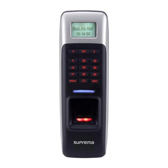
Page 6: Part Names And Features
Getting Started Part names and features LCD screen Keypad LED lamp Fingerprint reader RF card touch area Name Feature LCD screen Displays various information or settings. • 0–9 buttons: For entering an ID or password. • < > direction button: Navigates to an item. When entering numbers or an IP address, the < button can be used to delete the value entered. -
Page 7: Cables And Connectors
Getting Started Cables and connectors Name Color TTL IN0 Purple TTL GND Gray TTL IN1 Brown TTL GND Gray WG D0 Green WG D1 White WG GND Black ENET RXN Yellow ENET RXP Blue ENET TXN Orange ENET TXP Pink RLY NC Orange (White stripe) RLY COM... -
Page 8: How To Scan A Fingerprint
How to Scan a Fingerprint Register a fingerprint correctly to improve the recognition rate of the fingerprint. BioLite Net can read a fingerprint even when the angle or position of the finger has changed. If you register a fingerprint with the following instructions, the recognition rate can be improved. -
Page 9: Installation
With the mounting screws for the bracket, mount the bracket firmly onto the surface where BioLite Net is to be installed. Note If BioLite Net is to be installed on a concrete wall, make a hole with a drill, and then insert a PVC anchor into the hole before inserting the mounting screw. -
Page 10: Connecting To Power
(500 mA) and other devices. • Use a separate power supply for Secure I/O 2, electric lock and BioLite Net respectively. If connecting and using the power supply to these devices together, the devices may malfunction. -
Page 11: Connecting To A Relay
Install the diode close to the door lock device. • Use a separate power source for BioLite Net from the door lock device. Fail Secure Lock To use fail secure lock, connect N/O terminal as shown below. Normally, there is no current flowing through the relay and the door is opened when the relay is activated by a current flows. -
Page 12: Connecting To An Automatic Door
Green (White stripe) 14 - RLY NO Gray (White stripe) BioLite Net How to configure a Relay Set up the relay according to the following steps only when BioStar is not used to set up the door. Press the MENU button, and then authenticate with the administrator authentication method. -
Page 13: Connecting As A Standalone
4 - TTL GND Gray Relay 12 - RLY NC Orange (White stripe) 13 - RLY COM Green (White stripe) Door Lock BioLite Net Input 1 Door sensor Set up the relay. (Please refer to How to configure a Relay.) -
Page 14: Connecting To Secure I/O 2
Installation Connecting to Secure I/O 2 Here is how to install the device when BioLite Net is connected to Secure I/O 2. Refer to the following figure for connecting. • RS-485 should be AWG24, twisted pair, and maximum length is 1.2 km. -
Page 15: Product Specifications
Product Specifications Product Specifications Category Feature Specification Biometric Fingerprint IP Rating IP 65 Main RF Card 125KHz EM, 13.56MHz Mifare/DESFire Multi-Controller Max. User (1:1) 5,000 Max. User (1:N) 5,000 Capacity Max. Template (1:1) 10,000 Max. Template (1:N) 10,000 Max. Text Log 50,000 TCP/IP RS-485... -
Page 16: Dimensions
Product Specifications Dimensions Diameter 3.5 Diameter 4.5 Diameter 4.5 Extension bracket Main bracket... -
Page 17: Fcc Compliance Information
FCC Compliance Information FCC Compliance Information THIS DEVICE COMPLIES WITH PART 15 OF THE FCC RULES. Operation is subject to the following two conditions: (1) This device may not cause harmful interference, and (2) This device must accept any interference received, including interference that may cause undesired operation. Note: This equipment has been tested and found to comply with the limits for a Class B digital device, pursuant to part 15 of the FCC Rules. -
Page 18: Appendix
This document provides the information pertaining to Suprema's products. • The right of use is granted only to the products that are covered by the sales agreement and conditions guaranteed by Suprema. Any license of intellectual property that is not dealt within this document is not granted. - Page 19 www.supremainc.com www.supremainc.com...
Need help?
Do you have a question about the BioLite Net and is the answer not in the manual?
Questions and answers