Tennant T17 Operator's Manual
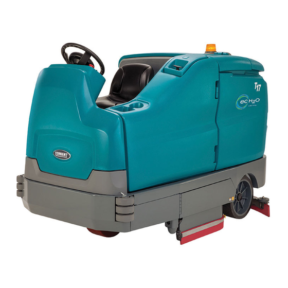
Rider scrubber
Hide thumbs
Also See for T17:
- Service information manual (182 pages) ,
- Operator's manual (150 pages) ,
- Instruction bulletin (15 pages)
Table of Contents
Advertisement
Quick Links
Advertisement
Table of Contents

Related Manuals for Tennant T17


Summary of Contents for Tennant T17
- Page 1 (Battery) Rider Scrubber Operator Manual Extended Scrub System TennantTrue Parts IRISt a Tennant Technology North America / International 9020160 For the latest parts manuals and other Rev. 03 (12-2015) language Operator manuals, visit: *9020160* www.tennantco.com/manuals...
- Page 2 Installation Date − INTENDED USE The T17 is an industrial/commercial rider machine designed to wet scrub both rough and smooth hard surfaces (concrete, tile, stone, synthetic, etc). Typical applications include schools, hospitals / health care facilities, office buildings, and retail centers. Do not use this machine on soil, grass, artificial turf, or carpeted surfaces. This machine is intended for indoor use only.
-
Page 3: Table Of Contents
Scrubbing Or Sweeping Side Brush (Option) ......Pre−Sweep Assembly (Option) ..T17 9020160 (12−2015) - Page 4 Ec−H2o System (Option) ....Machine Dimensions ....T17 9020160 (12−2015)
- Page 5 SAFETY PRECAUTIONS T17 9020160 (5−2014)
-
Page 6: Important Safety Instructions − Save These Instructions
− With pads or accessories not supplied WARNING: Batteries emit hydrogen gas. or approved by Tennant. The use of Explosion or fire can result. Keep other pads may impair safety. sparks and open flame away. Keep −... -
Page 7: Safety Precautions
− Always follow safety and traffic rules. − Do not modify the machine from its − Report machine damage or faulty original design. − Use Tennant supplied or approved operation immediately. − Follow mixing, handling and disposal replacement parts. − Wear personal protective equipment instructions on chemical containers. - Page 8 / step. detergent tank (option). FOR SAFETY LABEL − Read manual before operating machine. FOR SAFETY LABEL − Authorized Service Mechanic Only. Located on circuit board cover and electrical panel. Located on electrical panel. 356290 T17 9020160 (5−2014)
-
Page 9: Operation
H. Recovery tank drain hose T. ec−H20 System Module compartment (Option) − located behind I. Vacuum hose J. Rear squeegee right shroud K. Rear bumper door / step U. Overhead guard L. Steering wheel V. Backup alarm / flashing light (Option) T17 9020160 (12−2015) -
Page 10: Controls And Instruments
G. Scrubbing side brush switch (option) / Sweeping side brush switch (option) / Pre−Sweep switch (option) H. Severe environment switch I. Operating lights / hazard lights switch (option) J. Key switch K. Directional switch L. Emergency shut−off button T17 9020160 (5−2014) -
Page 11: Touch Panel
L. 1−Step button M. ec−H2O / ES (Extended Scrub) button N. Vacuum fan / squeegee button O. Solution increase button (+) P. Solution decrease button (−) Q. Solution on / off buttons R. Solution flow indicator lights T17 9020160 (5−2014) -
Page 12: Symbol Definitions
Main brush pressure Side brush (option) Solution On / Off Battery charge Emergency shut−off Horn Contrast control Hour meter Jack point Solution tank Solution flow (minimum / maximum) Forward / Reverse Brush pressure (minimum / maximum) Extended Scrub T17 9020160 (5−2014) -
Page 13: Operation Of Controls
See FAULT INDICATOR(S). HOUR METER The Hour meter records the hours the machine was operated. Use this information to determine machine service intervals. CONTRAST CONTROL BUTTON Use the Contrast control button to darken / lighten the LCD display. T17 9020160 (5−2014) -
Page 14: Configuration Mode Button
Lower squeegee and turn vacuum fans on: Press the configuration and diagnostic modes. Only the Vacuum fans / squeegee button. The indicator properly trained service personnel and TENNANT light will illuminate when the squeegee is lowered. representatives should access these modes. -
Page 15: Directional Switch
Operating and Hazard Lights On: Press the top of the Operating / hazard light switch. Hazard Lights On: Press the Operating / hazard light switch to the middle position. All Lights Off: Press the bottom of the Operating / hazard light switch. T17 9020160 (5−2014) -
Page 16: Propel Pedal
PARKING BRAKE PEDAL Position toe onto the Parking brake pedal and press both the Brake pedal and Parking brake pedal down to engage the parking brake. Press just the Brake pedal to release the parking brake. T17 9020160 (5−2014) -
Page 17: Rear Bumper Door / Step
NOTE: Step only in the tread area of the Rear bumper door / step. Do Not step into the two marked indented non−tread areas on each side of the Rear bumper door / step. T17 9020160 (5−2014) -
Page 18: How The Machine Works
The converted water attacks the dirt, breaks it into T17 With Cylindrical Brushes smaller particles, and pulls it off the floor surface allowing the machine to easily scrub away the suspended soil. -
Page 19: Brush And Pad Information
“tufts,” on the back to hold the * This brush is also available for the side brush. pad in place. This driver works with all Tennant pads except the black high productivity pad. Stripping pad (Brown)− For stripping of floor finish to prepare the floor for recoating. -
Page 20: While Operating The Machine
0_ C (32_ F). FOR SAFETY: When using machine, do not scrub on ramp inclines that exceed 8.7% grade or transport (GVWR) on ramp inclines that exceed 12% grade. T17 9020160 (5−2014) -
Page 21: Pre−Operation Checklist
- Machines equipped with ES option: Ensure ES filter at bottom of recovery tank is clean. - Check the right side squeegee for wear and damage. - Check the solution tank cover seal for wear or damage. T17 9020160 (5−2014) -
Page 22: Starting The Machine
3. Pour detergent into the detergent tank. needed to travel. 5. Press the Propel pedal to move the machine. NOTE: The machine will not travel unless the operator is sitting in the operator seat. 4. Reinstall the cap onto the detergent tank. T17 9020160 (5−2014) -
Page 23: Filling The Solution Tank
3. Close the solution tank cover. NOTE: Pour a recommended foam control solution into the recovery tank if excessive foam appears. For specific detergent recommendations, contact a Tennant representative. 3. Close the solution tank cover. T17 9020160 (12−2015) -
Page 24: Es (Extended Scrub) Mode − Manual Tank Fill
ES filter with water (not to exceed 60C / detergents. Machine damage due to the use of 140F). improper detergent will void the manufacturer’s warranty. 4. Raise the Rear bumper door / step. T17 9020160 (5−2014) -
Page 25: Ec−H2O Button (Option)
A flashing red light located on the bottom portion of the LED (light−emitting diode) light directly above the ec−H20 button indicates when the ec−H2O system needs to be flushed. See ec−H2O MODULE FLUSH PROCEDURE in the MAINTENANCE section. T17 9020160 (5−2014) -
Page 26: Setting Brush Pressure
The machine will The machine will default to the last setting used default to the last setting used when it is powered when the machine is powered on or off. on or off. T17 9020160 (5−2014) -
Page 27: Scrubbing
LCD, and an audible alarm), stop the machine and refer to the FAULT INDICATORS or WARNING CODES section of this manual for the cause and the corrective action for eliminating the fault or warning. T17 9020160 (12−2015) -
Page 28: Double Scrubbing
Solution on / off button Press the Solution on / off button again to restart the solution flow. NOTE: Double scrubbing is not recommended in areas where the cleaning solution will run under racks or damage products. T17 9020160 (5−2014) -
Page 29: Water Pickup Mode (No Scrubbing)
Do not pick up. Press the Vacuum fan/squeegee button. The light above the button will come on, the squeegee will lower, and the vacuum fan will start operating. Pick up the water or non−flammable liquid spill. T17 9020160 (5−2014) -
Page 30: Draining And Cleaning The Recovery Tank
4. Hold the drain hose near a floor drain, twist the drain nozzle open, and place the hose near the floor drain. NOTE: Be sure the drain hose nozzle is pointed in a safe direction before opening the nozzle. T17 9020160 (5−2014) - Page 31 12. Remove the debris tray from the recovery tank and rinse all debris from the tray. 9. Twist the drain cuff closed and insert the drain hose back into the clip on the recovery tank. 13. Close the recovery tank cover. T17 9020160 (5−2014)
- Page 32 NOTE: The scrub head must be lowered approximately 25 mm (1 in) to remove debris trough. NOTE: The debris trough can be removed from the right side of the machine only. 15. Raise the Rear bumper door / step. T17 9020160 (5−2014)
-
Page 33: Draining And Cleaning The Solution Tank
NOTE: Be sure the drain hose nozzle is pointed in a safe direction before opening the nozzle. NOTE: DO NOT use steam to clean the tanks. Excessive heat can damage the tanks and components. T17 9020160 (5−2014) -
Page 34: Turn Off The Machine
8. Twist the drain cuff closed and insert the drain hose back into the clip on the solution tank. 9. Raise the Rear bumper door / step. T17 9020160 (5−2014) -
Page 35: Fault Indicators
F4: F/L Br Flt## Front left brush not operating Turn off and restart machine. If fault code still appears, stop using machine and contact Tennant service representative F5: R/R Br Flt## Right rear brush not operating F6: Vac 1 Short... -
Page 36: Warning Codes
W7: Side Br Wrn## Scrubbing side brush Turn off and restart machine. inoperable. If fault code still appears, stop using machine and contact Tennant service W8: L Side Br Short Left sweeping side brush representative. inoperable. W9: R Side Br Short Right sweeping side brush inoperable. - Page 37 W21: Sweep Vac Shrt Pre−Sweep vacuum fan Turn off and restart machine. inoperable. If fault code still appears, stop using machine and contact Tennant service representative. W22: Open Vac 1 Vacuum fan 1 inoperable. Check corresponding circuit breaker. Check harness connection. Reconnect W23: Open Vac 2 Vacuum fan 2 inoperable.
-
Page 38: Options
NOTE: Be sure the Spray nozzle switch is turned off before continuing scrubbing. The spray nozzle pump could be damaged if the switch is left on while scrubbing. 3. Open the left shroud to access the spray nozzle. T17 9020160 (5−2014) -
Page 39: Vacuum Wand (Option)
5. Connect the vacuum wand nozzle to the vacuum wand nozzle hose. 3. Disconnect the vacuum hose from the rear squeegee. 6. Insert and tighten the vacuum wand handle into the vacuum wand nozzle. T17 9020160 (12−2015) - Page 40 17. Lift the rear bumper door / step to the raised position and secure to the rear bumper. 9. Turn on the machine. 10. Press the Vacuum fan/squeegee button to turn on the vacuum fan. The squeegee will completely lower. T17 9020160 (5−2014)
-
Page 41: Rear Squeegee Guard (Option)
NOTE: The 1−Step button controls the side brush assembly when the Side brush switch is in the On (top) position. 4. Press the Propel pedal to begin scrubbing. 5. Press the bottom of the Side brush switch to stop and raise the side brush. T17 9020160 (12−2015) -
Page 42: Pre−Sweep Assembly (Option)
3. Remove the debris hopper from the Pre−Sweep assembly and empty the hopper. 4. Press the illuminated portion (top or bottom) of the Pre−Sweep switch to shut off the Pre−sweep system and dust control system. T17 9020160 (5−2014) -
Page 43: Adjusting Backup Alarm Volume (Option)
85−102 dB(A). To adjust the volume, remove the backup alarm cover and turn the volume knob. Increase volume: Turn the knob clockwise. Decrease volume: Turn the knob counter−clockwise. 6. Disengage the Pre−Sweep cover support and lower the Pre−Sweep cover. T17 9020160 (12−2015) -
Page 44: Slide Out Battery (Option)
The machine will not function if the switch is not engaged. 3. Disconnect the battery cable from the machine connector. 9. Close the battery compartment side cover and top cover. T17 9020160 (5−2014) - Page 45 OPERATION T17 9020160 (5−2014)
-
Page 46: Machine Troubleshooting
Solution solenoid clogged or stuck Clean or replace Poor scrubbing performance Debris caught on scrub brushes Remove debris from brushes Improper detergent / brushes pads Contact Tennant representative for used recommendations Worn scrub brushes pads Replace scrub brushes / pads Excessive brush pressure... - Page 47 Mineral deposit build−up in module Flush module (See ec−H2O Warning and fault indicator MODULE FLUSH PROCEDURE) light blinking red ec−H2O Model: Clogged module Contact Tennant service Warning and fault indicator representative light solid red Defective solution pump Replace solution pump T17 9020160 (5−2014)
-
Page 48: Maintenance
MAINTENANCE MAINTENANCE 356389 356290 T17 9020160 (5−2014) -
Page 49: Maintenance Chart
LUBRICANT/FLUID ..Distilled water..Special lubricant, Lubriplate EMB grease (Tennant part number 01433−1) ..SAE 90 weight gear lubricant NOTE: More frequent maintenance intervals may be required in extremely dusty conditions. - Page 50 LUBRICANT/FLUID ..Distilled water..Special lubricant, Lubriplate EMB grease (Tennant part number 01433−1) ..SAE 90 weight gear lubricant NOTE: More frequent maintenance intervals may be required in extremely dusty conditions.
-
Page 51: Yellow Touch Points
STEERING CHAIN The steering chain is located on the steering column directly under the control panel. Check for damage or wear and lubricate the steering chain after every 200 hours. T17 9020160 (5−2014) -
Page 52: Batteries
Proceed to the BATTERY WATERING SYSTEM (OPTION). 08247 FOR SAFETY: When servicing machine, keep all metal objects off batteries. Avoid contact with battery acid. T17 9020160 (1−2015) -
Page 53: Charging The Batteries
NOTE: If there are charger fault codes when the battery is plugged into the battery charger, the fault codes will appear at the bottom of the charger display. Refer to the battery charger manual for fault code definitions. T17 9020160 (1−2015) - Page 54 COMPLETE will appear in the display, all the charger status indicators will be illuminated, and the Tennant charger will stop charging when the battery is completely charged. A. Charge profile number B.
-
Page 55: Battery Charger Usb Port
DC cord from the machine receptacle when the charger is operating. Arcing may result. If the charger must be interrupted during charging, disconnect the AC power supply cord first. 13. Close the battery compartment top cover. T17 9020160 (1−2015) -
Page 56: Battery Watering System (Option)
NOTE: The water supply to the battery water system must always be 7.57 LPM (2 GPM) or more. Use the purger to confirm the water supply pressure. Refer to manufacturer Operator Manual for additional information. T17 9020160 (5−2014) -
Page 57: Circuit Breakers, Fuses, And Relays
Strobe light / Flashing light on over head guard (Option) CB14 2.5 A Strobe light / Flashing light on recovery tank cover (Option) CB15 15 A Power steering (Option) CB16 2.5 A Backup alarm / light (Option) T17 9020160 (5−2014) -
Page 58: Fuses
Refer to the table below for the relays and circuits controlled. Relay Rating Circuit Controlled 36 VDC, 200 A Main contactor 36 VDC, 5 A Backup alarm / light (Option) 36 VDC, 100 A Auxiliary line contactor T17 9020160 (5−2014) -
Page 59: Scrub Brushes
3. Open the main brush access door and side brush drive hub. squeegee support door. 8. Close and secure the squeegee support door and close the main brush access door. 9. Repeat procedure for the other brushes. T17 9020160 (5−2014) -
Page 60: Replacing Disk Scrub Pads
4. Flip or replace the scrub pad. Center the scrub pad on the pad driver and reinstall the center disk to secure the pad in place on the pad driver. 5. Reinstall the pad driver onto the machine. T17 9020160 (5−2014) -
Page 61: Cylindrical Brushes
2. Lift the idler plate retainer handle and unhook the retainer ring from the idler plate hook. 6. If rotating the brushes, always rotate the front with the back so that they wear evenly. They may be rotated end for end as well. Before After T17 9020160 (5−2014) - Page 62 9. Close and secure the squeegee support door and close the main brush access door. 10. Repeat for the brush on the other side of the scrub head. T17 9020160 (5−2014)
-
Page 63: Side Brush(Es) (Option)
3. Remove the side brush from under the side brush assembly. 4. Place the new side brush underneath the side brush assembly and lift the side brush up onto the side brush hub until the brush locks onto the hub. T17 9020160 (5−2014) -
Page 64: Pre−Sweep Brushes (Optional)
6. Place the new side brush underneath the side 2. Press the Pre−Sweep switch to raise the brush and align the channel in the side brush Pre−Sweep assembly and stop sweeping. receptacle with the two brush locks on the side brush hub. T17 9020160 (5−2014) -
Page 65: Replacing The Pre−Sweep Cylindrical Brush
2. Loosen both Pre−Sweep cover latches. 6. Remove the three knobs holding the 3. Lift the Pre−Sweep cover, lock the cover Pre−Sweep side skirt and side skirt plate to open, and engage the Pre−Sweep cover the Pre−Sweep assembly. support. T17 9020160 (5−2014) - Page 66 Pre−Sweep assembly. 8. Remove the cylindrical brush and replace with a new brush. 9. Guide the slotted end of the new brush onto the drive hub. 10.Reinstall the side skirt, side skirt plate, and left brush arm. T17 9020160 (5−2014)
-
Page 67: Squeegee Blades
FOR SAFETY: Before leaving or servicing machine, stop on level surface, turn off machine, set parking brake, and remove key. 2. Disconnect the vacuum hose from the rear squeegee assembly. 4. Pull the rear squeegee assembly from the machine. T17 9020160 (5−2014) - Page 68 8. Insert the hinge end of the retainer into the hooks in the rear squeegee assembly. 6. Remove the rear squeegee from the squeegee assembly. T17 9020160 (5−2014)
- Page 69 12. Remove the front squeegee from the squeegee assembly 10. Turn the rear squeegee assembly over to access the front of the squeegee assembly. T17 9020160 (5−2014)
- Page 70 14. Install the front squeegee retainer onto the rear squeegee assembly. 15. Reinstall the rear squeegee assembly onto the machine 16. Raise the Rear bumper door / step if it was lowered to access the rear squeegee assembly. T17 9020160 (5−2014)
-
Page 71: Leveling The Rear Squeegee
5. To adjust the squeegee leveling, loosen the tilt lock knob. 9. Readjust the squeegee blade deflection if necessary. 10. Raise the Rear bumper door / step when finished leveling the rear squeegee. T17 9020160 (5−2014) -
Page 72: Adjusting The Rear Squeegee Blade Deflection
7. Drive the machine forward again to recheck the squeegee blade deflection. 3. Lower the Rear bumper door / step. 8. Readjust the squeegee blade deflection if necessary. 9. Raise the Rear bumper door / step when finished adjusting the rear squeegee blade deflection. T17 9020160 (5−2014) -
Page 73: Replacing Or Rotating The Side Squeegee Blades
4. Remove the retaining band from the side squeegee assembly. 9. Close and secure the squeegee support door and close the main brush access door. 10. Repeat for the side squeegee on the other side of the scrub head. T17 9020160 (5−2014) -
Page 74: Replacing Or Rotating The Side Brush Squeegee Blades (Option)
2. Loosen the retaining band latch. NOTE: The squeegee blade(s) have slots for adjusting the squeegee blade deflection. Install / reinstall squeegees so the deflection is approximately 12 mm (0.50 in) for smooth floors and 15 mm (0.62 in) for rough floors. T17 9020160 (5−2014) - Page 75 5. Fasten the side brush retaining band latch. spacer, and retaining band onto the side brush assembly. Be sure the holes in the squeegee blade are hooked onto the tabs. 6. Reinstall the side brush squeegee assembly onto the side brush assembly. T17 9020160 (5−2014)
-
Page 76: Skirts And Seals
RECOVERY TANK SEAL Check the recovery tank cover seal for damage and wear daily. SOLUTION TANK SEAL Check the solution tank cover seal for damage and wear daily. T17 9020160 (5−2014) -
Page 77: Pre−Sweep Skirts (Option)
MAINTENANCE PRE−SWEEP SKIRTS (OPTION) The Pre−Sweep skirts are located around the Pre−Sweep main brush. Check the skirts for damage and wear after every 50 hours of operation. T17 9020160 (5−2014) -
Page 78: Belts
200 hours of operation. The machine has three solid rubber tires: one in front, and two in the rear of the machine. Check tires for damage and wear after every 500 hours of operation. T17 9020160 (5−2014) -
Page 79: Pushing, Towing, And Transporting
FOR SAFETY: When loading machine onto truck or trailer, use winch. Do not drive the machine onto the truck or trailer unless the loading surface is horizontal AND is 380 mm (15 in) or less from the ground. T17 9020160 (5−2014) - Page 80 ON position until all tie−down straps are secure. NOTE: The drive wheel dynamic brake system is active when the key is in the ON position. T17 9020160 (12−2015)
-
Page 81: To Unload Machine
AND 380 mm (15 in) or less from the ground. NOTE: The drive wheel dynamic brake system is active when the key is in the ON position. 10.Turn off machine and remove the key after the machine is secured. T17 9020160 (12−2015) -
Page 82: Machine Jacking
Jack machine up at designated locations only. Support machine with jack stands. Jacking point locations at the front of machines equipped with the Pre−Sweep option. T17 9020160 (5−2014) -
Page 83: Ec−H2O Module Flush Procedure
6. Pour 2 gallons (7.6 liters) of white or rice ec−H2O assembly to determine which hose is the vinegar into the solution tank. outlet hose. 3. Remove the drain hose from the ec−H2O compartment. T17 9020160 (5−2014) - Page 84 11. Disconnect the drain hose from the ec−H2O manifold hose. 12. Reconnect the outlet hose to the ec−H2O manifold hose. 13. Return the drain hose to storage location in the ec−H2O compartment. 14. Close the right shroud. T17 9020160 (5−2014)
-
Page 85: Storage Information
1. Completely drain the solution tank, recovery (+) until the solution flow is at the highest tank, and detergent tank. setting. 2. Pour 7.6 L (2 gal) of Propylene Glycol Based / Recreational Vehicle (RV) antifreeze into the solution tank. T17 9020160 (12−2015) - Page 86 13. Press the 1−STEP button to turn off the system. 14. Turn off the machine. 15. The remaining antifreeze does not need to be drained from the solution tank. recovery tank, or detergent tank. T17 9020160 (5−2014)
-
Page 87: Preparing The Machine For Operation After Storage
Pour 1.9 L (1/2 gal) of cool clean water into the detergent tank. 8. Machines with severe environment switch option only: Press the bottom of the severe environment switch to activate the severe environment scrubbing system. 5. Start the machine T17 9020160 (5−2014) -
Page 88: Priming The Ec−H2O System
2. Open the right shroud to access the ec−H2O the antifreeze from the pump. assembly. 14. Press the 1−STEP button to turn off the 3. Press the connector button to disconnect the system. outlet hose from the ec−H2O manifold. 15. Turn off the machine. T17 9020160 (5−2014) - Page 89 11. Reconnect the outlet hose to the ec−H2O manifold hose. 12. Place the drain hose back into the ec−H2O compartment. 13. Close the right shroud. 6. Place the drain hose into a empty container. T17 9020160 (5−2014)
-
Page 90: Specifications
2.8 dB(A) 3.0 dB(A) Sound power level L + Uncertainty K 88.2 dB(A) 85.8 dB(A) Vibration − Hand−arm 2.04 m/s 2.04 m/s Vibration − Whole body 0.27 m/s 0.27 m/s Vibration uncertainty K 0.18 m/s 0.18 m/s T17 9020160 (12−2015) -
Page 91: General Machine Performance
Rear (2) Solid 125 mm wide x 380 mm OD (5 in wide x 15 in OD) SCRUBBING SIDE BRUSH SOLUTION FLOW RATE (OPTION) Item Measure Solution pump 36 Volt DC up to 1.51 LPM (0.40 GPM) T17 9020160 (6−2015) -
Page 92: Ec−H2O System (Option)
(roller to roller) 1245 mm 1168 mm (46 in) (49 in) 2096 mm (82.5 in) 1480 mm (58.25 in) Wheel base 1163 mm Track (45.8 in) (at rear wheels) 1041.42 mm 2230 mm (41 in) (87.9 in) 356389 T17 9020160 (5−2014) - Page 93 Module Flush Procedure, 81 Electric motors, 56 Capacities, 88 Electrical Circuit breakers, 55 Circuit breakers, 55 Fuse, 56 Circuitbreakers, fuses, and relays , Electric, 55 Relay, 56 Configuration mode button, 12 Contents, 1 Contrast control button, 11 T17 9020160 (12−2015)
- Page 94 Lights, Operating / hazard light switch (Option), Operating temperature, 18 Lubrication, 49 Operation, 7 - 31 Drive wheel pivot, 49 Operation of controls, 11 Steering chain, 49 Steering gear chain, 49 Operator seat, 14 Options, 36 - 38 T17 9020160 (12−2015)
- Page 95 Rear Squeegee Guard (option), 39 Replacing the Sweeping Side Brush, 61 Rear Squeegee, Replacing (or Rotating), 65 Side Brush Squeegee (Option), Replacing or Recovery tank full indicator, 11 Rotating, 72 Recovery Tank Seal, 74 Side Squeegee Blades, 71 Relays, 56 T17 9020160 (12−2015)
- Page 96 Emergency shut−off button, 12 Key switch, 20 Operating / hazard light switch (Option), 13 Pre−Sweep switch (option), 40 Severe environment switch, 13 Side brush switch (option), 39 Spray nozzle switch (option), 36 Symbol definitions, 10 - 12 T17 9020160 (12−2015)
Need help?
Do you have a question about the T17 and is the answer not in the manual?
Questions and answers