Table of Contents
Advertisement
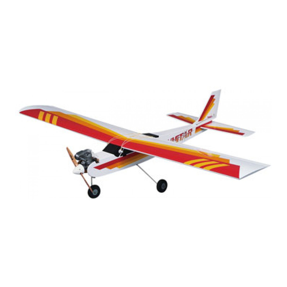
ALMOST READY-TO-FLY RADIO CONTROLLED MODEL AIRPLANE
• ALL AIRFRAME PARTS ARE FACTORY ASSEMBLED FOR PERFECT ALIGNMENT AND QUICK
ASSEMBLY.
• ALL PRE-ASSEMBLED COMPONENTS ARE FACTORY COVERED.
• CLASSIC DESIGN WITH DURABLE BALSA AND PLYWOOD CONSTRUCTION.
• SEMI-SYMMETRICAL AIRFOIL GIVES THE AVISTAR 40 PREDICTABLE FLIGHT CHARACTERISTICS.
© ENTIRE CONTENTS COPYRIGHT 1988, HOBBICO, INC.
Advertisement
Table of Contents

Related Manuals for Hobbico avistar 40


Summary of Contents for Hobbico avistar 40
- Page 1 • ALL AIRFRAME PARTS ARE FACTORY ASSEMBLED FOR PERFECT ALIGNMENT AND QUICK ASSEMBLY. • ALL PRE-ASSEMBLED COMPONENTS ARE FACTORY COVERED. • CLASSIC DESIGN WITH DURABLE BALSA AND PLYWOOD CONSTRUCTION. • SEMI-SYMMETRICAL AIRFOIL GIVES THE AVISTAR 40 PREDICTABLE FLIGHT CHARACTERISTICS. © ENTIRE CONTENTS COPYRIGHT 1988, HOBBICO, INC.
-
Page 2: Additional Items
If the Avistar 40 is not quite what you expected, return it to your dealer in New and Unused condition. However, we think you will agree with us that the Avistar 40 kit is one of the finest models of its type and will offer you many hours of enjoyment. -
Page 3: Table Of Contents
PARTS LIST Before assembly match the parts in the exploded view of the Avistar with the parts in the kit Check off each part on the parts list If any parts are missing or damaged return the kit to your hobby dealer 1 Right wing 2 Left wing 3 Fuselage... - Page 4 PRE-ASSEMBLY Locate part #6 wing joiner Join the two wing joiners together using a light coat Locate the #4 vertical stabilizer and #5 horizontal stabilizer The rudder is of epoxy They should form a "V" shape as shown above temporarily attached to the vertical stabilizer The elevator is temporarily attached to the horizontal stabilizer Remove the rudder, elevator, and metal hinges Apply a small amount of vaseline along the hinge joint on both sides of the hinge...
- Page 5 Using the same procedure tor epoxying the hinges that was used in Step 6, Remove the aileron and apply epoxy to the hinges and the part of the torque rod epoxy the three hinges into the horizontal stabilizer. Epoxy two hinges into the that is inserted into the aileron Carefully install the aileron on the hinges and vertical stabilizer torque rod Install the ailerons on both wings leaving no hinge gap...
-
Page 6: Right Wing
WING JOINER INSTALLATION When you are satisfied with the fit of the wing joiner remove the wings from the Using the wing joiner assembled in Step 1 of pre assembly insert the wing joiner joiner Mix a batch of 30 minute epoxy and using the right wing panel (has Avistar into the wing panel temporarily Also install the wing #43 alignment peg as on top) smear the inside of the right wing joiner pocket with a heavy coat of shown Do not glue at this time... -
Page 7: Fuselage
Note: You may proceed with fuselage preparation and come back to here after the wing is ready. After the epoxy has fully cured (overnight) remove the masking tape and apply Remove the servo tray and, following the picture, remove the covering from area "A". -
Page 8: Main Landing Gear
FUSELAGE PREPARATION On the side at the rear of the fuselage use your finger to locate the stabilizer cut The elevator exit hole is located on the left side of the fuselage 6" forward of the outs They will be soft spots under the covering on both sides Using a sharp tail post and approximately 1/2 inch above the bottom of the fuselage You may knife remove the covering material from the soft spots on both sides During the be able to detect this as a soft spot in the fuselage Remove the covering from... - Page 9 HORIZONTAL STABILIZER IMPORTANT: This next series of steps will determine how well your Avistar 40 will fly So please read and reread these steps so that you are totally familier with its sequence Locate the horizontal stabilizer Slide the stabilizer into the slot prepared in the...
- Page 10 INSTALLATION OF VERTICAL STABILIZER Now if we have done a good job with the wing-stabilizer relationship the installation of the rudder should be easy The vertical stabilizer needs to be at 90° to the horizontal stabilizer and the horizontal stabilizer is parallel to the wing A drafting triangle would be helpful here Using the same scrap of plywood apply an even coat of epoxy to the top and bottom of the horizontal stabilizer in the area where you removed the covering...
-
Page 11: Fuel Tank
MAIN LANDING GEAR INSTALLATION Place a small bead of silicone sealant in the groove, then insert the landing gear strut If using the Snap 'R' Keeper make a 90° bend 5/16" from the end of the into the fuselage in the holes on the bottom as shown. Secure the struts in place with 17 3/4"... -
Page 12: Engine Installation
ENGINE INSTALLATION Install the back plate of the spinner then install the prop so that when the prop If using the Snap R Keeper make a 90° bend 5/16 from the end of the 17 3/ is at 2 o'clock there is resistance from the compression of the engine Tighten the 4 control rod as shown If using the E-Z connector, install the connector on the prop nut securely and install the spinner using the two screws that came with the... -
Page 13: Fuel Pipe
RADIO INSTALLATION Using your radio switch as a guide make the necessary opening for mounting Wrap the fuel tank with natural foam to insulate it from vibration Install the fuel the switch on the left side of the fuselage as viewed from above and looking tank so that the cap is through the hole in the firewall Install two five inch pieces of fuel tubing to the fuel pipes from the fuel tank Connect the tubing from the line toward the engine and 1 1/4"... -
Page 14: Clevis
CONTROL HORN INSTALLATION Plug the servos and switch into the receiver and the receiver battery into the When installing control horns the center line of the control horn holes must be the switch Then wrap the receiver and the receiver battery in natural foam Use same as the center line of the hinge joint If not the control surface will move rubber bands to loosely hold the foam in place This foam packing protects the farther one way than the other... -
Page 15: Radio Installation
CONTROL ROD ADJUSTMENT RADIO INSTALLATION Be sure that your radio system is fully charged and the servos are plugged into If using the Snap R' Keeper mark on the push rod where the hole in the servo the receiver Turn on the transmitter then receiver Set the trim levers to the arm is neutral position Turn the receiver then the transmitter back off Adjust the servo arms so that they are positioned as shown above The screw... -
Page 16: Aileron Servo Installation
AILERON SERVO INSTALLATION Route the servo wire through the side of the tray as shown Using the screws supplied Drill a 1 /16 hole in the side of the fuselage and the upper portion of the vertical with your radio mount the servo into the tray Install the clevises on the threaded ends stabilizer Install the strain relief close to the receiver Route the receiver antenna of the aileron control rods Connect the control rods to the aileron horns Center the through the holes as shown This configuration should allow for the best radio... -
Page 17: Engine Maintenance
STARTING ENGINE Engine Maintenance Always check the engine mounting bolts muffler glow plug propeller 5 Turn the radio on and open the throttle to full open Place your and spinnner etc before attempting to start the engine Check for finger over the air intake on the carburetor while turning the loose bolts nuts or screws which may come off when the engine is prop counter clockwise a few times Notice the fuel line If any running and cause serious damage Always check the area in which... - Page 18 FLIGHT CHARACTERISTICS Pre-Flight Check Landing 1 Clean the dust dirt and oil off of the surface of the airplane There is an old saying that states You do not have to take off 2 Check to make sure all nuts, bolts and screws are securely you do have to land Therefore be ready to land at all times during your fastened flight The engine may not stay running through a complete tank of fuel...
- Page 19 A Make sure transmitter and receiver battery packs are fully charged 5 Gently advance the throttle to full power One way to check is by using a Hobbico voltmeter 6 Gently steer the Avistar left or right as necessary to obtain a...
Need help?
Do you have a question about the avistar 40 and is the answer not in the manual?
Questions and answers