Table of Contents
Advertisement
Quick Links
Download this manual
See also:
User Manual
Advertisement
Table of Contents

Related Manuals for Hobbico Avistar 40


Summary of Contents for Hobbico Avistar 40
- Page 1 Entire Contents © Copyright, 1995 HCAZ3005 V 1.0...
-
Page 2: Tail Assembly
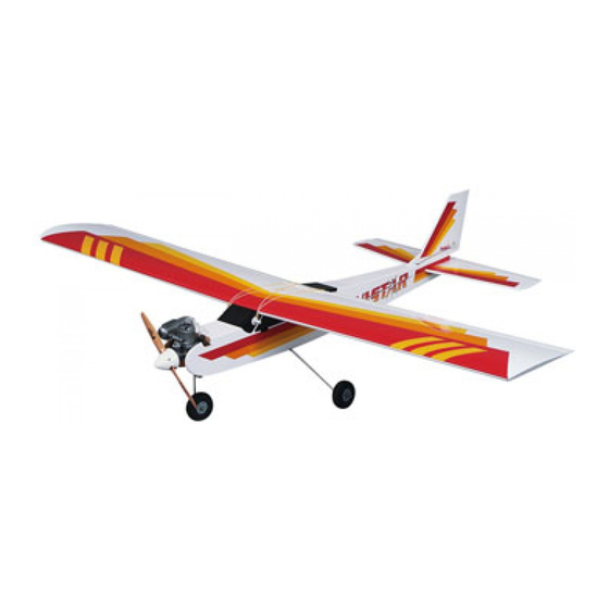
-hank you for purchasing the Hobbico Avistar ARF! This all Tail Assembly wood sport/trainer can be ready to fly in a fraction of the time Part# Quantity it would take to build a conventional wood kit. It features a Horizontal stab and elevator..I semi-symmetrical airfoil for a good combination of acrobatic Vertical fin and rudder....1... -
Page 3: Landing Gear
Landing Gear Fuel Tank & Parts Part# Quantity Part# Quantity Main landing gear struts ...2 Fuel tank..........1 Nose gear strut ......1 Rubber tank stopper......1 Plastic Steering Arm....1 Fuel pick-up weight (clunk) ....1 Landing gear straps ....2 Plastic stopper disks Wheels........2 (one large and one small) ....2 Wheel collars w/ set screws ..4... -
Page 4: Radio Equipment
Glues Choose a high quality 6-minutc and 30-minute epoxy, such as Great Planes Pro Epoxy, w h i c h has been formulated especially for R / C model building. Pro Epoxies offer a strong bond and a variety of curing times suited for every step of assembly. -
Page 5: Before You Fly
n a t i o n a l o r g a n i z a t i o n w i t h f you're a beginner, the best way to begin flying your Avistar is with more t h a n 2,300 c h a r t e r e d c l u b s across the c o u n t r y . -
Page 6: Special Note
Special Note: both sides of one of the wing joiners. Sandwich this coated joiner between the remaining two. Quickly You should charge your radio system before starting proceed through the following steps (3 and 4) before to build. Following the manufacturer's directions, the glue cures. - Page 7 Mark the centerline on the joiner Trial fit the wing joiner Q 8. Trial Fit the wing joiner in both wing panels by 5. After the epoxy has cured and the clothespins sliding the joiner into the joiner cavity in the wing. have been removed, draw a centerline on both The joiner should slide in with little resistance up to sides of the plywood wing joiners and the two balsa...
-
Page 8: Join The Wing Halves
outside of the wing using a paper towel dampened Please read through the following three steps before with rubbing alcohol. Use several strips of masking mixing any epoxy. You must complete these steps tape on both sides to hold the wing halves tightly within 20 minutes from the time you mix the epoxy. -
Page 9: Install The Servo Tray
Assemble the servo tray equal amounts of epoxy to the mounting blocks on both ends of the servo tray. Attach the servo tray to the bottom of the wing with the servo wire harness notch facing the leading edge of the wing. Allow the epoxy to fully cure before proceeding to the next step. -
Page 10: Install The Aileron Control Horns
Install the aileron control horns Securing the aileron pushrods 1-1 23. Locate the 1 / 4 " ( 6 . 5 m m ) d i a m e t e r clear retaining tube and cut two 1/4" (6.5mm) pieces. Slide _1 20. -
Page 11: Install The Wing Dowels
Locate the stabilizer slot Locate the wing dowel holes Q 3. Locate the horizontal stabilizer slot under the covering on the tail section of the fuselage by pressing lightly with your finger. The slot is located on both sides of the tail. Using a hobby knife, carefully remove 1. - Page 12 them as described here: First, flex the surface all the Remove the tail post way one direction (DO NOT REMOVE THE SURFACE). Apply 5 drops of thin CA onto each hinge. Use a paper towel to absorb the excess glue. Wait a few minutes for the glue to harden, then flex the surface the other direction and glue the other side of the hinges.
-
Page 13: Install The Stabilizer
Align the stabilizer with the fuse drawn in the last step. Next, carefully cut through the covering using a new #11 knife blade at the inside T-PIN lines and remove the covering from the center. Do not cut the wood under the covering! This would seriously weaken the stabilizer and could easily cause the stabilizer to break in flight. -
Page 14: Dorsal Fin
Apply the decaf to the dorsal fin Attaching the rudder control horn 1-1 19. Position a c o n t r o l horn as shown in the previous sketch, 7/8" (22 mm) from the bottom of the rudder. Mark the two holes with a felt tip pen. Angle the horn slightly so it is straight with the fuselage. - Page 15 Cut the rudder pushrod exit Prepare the channel for the gear J 25. Trial fit the chrome wire landing gear struts 22. The pre-cut rudder pushrod exit hole is located into the holes. It they will not go in easily, drill out the on top of the fuselage on the same side as the rudder two holes using an 11/64"...
-
Page 16: Engine Selection
D 33. Make a Z-bend at one end of both of the 1/16" x 18" wire pushrods using needle nose pliers. NOTE: Hobbico offers pliers that easily make perfect Z-bends (HCAR2000). See your hobby dealer. Q 30. Using sandpaper, roughen the outside of both plastic guide tubes and clean with a paper towel dampened with rubbing alcohol. - Page 17 Install the steering pushrod Assemble the fuel tank plug Q 38. Push one long and one short aluminum tube through the black r u b b e r stopper - the third aluminum tube will not be used. Place the two white plastic disks over the tubes.
-
Page 18: Install The Tank
Install the stopper Drill the hatch Front 41. The stopper assembly can now be inserted into Q 44. Drill four 1/16" holes into the tank hatch as the tank. The pressure tube should be adjusted so the shown in the sketch. tube is pointed straight up just under the top of the tank. -
Page 19: Drill Mounting Holes
Drill mounting holes Attach the propeller to the engine 1-1 47. Remove the engine from the mount and drill four 1 /8" holes at the marks you just made. Attach fuel tubing to the tank LI 48. Cut two 6" pieces of medium silicone fuel tubing (not included). -
Page 20: Install The Aileron Servo
Install the servo tray support Note: When installing a 4-stroke engine, the throttle servo should be installed in the opposite direction. Choose and trim the servo arms so they look similar to the ones shown in the photo. Install the aileron servo Q 55. -
Page 21: Clevises
Mount the switch to the fuselage Make the clevis retainers -I 63. Cut two 1 /4" wide pieces of the clear tube. Slide one on each of the pushrods that protrude out of the fuselage. Install the two clevises J 60. Cut out the opening on the left side of the fuselage for the switch and install using the screws included with the switch. -
Page 22: Connect The Pushrods
Mark the pushrods Attach the pushrod connector Q 70. Install a pushrod connector on the opposite side of the r u d d e r p u s h r o d . This w i l l be for the steering pushrod. -
Page 23: Install The Pushrods
Make the clevis retainers Mount the switch to the fuselage LJ 63. Cut two 1 /4" wide pieces of the clear tube. Slide one on each of the pushrods that protrude out of the fuselage. Install the two clevises -1 60. Cut out the opening on the left side of the fuselage for the switch and install using the screws included with the switch. - Page 24 Mark the pushrods Attach the pushrod connector Q 70. Install a pushrod connector on the opposite side of the rudder p u s h r o d . This will be for the steering pushrod. Thread the nut onto the connector. The connector must be able to rotate in the servo arm, so do not over-tighten the nut.
-
Page 25: Install The Wheels
Connect the aileron servo Install the wheels Q 73. Hold the ailerons at neutral and mark the servo wheel where the rods intersect the holes in the servo arm. Make a "Z" bend at the marks and attach to the servo arms. -
Page 26: Check The Control Directions
Check The Control Directions connector. The throw w i l l be correct when the carburetor barrel will stop fully open at the same time 1. Turn on t h e T r a n s m i t t e r and then the Receiver. the throttle stick reaches full. -
Page 27: Check The Lateral Balance
weight to the nose. If the nose drops, the plane is Important: "nose heavy" and you must add weight to the tail. If possible, first a t t e m p t to balance the model by This section is VERY important and must not be changing the position of the battery and receiver. -
Page 28: Charge The Batteries
If you're a novice, there is one thing that you will fuel to foam, which will, in turn, cause your engine to need to fly your Avistar II safely that is not furnished run rough or quit. with the kit: You will need a qualified instructor to teach you to fly. -
Page 29: Ama Safety Code
RANGE CHECK YOUR RADIO AMA SAFETY CODE Check the operation of the radio every time you fly. This means that with the t r a n s m i t t e r antenna Read and abide by the Academy of Model Aeronautics collapsed and the receiver and transmitter on, you Official Safety Code, a portion of which is reprinted should he able to walk at least 100 feet away from the... - Page 30 Your first flights should consist of mostly It is best if you let the instructor test fly the model straight and level flight with gentle turns to keep the first. Once he has flown the model he will adjust the model over the field.
- Page 31 YawAxis Wing Tip Aileron Pitch Axis Hinges Vertical Fin Roll Axis Trailing Edge Aileron Rudder Leading Torque Rods Control Horns Edge Hinges (on all control Propeller surfaces) Engine Muffler Elevator Fuel Tank Stabilizer Servos Fuselage Pushrods Receiver Battery Spinner Receiver Switch Harness Antenna Receiver...
- Page 32 to depart from the aircraft and cause Expanded Scale Voltmeter (ESV) - can be programmed completely to a crash. There are many reasons for fine tune an airplane without mak- Device used to read the battery volt- this but the most common are exces- ing mechanical changes.
- Page 33 Glow Plug Clip/Battery - A 1.2 volt Muffler - A device attached to the at each wingtip. Raising or lowering battery', which is connected to the exhaust stack of the engine to the nose is the pitch movement. glow plug on a model airplane reduce noise, and increase back This is how the climb or dive pressure which helps low speed...
- Page 34 Wing Loading - This is the amount alogthewing trailing edge and does the physical work inside of weight per square foot that has bent down to connect to the the airplane. to be overcome to provide lift. It is aileron servo push rods. normally expressed in ounces per Servo Output Ann - The removable Trailing Edge (TE) - I he very aft...
Need help?
Do you have a question about the Avistar 40 and is the answer not in the manual?
Questions and answers