Table of Contents
Advertisement
Quick Links
Advertisement
Table of Contents

Related Manuals for Black Horce Model JU87-STUKA BH80


Summary of Contents for Black Horce Model JU87-STUKA BH80
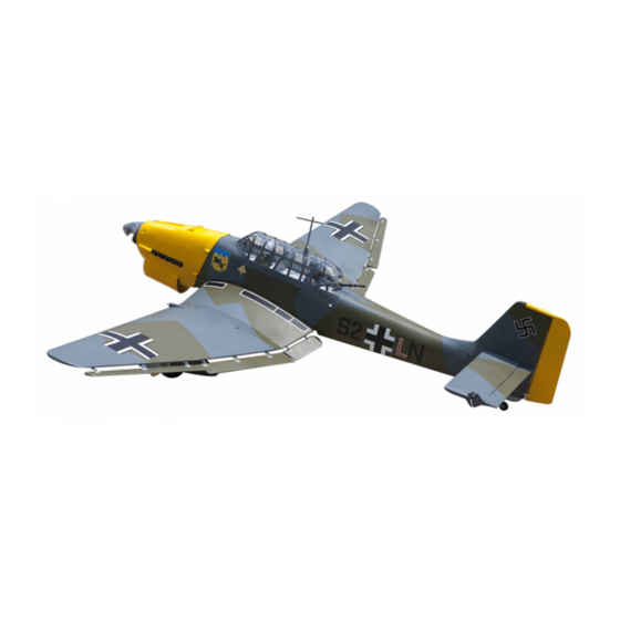
- Page 1 Instruction Manual book SPECIFICATION Wingspan : 1,920 mm 75.59 in. Length 1,560 mm 61.42 in. Weight 5 kg 11.00Lbs. Radio 06 channels.
- Page 2 JU87-STUKA - Instruction Manual Item code: BH80 This instruction manual is designed to help you build a great flying aeroplane. Please read this manual thoroughly before starting assembly of your JU87-STUKA. Use the parts listing below to identify all parts. WARNING.
-
Page 3: Safety Precaution
JU87-STUKA - Instruction Manual Item code: BH80 SAFETY PRECAUTION. + This is not a toy + Be sure that no other flyers are using your radio frequency. + Do not smoke near fuel + Store fuel in a cool, dry place, away from children and pets. - Page 4 JU87-STUKA - Instruction Manual Item code: BH80 Bottom side 2) Using a modeling knife, remove the cov- ering at possition show below. Remove 2x10mm. covering Secure Bottom side Secure 2.INSTALLING THE AILERON CON- TROL HORN. 3) Using the thread as a guide and using Nilon control clasp masking tape, tape the servo lead to the end of the thread: carefully pull the thread out.
-
Page 5: Installing The Aileron Linkages
JU87-STUKA - Instruction Manual Item code: BH80 3.INSTALLING THE AILERON LINKAGES. Installing the aileron linkages as pictures below. 115mm M2 lock nut Repeat the procedure for the other wing half. C/A glue. 1.1. INSTALLING THE FLAP 1 SERVOS. Thread... - Page 6 JU87-STUKA - Instruction Manual Item code: BH80 Electric wire. Secure Bottom side 2.2.INSTALLING THE FLAP 1 CONTROL HORN . Nilon control clasp Flap control horn. 3mm x 40mm. M3 lock nut. 2.3. INSTALLING THE FLAP1 LINKAGES. Installing the flap1 linkages as pictures below.
- Page 7 JU87-STUKA - Instruction Manual Item code: BH80 Repeat the procedure for the other wing half. 3.1.INSTALLING THE FLAP 2 SERVOS . 3.2.INSTALLING THE FLAP 2 CONTROL HORN. Nilon control clasp M3 lock nut. 3mm x 40mm. 3.3. INSTALLING THE FLAP2 LINKAGES.
- Page 8 JU87-STUKA - Instruction Manual Item code: BH80 3 x 12mm Flap1 Flap2 Repeat the procedure for the other wing Drill 2mm half. hole MAIN GEAR INSTALATION. PARTS REQUIRED 3x15mm 3x15mm 3 x 12mm 3 x 10mm 3 x 10mm Secure...
- Page 9 JU87-STUKA - Instruction Manual Item code: BH80 Plastic fairing for landing gear. Drill 2mm hole 3 x 15mm Secure...
- Page 10 JU87-STUKA - Instruction Manual Item code: BH80 Secure Secure Secure...
- Page 11 JU87-STUKA - Instruction Manual Item code: BH80 Secure C/A glue Plastic bomb2. 3x10mm. Drill a hole 2mm diameter C/A glue Drill a hole 2mm diameter...
- Page 12 JU87-STUKA - Instruction Manual Item code: BH80 C/A glue Repeat the procedure for the other wing half. Epoxy glue. FUSELAGE TOP HATCH...
- Page 13 JU87-STUKA - Instruction Manual Item code: BH80 C/A glue C/A glue Epoxy glue. C/A glue C/A glue...
-
Page 14: Installing The Engine Mount
JU87-STUKA - Instruction Manual Item code: BH80 INSTALLING THE ENGINE MOUNT. See pictures below: 4x 30mm 4x 30mm FUEL TANK. INSTALLING THE STOPPER ASSEMBLY 1. The stopper has been pre-assembled at the factory. silicon not included. 2. Using a modeling knife, cut one length of silicon fuel line (the length of silicon fuel line is calculated by how the weighted clunk should rest about 8mm away from the rear of the tank... - Page 15 JU87-STUKA - Instruction Manual Item code: BH80 Fuel pick- up tube Vent tube Fuel fill tube 5. Test fit the stopper assembly into the tank. It may be necessary to remove some of 9. To secure the fuel tank in place, apply a the flashing around the tank opening using bead of silicon sealer to the forward area of a modeling knife.
-
Page 16: Installing The Engine
JU87-STUKA - Instruction Manual Item code: BH80 Drill a hole 4mm diameter. INSTALLING THE ENGINE. Locate the long piece of wire used for the 4 x 30mm throttle pushrod. One end of the wire has been pre-bend in to a “Z” bend at the factory. This “Z”... - Page 17 JU87-STUKA - Instruction Manual Item code: BH80 Right side Pushrod wire Trim and cut after. COWLING. 1. Slide the fiberglass cowl over the en- gine and line up the back edge of the cowl with the marks you made on the fuselage. Left side ...
-
Page 18: Installing The Spinner
JU87-STUKA - Instruction Manual Item code: BH80 Secure Front view INSTALLING THE THROTTLE PUSHROD. INSTALLING THE SPINNER. 1. Install one adjustable metal connector Install the spinner backplate, propeller and through the third hole out from the center of spinner cone. The spinner cone is held in one servo arm, enlarge the hole in the servo place using two 3mm x 12mm wood screws. -
Page 19: Horizontal Stabilizer
JU87-STUKA - Instruction Manual Item code: BH80 HORIZONTAL STABILIZER. See pictures below: Secure ELEVATOR INSTALLATION. SERVO INSTALLATION. 1. Install the rubber grommets and brass collets into the elevator servo. Test fit the servo into the servo tray. 2. Mount the servo to the tray using the mounting screws provided with your radio sys- tem. - Page 20 JU87-STUKA - Instruction Manual Item code: BH80 C/A glue C/A glue C/A glue C/A glue...
- Page 21 JU87-STUKA - Instruction Manual Item code: BH80 Center line C/A glue 2 Using a modeling knife, cut away the covering from the fuselage for the stabilizer and remove it. C/A glue Remove covering. C/A glue 3. Mark the shape of the vertical on the left and right sides onto the horizontal stabilizer using a felt-tip pen C/A glue...
-
Page 22: Horizontal Stabilizer Struts
JU87-STUKA - Instruction Manual Item code: BH80 4. Remove the stabilizer. Using the lines you just drew as a guide, carefully remove the C/A glue covering from between them using a modeling knife. When cutting through the covering to remove it, cut with only enough pres- sure to only cut through the covering it’s self. - Page 23 JU87-STUKA - Instruction Manual Item code: BH80 6. After the epoxy has fully cured, remove the masking tape or T-pins used to hold the stabilizer in place and carefully inspect the glue joints. Use more epoxy to fill in any C/A glue gaps that were not filled previously and clean up the excess using a paper towel and...
- Page 24 JU87-STUKA - Instruction Manual Item code: BH80 ELEVATOR AND RUDDER PUSHROD INSTALLATION. Elevator and rudder pushrod install as same as the way of aileron pushrod. M2 lock nut. Elevator pushrod Elevator Elevator pushrod pushrod Elevator pushrod Elevator E l e v a t o r E l e v a t o r control horn.
-
Page 25: Vertical Installation
JU87-STUKA - Instruction Manual Item code: BH80 Secure Secure Throttle pushrod. Secure VERTICAL INSTALLATION. Rudder servo install as same as method of elevator servo. See picture below: Bend and cut. C/A glue... - Page 26 JU87-STUKA - Instruction Manual Item code: BH80 Remove covering. C/A glue 2. Put the rudder into the fuselage as same as picture below. 3. Mark the shape of the vertical on the left and right side on the rudder using a felt-tip pen.
- Page 27 JU87-STUKA - Instruction Manual Item code: BH80 5. Put the vertical stabilizer back in place. Using a triangle, check to ensure that the vertical stabilizer is aligned 90 de- gree to the horizontal stabilizer. C/A glue Hinge slot Epoxy glue C/A glue ...
-
Page 28: Rudder Control Horn Installa- Tion
JU87-STUKA - Instruction Manual Item code: BH80 RUDDER CONTROL HORN INSTALLA- TION. Rudder control horn install as same as the way of aileron control horn. Please see pic- tures below. M3 lock nut. Nilon control clasp 3mm x 60mm. Control horn of Rudder. Elevator Elevator pushrod... - Page 29 JU87-STUKA - Instruction Manual Item code: BH80 2. Using a pen, mark the locations of the two mounting screws. Remove the tail wheel bracket and drill 1mm pilot holes at the loca- tions marked. C/A glue ...
-
Page 30: Installing The Switch
JU87-STUKA - Instruction Manual Item code: BH80 Elevator Elevator pushrod pushrod Rudder Rudder pushrod. pushrod. C/A glue INSTALLING THE SWITCH. 1. Cut out the switch hole using a modeling knife. Use a 2mm drill bit and drill out the two mounting holes through the fuse- lage side. -
Page 31: Wing Attachment
JU87-STUKA - Instruction Manual Item code: BH80 switch INSTALLING THE RECEIVER AND BATTERY. 1. Plug the servo leads and the switch lead into the receiver. You may want to plug an aileron extension into the receiver to make plugging in the aileron servo lead easier when you are installing the wing . - Page 32 JU87-STUKA - Instruction Manual Item code: BH80 Top side Wing bolt Drill a hole 3mm diameter 4 x 30mm Top side Secure WING ATTACHMENT. See picture wing attach to fuselage. Drill a hole Wing bolt. 3mm diameter Installing the fuselage hatch as same as pic- ture below.
- Page 33 JU87-STUKA - Instruction Manual Item code: BH80 Secure C/A glue...
- Page 34 JU87-STUKA - Instruction Manual Item code: BH80 Mark point. C/A glue C/A glue C/A glue...
- Page 35 JU87-STUKA - Instruction Manual Item code: BH80 C/A glue C/A glue C/A glue BALANCING. 1) It is critical that your airplane be bal- anced correctly. Improper balance will cause your plane to lose control and crash. THE CENTER OF GRAVITY IS LOCATED 100MM BACK FROM THE LEADING EDGE OF THE WING.
-
Page 36: Pre-Flight Check
JU87-STUKA - Instruction Manual Item code: BH80 With the wing attached to the fuselage, all parts of the model installed ( ready to fly), and 12mm empty fuel tanks, hold the model at the 12mm marked balance point with the stabilizer level. Lift the model.
Need help?
Do you have a question about the JU87-STUKA BH80 and is the answer not in the manual?
Questions and answers