Table of Contents
Advertisement
Advertisement
Table of Contents

Subscribe to Our Youtube Channel
Related Manuals for Atlas Copco CR Series


Summary of Contents for Atlas Copco CR Series
- Page 1 Atlas Copco Industrial cast iron piston compressors CR Range Instruction book...
- Page 3 Atlas Copco Industrial cast iron piston compressors CR Range Instruction book Original instructions Copyright Notice Any unauthorized use or copying of the contents or any part thereof is prohibited. This applies in particular to trademarks, model denominations, part numbers and drawings.
-
Page 4: Table Of Contents
Instruction book Table of contents Table of contents .......................... 2 Safety precautions ......................... 4 Safety icons ............................4 Safety precautions, general ......................4 Safety precautions during installation ....................4 Safety precautions during operation ....................6 Safety precautions during maintenance or repair ................7 General description ........................ - Page 5 Instruction book Lubrication of compressors ......................39 Service kits ............................. 39 Disposal of used material ....................... 39 Servicing and adjustment procedures ................40 Air filter ............................40 Adjustment of MDR4 pressure switch ..................... 40 Adjustment of MDR3 pressure switch ..................... 41 Adjustment of pilot valve .........................
-
Page 6: Safety Precautions
Instruction book Safety precautions Safety icons Explanation Danger for life Warning Important note Safety precautions, general General precautions 1. The operator must employ safe working practices and observe all related work safety requirements and regulations. 2. If any of the following statements does not comply with the applicable legislation, the stricter of the two shall apply. - Page 7 Instruction book Precautions during installation 1. The machine must only be lifted using suitable equipment in accordance with the applicable safety regulations. Loose or pivoting parts must be securely fastened before lifting. It is strictly forbidden to dwell or stay in the risk zone under a lifted load. Lifting acceleration and deceleration must be kept within safe limits.
-
Page 8: Safety Precautions During Operation
Instruction book Safety precautions during operation All responsibility for any damage or injury resulting from neglecting these precautions, or non-observance of the normal precautions and care required for installation, operation, maintenance and repair, even if not expressly stated, will be disclaimed by the manufacturer. -
Page 9: Safety Precautions During Maintenance Or Repair
Instruction book Safety precautions during maintenance or repair All responsibility for any damage or injury resulting from neglecting these precautions, or non-observance of the normal precautions and care required for installation, operation, maintenance and repair, even if not expressly stated, will be disclaimed by the manufacturer. - Page 10 Instruction book Also consult the following safety precautions: Safety precautions during installation and Safety precautions during operation. These precautions apply to machinery processing or consuming air or inert gas. Processing of any other gas requires additional safety precautions typical to the application which are not included herein.
-
Page 11: General Description
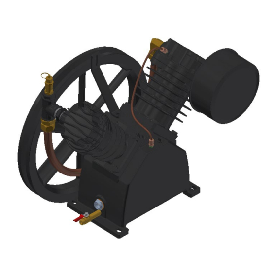
Instruction book General description General description Introduction CR Range Compressors are air-cooled, two cylinder, single-stage and double-stage, lubricated piston compressors, built for effective working pressures up to 145-175 psi. Compressor block Compressor block Reference Description Cylinder Crankcase Oil drain Intercooler Cylinder head Pressure relief valve 2022 2096 26... - Page 12 Instruction book Tank-mounted, vertical receiver Tank-mounted, vertical receiver Reference Description Compressor Filter Air pressure switch Air receiver Air pressure gauge Crankcase Intercooler Pressure relief valve Air outlet valve Control panel 2022 2096 26...
- Page 13 Instruction book Tank-mounted, vertical receiver Tank-mounted, horizontal receiver Reference Description Compressor Pressure relief valve Air outlet valve Hour meter (option) Electric cabinet On/off switch Air receiver Air pressure switch Air pressure gauge Compressor Condensate drain valve 2022 2096 26...
-
Page 14: Hour Meter Option
Instruction book Compressor variants The compressor block includes: • Crankcase and cylinders • Air cooler piping • Check valve • Pressure relief valve The unit comprises: • Tank-mounted CR with electric motor: The compressor on a horizontal or vertical air receiver with air outlet valve, pressure gauge, pressure relief valve, air pressure switch with an on/off button (MDR), and condensate drain valve. - Page 15 Instruction book Specifications Display Reading: 9999.9 Hour meter Digit Height: 5-digits [8MM] LCD Operating Voltage: Internal lithium battery 15,000 hours continuous running Temperature: Standard -40°C to +85°C (-40°F to +185°F) Vibration Resistance: Withstands 10 to 75Hz @ 1 to 8 g’s Mounting Configuration: Two hole base mount 2022 2096 26...
-
Page 16: Control Piping
Instruction book Control piping CR 2 to 15 hp Air drawn through the air filter and inlet silencer into cylinders is compressed, then discharged through the cooler piping and “and check valve / unloader valve” into the air receiver. From compressor discharge Control piping and regulating system with automatic start/stop... - Page 17 Instruction book From compressor discharge Used on CR-15 units only. Control piping and regulating system with load/unload Reference Description Pressure relief valve Air receiver Discharge line check valve Vent Pressure gauge Pilot valve Flow to head unloaders Flow from compressor interstage Electronic drain Vent to atmosphere 2022 2096 26...
- Page 18 Instruction book From compressor discharge Used on CR-15 units only. Control piping and regulating system with dual control and pilot Reference Description Pressure relief valve Air receiver Discharge line check valve Vent Pressure switch Pressure release valve on pressure switch Pressure gauge Pilot valve Flow to head unloaders...
- Page 19 Instruction book Control piping and regulating system, duplex tank mount with automatic start/stop Reference Description Control panel Pressure transducer Pressure gauge Air receiver 3-way normally-open solenoid valve Vent Pressure relief valve Compressor Discharge line 2022 2096 26...
- Page 20 Instruction book Control piping and regulating system, duplex tank mount with dual control and solenoid valve Reference Description Control panel Pressure transducer Pressure gauge Air receiver Vent Pressure relief valve Flow from interstage Interstage dump valve (Used on CR-15 units only.) Flow to compressor head unloaders Discharge line Compressor...
-
Page 21: Regulating System
Instruction book Regulating system Automatic Start/Stop The regulating system includes: • Check valve • Air pressure switch (MDR) with pressure release valve and on/off button (S1). Operation The air pressure switch opens and closes its contacts at pre-set pressures. During loaded operation, the contacts are closed: the motor is running. -
Page 22: Installation
Instruction book Installation Installation instruction Install the unit in an area where the noise levels do not cause inconvenience and adequate ventilation is available for cooling purposes. Before commencing installation, check that the electrical data on the compressor specification plate/s are compatible with the local power supply. Before connecting the electricity, ensure that the power supply is off and correctly isolated. - Page 23 Instruction book Installation proposal for CR with horizontal receiver 2022 2096 26...
-
Page 24: Electrical Connections
Instruction book Install the compressor horizontally, in a cool but frost-free and well-ventilated room. Place the compressor as level as possible; however, CR can be operated with a maximum inclination of 40% (22.5 degrees) in any direction. The air should be clean. It is recommended to install an automatic condensate drain (available as an option) on the air receiver to ensure continuous condensate removal. - Page 25 Instruction book Fig. 3-1 2022 2096 26...
- Page 26 Instruction book Fig. 3-2 2022 2096 26...
- Page 27 Instruction book Fig. 3-3 2022 2096 26...
- Page 28 Instruction book Fig. 3-4 2022 2096 26...
- Page 29 Instruction book Fig. 3-5 2022 2096 26...
- Page 30 Instruction book Fig. 3-6 2022 2096 26...
- Page 31 Instruction book Fig. 3-7 2022 2096 26...
- Page 32 Instruction book Fig. 3-8 2022 2096 26...
- Page 33 Instruction book Fig. 3-9 2022 2096 26...
- Page 34 Instruction book Fig. 3-10 2022 2096 26...
- Page 35 Instruction book Fig. 3-11 2022 2096 26...
-
Page 36: Fuses And Wire Sizes
Instruction book Fuses and wire sizes Values shown here have been determined using National Electrical Code (NFPA 70). Local electrical code requirements my differ. Refer to your local electrical code. Fuses (Dual Element Volts Single Phase Volts Three Phase Time-Delay) Wire Size (minimum) CR_5... -
Page 37: Operating Instructions
Instruction book Operating instructions Initial start-up If the compressor has not run for the past 6 months (at initial start-up check the date on the data plate), it is strongly recommended to improve the lubrication of the compressor element: drain the oil, refill the compressor with the same oil while turning the crankshaft. - Page 38 Instruction book CR Contractor with electrical motor 1. Check the oil level, which must be near the top of the red circle of the sight-glass. The minimum level is the lower part of the red circle. 2. Set the pilot valve in the unload position by turning the red handle 90 degrees. Refer to Adjustment of pilot valve.
-
Page 39: Stopping
• Store the machine in its normal position, not upside down or on its side. • If the machine is stored for 1 year or more, rotate the bearings once a month to change the position of the roller balls in the bearings. Consult Atlas Copco Service. 2022 2096 26... -
Page 40: Maintenance
Instruction book Maintenance Gas engine maintenance Consult the engine “Owner’s manual”. Preventive maintenance schedule The schedule contains a summary of the maintenance instructions. Read the respective section before taking maintenance measures. When servicing, replace all disengaged packing components, e.g. gaskets, O-rings, washers. -
Page 41: Lubrication Of Compressors
Instruction book Lubrication of compressors It is strongly recommended to use the Piston Fluid compressor oil to keep the compressor in excellent operating condition. Traditional lubricants cannot cope with the extreme conditions of piston compressors, resulting in fast oil degradation, overheating and potentially irreversible damage and high repair costs. Therefore, high performing lubricants increase the equipment lifetime. -
Page 42: Servicing And Adjustment Procedures
Instruction book Servicing and adjustment procedures Warning Release the pressure from the compressor before starting repair or maintenance works. Switch off the voltage and isolate the compressor from the mains. Air filter To replace the air filter, follow these steps: 1. -
Page 43: Adjustment Of Mdr3 Pressure Switch
Instruction book Adjustment • Adjust the air pressure switch while it is pressurized. • Switch off the voltage before removing the cover of the switch; reinstall it after an adjustment has been made and before the voltage is switched on again. The maximum pressure is controlled by adjusting screw (4). -
Page 44: Adjustment Of Pilot Valve
Instruction book Adjustment • Adjust the air pressure switch while it is pressurized. • Switch off the voltage before removing the cover of the switch; reinstall it after an adjustment has been made and before the voltage is switched on again. The stopping pressure is controlled by adjusting screw (2). -
Page 45: Pressure Relief Valve
Instruction book Unload mechanism The pilot valve is equipped with a hand-operated unload mechanism: by turning the red handle (1) 90 degrees, the plunger of the valve will be lifted, releasing the spring force. The air pressure from the pulsation dampers will force down unloader plunger (8) and the compressor will run unloaded. By turning handle (1) 90 degrees further, the plunger returns to its original position so that the pilot valve will again unload and load the compressor at the pre-set pressures. -
Page 46: Problem Solving
Instruction book Problem solving Condition Fault Low discharge pressure Restricted inlet Defective compressor valves or valve unloading mechanism Leaks in the compressed air distribution system at fittings, connections, etc. Unloader pilot valve defective or set wrong Pressure switch defective or set wrong Drive belt slipping Incorrect speed Worn piston rings or loose piston... - Page 47 Instruction book Condition Fault Low oil pressure Oil sump strainer plugged Excessive leakage at crankshaft seals Low oil level Oil pump incorrectly assembled to the bearing carrier (“o” ring not properly located between oil pump body & bearing carrier) Oil pressure adjusting screw not set properly Defective oil pressure gauge Compressor loads and Air receiver too small...
- Page 48 Instruction book Condition Fault High discharge temperature Compressor valve assemblies defective Discharge pressure too high Inadequate ventilation or hot air recirculating Cooling surfaces of compressor or intercooler excessively dirty Ambient temperature too high Scored or excessively worn cylinder walls Compressor knocks Head clearance insufficient Piston loose in cylinder bore, cylinder bore worn, piston or piston rings worn Worn rods or main bearing...
-
Page 49: Technical Data
Instruction book Technical data Reference conditions Inlet pressure (absolute) 14.5 Relative air humidity Air inlet temperature ºF Working pressure: 145-175* 145 psi for single stage units, 175 for two-stage units Limitations Minimum inlet temperature °F Maximum inlet temperature ºF Maximum working pressure See below Only applicable for Full Feature variants. -
Page 50: Instructions For Use
Instruction book Instructions for use Air receiver (tank-mounted units) Corrosion must be prevented: depending on the conditions of use, condensate may accumulate inside the tank and must be drained every day. This may be done manually, by opening the drain valve, or by means of the automatic drain, if fitted to the tank. Nevertheless, a weekly check of correct functioning of the automatic valve is needed. - Page 51 ENVIRONMENTAL AND OSHA REQUIREMENTS: At the time of Seller shall in no event be liable for delays caused by fires, acts of God, shipment of the equipment from the factory, Atlas Copco will comply with strikes, labor difficulties, acts of governmental or military authorities,...
- Page 52 Instruction book 2022 2096 26...
- Page 53 Atlas Copco’s pursuit of innovation never ceases, driven by our need for reliability and efficiency. Always working with you, we are committed to providing you the customized quality air solution that is the driving force behind your business.
Need help?
Do you have a question about the CR Series and is the answer not in the manual?
Questions and answers