
Related Manuals for Atlas Copco E-AIR 250


Summary of Contents for Atlas Copco E-AIR 250
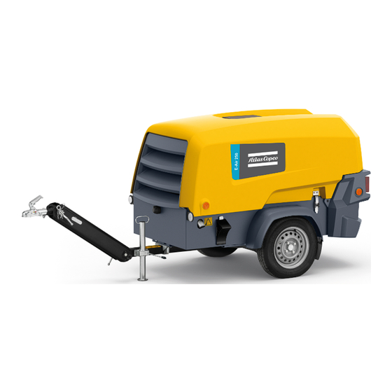
- Page 1 Instruction Manual Instruction Manual for Portable Compressors English E-AIR 250 APP...
- Page 3 Instruction Manual for Portable Compressors E-AIR 250 Original instructions Printed matter N° 2960 1160 00 ATLAS COPCO - PORTABLE ENERGY DIVISION www.atlascopco.com 09/2017...
- Page 4 Copco does not assume responsibility for possible errors. Copyright 2017, Atlas Copco Airpower n.v., Antwerp, Belgium. Any unauthorized use or copying of the contents or any part thereof is prohibited. This applies in particular to trademarks, model denominations, part numbers and drawings.
-
Page 5: Table Of Contents
Table of contents Preface Follow the instructions in this booklet and we guarantee you years of troublefree operation. It is a Safety precautions ........7 4.4.1 Control panel ......... 29 solid, safe and reliable machine, built according to 4.4.2 Overview icons ........30 Introduction .......... - Page 6 Problem solving ........47 Technical specifications ......49 Torque values ..........49 Compressor/Motor specifications ..... 50 7.31 Performance data ........51 7.32 Design data ..........54 Dimensions..........55 Data plate ..........59 Disposal............60 Maintenance Log ........61 Documents ..........65 - 6 -...
-
Page 7: Safety Precautions
To be read attentively and acted accordingly before towing, lifting, operating, performing maintenance or repairing the unit. INTRODUCTION The policy of Atlas Copco is to provide the users of It is the responsibility of management to appoint Take necessary steps to keep unauthorized persons... -
Page 8: General Safety Precautions
The manufacturer does not accept any liability for any Care shall be taken to avoid damage to safety GENERAL SAFETY PRECAUTIONS damage arising from the use of non-original parts and valves other pressure-relief devices, The owner is responsible for maintaining the unit for modifications, additions or conversions made especially to avoid plugging by paint, oil coke or in a safe operating condition. -
Page 9: Safety During Transport And Installation
- check that the wheels are secure and that the Lifting hooks, eyes, shackles, etc., shall never be SAFETY DURING TRANSPORT AND tyres are in good condition and inflated bent and shall only have stress in line with their INSTALLATION correctly, design load axis. -
Page 10: Safety During Use And Operation
8 Before removing the oil filler plug, ensure that the - above 95 dB(A): the warning(s) at the SAFETY DURING USE AND OPERATION pressure is released by opening an air outlet entrance(s) shall be completed with the valve. recommendation that also occasional visitors When operating in a dust-laden atmosphere, place shall wear ear protectors, the unit so that dust is not carried towards it by the... -
Page 11: Safety During Maintenance And Repair
26 Periodically check the cables. Damaged cables 18 Safety shoes should be compulsory in any SAFETY DURING MAINTENANCE AND workshop and if there is a risk, however small, of REPAIR and poor lighting of connections may cause electric falling objects, wearing of a safety helmet should shocks. -
Page 12: Tool Applications Safety
Atlas Copco or the cartridge is used and that its useful service life is machine manufacturer. Ascertain that the not surpassed. selected lubricants comply with all applicable... -
Page 13: Specific Safety Precautions
- capacity of the vessel V in l (US gal). If the set pressure must be altered then use only correct parts supplied by Atlas Copco and in The pressure vessel is only to be used for the accordance with the instructions available for the applications as specified above and in accordance valve type. -
Page 14: Leading Particulars
Leading particulars DESCRIPTION OF SAFETY PICTOGRAMS USED IN THIS MANUAL This symbol draws your attention dangerous situations. operation concerned may endanger persons and cause injuries. This symbol followed supplementary information. GENERAL DESCRIPTION The compressors type E-Air250 is a silenced, single- stage, oil-injected screw compressors, built for a nominal effective working pressure of 7 bar (102 psi) to 14 bar (200 psi) (see chapter Technical... - Page 15 Regulation Frequency Drive Bodywork The compressor is provided with a continuous The bodywork has openings at the shaped front and The compressor is powered from the electrical grid regulating system and a blow down valve which rear end for the intake and outlet of cooling air and through a liquid-cooled frequency drive.
-
Page 16: Main Parts
Main Parts - 16 -... - Page 17 Main Parts - 17 -...
-
Page 18: Overview
OVERVIEW - 18 -... -
Page 19: Air Flow
AIR FLOW OIL SYSTEM CONTINUOUS REGULATING SYSTEM Air drawn through the airfilter (AF) into the The lower part of the air receiver (AR) serves as an oil The compressor is provided with a continuous electro compressor element (CE) is compressed. At the tank. -
Page 20: Electrical System
ELECTRICAL SYSTEM CIRCUIT DIAGRAM 9822 1112 30 E-AIR 250 - 20 -... - Page 21 SH 02 MAIN CIRCUIT 9822 1112 30 - 21 -...
- Page 22 SH 03 CONTROLLER 9822 1112 30 - 22 -...
-
Page 23: Markings And Information Labels
Do not stand on outlet valves. Electrocution hazard. Runlamp. Start-Stop indication of switch. Do not run the compressor with open Airfilter. Atlas Copco synthetic compressor oil. doors. Compressor temperature too high. Lifting permitted. Atlas Copco mineral compressor oil. 4.75 bar Rotation direction. -
Page 24: Operating Instructions
Operating instructions PARKING INSTRUCTIONS PARKING, TOWING AND LIFTING INSTRUCTIONS Safety precautions The operator is expected to apply all relevant Safety precautions. Attention After the first 100 km travel: Check and retighten the wheel nuts and towbar bolts to the specified torque. - Page 25 TOWING INSTRUCTIONS Label on towbar, towing instructions Fixed towbar with support leg and brakes Towing position of jockey wheel For both non-adjustable - and adjustable towbar, the Before towing the compressor, ensure towbar should be as level as possible and the that the towing equipment of the vehicle compressor and towing eye end in a level position.
- Page 26 HEIGHT ADJUSTMENT (with adjustable towbar) Remove spring pin (1). Release locking nut (2). Adjust required height of the towbar. Tighten locking nut (2) by hand. Secondly tighten locking nut (2) using an extension tube (3) and handforce of 45 N/ 100 lbf. ...
- Page 27 BALL COUPLING (OPTION) LIFTING INSTRUCTIONS Coupling: Open coupling jaw by pulling the lever vigorously upwards in the direction of the arrow. Lower the opened coupling onto the ball of the vehicle coupling and the lever will automatically be lowered. Closing and locking are carried out automatically.
-
Page 28: Before Starting
STARTING/STOPPING EMERGENCY STOP BEFORE STARTING Safety precautions The descriptions in this chapter are general. Some functions and readings do Do not disconnect power supply to not neccessarily apply to your machine control box in any way when the control box is switched on. This will cause memory loss. -
Page 29: Basic Operation Of The Machine
BASIC OPERATION OF THE MACHINE CONTROL PANEL The compressor can be controlled in 4 different Reference Name modes: Load button. ² Local Operation Mode: locally at the Operating - When in LOAD, switch the Panel, compressor to NO LOAD ² Remote Operation Mode: via remote switch - When in NO LOAD, initiate inputs located at the bottom of the Control panel,... -
Page 30: Overview Icons
OVERVIEW ICONS Name Reference Main View Indication Measuring View Indication Settings View Indication Alarm View Indication Local Operation Mode Remote Operation Mode MAIN VIEW Operation Mode Automatic LOADED Operation Mode Automatic Mode active, but Auto Start and Auto Stop function both inactive. Operation Mode Block Mode Minor Overhaul required. -
Page 31: Possible Views
POSSIBLE VIEWS Measurements View In the measurements view the operator can view up Main View to 100 measured values (depending on the READY TO LOAD authorisation level). Use the navigation buttons to scroll through the full list of measurements. Fuel rate 4 l/h Engine coolant temp. - Page 32 Settings View Alarm View SETTINGS ALARMS LOADED LOADED 1000 GENERAL SETTINGS 3450 BATTERY LOW ALARM 2000 DIGITAL INPUTS 2070 COOLANT LEVEL LOW 3000 VOLTAGE INPUTS 3010 FUEL LEVEL LOW 4000 TEMPERATURE INPUTS ECU DM1 LIST 5000 RELAY OUTPUTS ECU DM2 LIST 5300 SEMICONDUCTOR OUTPUTS EVENT LOG LIST 6000 SYSTEM SETTINGS...
-
Page 33: Starting
The display will change to STARTING Switch the controller on by pressing the Power button. MAIN VIEW The instrument panel will now perform a selftest; the MAIN VIEW following display will be shown and the controller is VESSEL BLOWING OFF READY TO START initialized: 1286h... - Page 34 The display will change to The display will change to The engine starts crancking, the display shows MAIN VIEW MAIN VIEW MAIN VIEW READING ENGINE DATA ENGINE PREHEATING ENGINE CRANKING 0RPM 800RPM 324RPM 1286h --RPM 0.0bar 1286h --RPM 0.0bar 1286h 324RPM 0.0bar The engine electronics (ECU) will be powered up.
- Page 35 The display now shows The engine starts running at idle speed. The display When warming up temperature is reached within shows 30 seconds the display will show MAIN VIEW MAIN VIEW MAIN VIEW ENGINE RESTING ENGINE WARMING UP ENGINE WARMING UP 13°C 40°C 120s...
- Page 36 After warming up the machine is ready to be loaded Press the load button, the display will show and is waiting for a load command; the display shows MAIN VIEW MAIN VIEW LOADED READY TO LOAD 1286h 1424RPM 7.2bar 1286h 1200RPM 3.6bar The controller controls the speed of the engine in...
-
Page 37: Pressure Setting
PRESSURE SETTING DURING OPERATION The operator can adjust the active preset as follows. MAIN VIEW The doors must be closed during operation and may be opened for short LOADED MAIN VIEW periods only. LOADED Be aware not to touch hot parts when the door is open. -
Page 38: Stopping
STOPPING SHUTDOWN After pressing the Stop button the display will show: After cooling down the engine will stop and the When the machine is shutdown due to a critical alarm display will show or an emergency stop the display will show MAIN VIEW MAIN VIEW MAIN VIEW... -
Page 39: Power Off
POWER OFF SETTINGS Switch the controller off by pressing the Power For buttons to be used see section Control panel. As long as there is an alarm icon in the middle of the button. bottom part of the view, all active acknowledged / un- Acknowledge an Alarm acknowledged alarms can be seen by pressing the When the compressor is not in use, the main power... - Page 40 Set Language Change Display Settings Set the AutoLoad Function Press the Settings View button Press the Settings View button Press the Settings View button ² scroll to 1000 GENERAL SETTINGS ² scroll to 1000 GENERAL SETTINGS ² scroll to 1000 GENERAL SETTINGS ²...
-
Page 41: Fault Codes
FAULT CODES The list below is a general list. The messages There are several parameters that are continuously When one of these parameters exceeds its specified contained herein do not necessarily apply to your watched. limit the compressor will react depending the present machine. -
Page 42: Maintenance
Maintenance DAILY MAINTENANCE COMPRESSOR BEFORE STARTING A JOB Drain condensate and water from spillage-free frame see Spillage-free frame Unauthorised modifications can result in Empty air filter vacuator valve see Air filter compressor injuries or machine damage. Check compressor oil level (if necessary top up) see Compressor oil level check Always keep the machine tidy to prevent Check coolant level... -
Page 43: Daily Check
DAILY CHECK CHECK AFTER A LONGER PERIOD WITHOUT RUNNING THE COMPRESSOR Check the compressor oil level daily, after running 1. Check the oil level via the oil sight glass (3). The the compressor. level must be in the upper half of the glass. The compressor oil level needs to be 2. -
Page 44: Compressor Oil
(5) several times. It is strongly recommended to use Atlas Copco branded lubrication oils for the integrated drivetrain motor-compressor. If you want to use another brand of oil, consult Atlas Copco. Never mix synthetic with mineral oil. - 44 -... -
Page 45: Vsd Coolant
VSD COOLANT COOLANT LEVEL CHECK CLEANING Check the coolant level at the expansion tank. If It is strongly recommended to use Atlas CLEANING COOLERS necessary top up with coolant. See section Copco branded coolant. Topping up of coolant. Keep the coolers clean to maintain the cooling efficiency. -
Page 46: Spilage Free Frame
SPILLAGE-FREE FRAME STORAGE CLEANING HARDHAT Optimal cleaning of the HardHat can be achieved by Run the compressor regularly, e.g. twice a week, until high pressure cleaning in combination with liquid warm. soap. Load and unload the compressor a few times to operate the unloading and regulating components. -
Page 47: Problem Solving
Replace damaged or worn O-rings. Oil separator element clogged. Have element removed and inspected by an Atlas Copco Service representative. Unloading valve remains partially closed. Check unloading valve and identify reason for open valve; if possible: solve; else: contact Atlas Copco. - Page 48 Remove valve and check for proper opening and closing. Replace if out of order. Fan blade(s) broken. Check and correct if necessary. Oil separator element (OS) clogged. Have element removed and inspected by an Atlas Copco Service representative. - 48 -...
-
Page 49: Technical Specifications
Technical specifications TORQUE VALUES FOR GENERAL APPLICATIONS FOR IMPORTANT ASSEMBLIES The following tables list the recommended torques applied for general applications Assemblies Torque value (Nm / lbf.ft) during assembly of the compressor. Wheel bolts see section Wheel bolts check Bolts, axle/beams 205 (151.29) +/- 20 For hexagon screws and nuts with strength grade 8.8 Bolts, towbar/axle... -
Page 50: Compressor/Motor Specifications
COMPRESSOR/MOTOR SPECIFICATIONS REFERENCE CONDITIONS 63A/32A/16A E-AIR 250 Designation Absolute inlet pressure 14.5 Relative air humidity Air inlet temperature °C °F 13.0/13.0/10.3 Nominal effective working pressure 189/189/149 The inlet conditions are specified at the air inlet grating outside the canopy. LIMITATIONS... -
Page 51: Performance Data
PERFORMANCE DATA At reference conditions, if applicable, and at normal shaft speed, unless otherwise stated. - 51 -... - Page 52 - 52 -...
- Page 53 Designation E-AIR 250 63A/32A/16A Compressed air temperature without aftercooler °C at outlet valve °F with aftercooler °C °F Max. oil content of compressed air mg/m free air oz/1000 cu.ft 0.005 Noise level 65/63/61 - Sound pressure level (Lp) measured according...
-
Page 54: Design Data
DESIGN DATA Compressor Designation Number of compression stages 3 x G 3/4" Compressed air outlet Frequency Convertor E-AIR 250 Designation Visedo Make 'Chili' Type Power 350 - 420 Voltage Current Coolant PARCOOL EG Capacity of cooling system US gal Unit... -
Page 55: Dimensions
DIMENSIONS 9822 0106 00 - Adjustable tow bar no brakes 2802 [110,3] 2306 [90,8] 1140 [44,9] 186 [7,3] 235 [9,3] 940 [37,0] 3106 [122,3] 1130 [44,5] 1346 [53,0] 9822 0105 00 - Adjustable tow bar with brakes 3152 [124,1] 2204 [86,8] 1140 [44,9] 940 [37,0] 3403 [134,0]... - Page 56 9822 0109 00 - Fixed tow bar no brakes 2765 [108,9] 940 [37,0] 1196 [47,1] 186 [7,3] 1130 [44,5] 1345 [53,0] 9822 0108 00 - Fixed tow bar with brakes 2763 [108,8] 940 [37,0] 1229 [48,4] 186 [7,3] 1130 [44,5] Weight (maximum): see indication on dataplate 1345 [53,0] - 56 -...
- Page 57 9822 0107 00 - Box 1935 [76,2] 1720 [67,7] 940 [37,0] 2327 [91,6] 1173 [46,2] 9822 0110 00 - Support mounted 1931 [76,0] 845 [33,3] 1720 [67,7] 940 [37,0] 2327 [91,6] Weight (maximum): see indication on dataplate 1168 [46,0] - 57 -...
- Page 58 9822 0122 00 - Extended support mounted 1931 [76,0] 1720 [67,7] 860 [33,9] 2327 [91,6] 940 [37,0] 1168 [46,0] Weight (maximum): see indication on dataplate - 58 -...
-
Page 59: Dataplate
D Maximum permitted load on rear axle (on dual axle units) Tyre pressure S/N: Manuf. Year: (12) Model MADE IN BELGIUM Atlas Copco Airpower n.v. Working pressure Ingberthoeveweg 7 B-2630 Aartselaar Wheel bolt torque 10 Speed 11 Engine power lbf.ft... -
Page 60: Disposal
Your Atlas Copco compressor consists for the most part of metallic materials, that can be remelted in steelworks and smelting works and are therefore almost infinitely recyclable. The plastic used is labelled;... -
Page 61: Maintenance Log
Maintenance Log Compressor ......................Customer ........................Serial number................................................Service hours Maintenance action Date By: initials - 61 -... - Page 62 Service hours Maintenance action Date By: initials - 62 -...
- Page 63 Service hours Maintenance action Date By: initials - 63 -...
- Page 64 Service hours Maintenance action Date By: initials - 64 -...
-
Page 65: Documents
Following documents are provided with this unit: - Test Certificate - EC Declaration of Conformity: EC DECLARATION OF CONFORMITY We, Atlas Copco Airpower n.v., declare under our sole responsibility, that the product Machine name Commercial name : Serial number Which falls under the provisions of article 12.2 of the EC Directive 2006/42/EC on the approximation of the laws of the Member States relating to machinery, is in conformity with the relevant Essential Health and Safety Requirements of this directive. - Page 66 - 66 -...
Need help?
Do you have a question about the E-AIR 250 and is the answer not in the manual?
Questions and answers