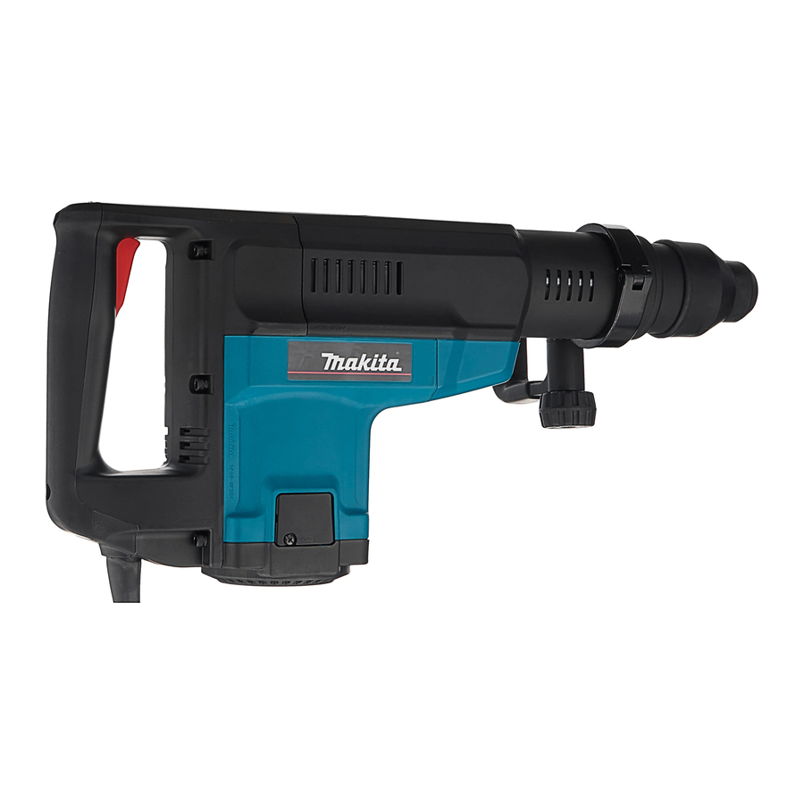
Makita HR5001C Technical Information
50mm rotary hammer
Hide thumbs
Also See for HR5001C:
- Instruction manual (52 pages) ,
- Parts breakdown (4 pages) ,
- Instruction manual (45 pages)
Table of Contents
Advertisement
Quick Links
Download this manual
See also:
Instruction Manual
T
ECHNICAL INFORMATION
Models No.
Models No.
Description
Description
C
ONCEPTION AND MAIN APPLICATIONS
Model HR5001C is 50 mm rotary hammer for the SSDS-max bit
designed as the sister version the existing Model HR4000C.
Its brief benefits are;
*Can achive the highest efficiency in this class.
*Electrical speed control feature
Variable speed
Soft start
Steady speed
S
pecifications
Voltage(V)
100
110
120
220
230
240
No load speed
Bit type
Max.capacities
Net weight
Cord length
S
tandard equipment
Grease Vessel ------------------1 pc.
Plastic Carrying Case --------1 pc.
Bar-type handle ---------------1 pc.
D-type handle -----------------1 pc.
O
ptional accessories
T.C.T.Bit : 19(3/4"), 20(15/16"), 21.5(7/8"), 22(7/8"), 25(1"), 28(1-1/8"), 32(1-3/8"), 35(1-3/8"), 38(1-1/2")
Bull point 280, 400
Clay Spade
Core bit adapteer
Core bit : 20(15/16"), 30(1-3/16"), 35(1-3/8"), 40(1-9/16"), 45(1-3/4"), 54(2-1/8"), 65(2-9/16"),
79(1-1/8"), 105(4-1/8") , 118(4-5/8")
Grease Vessel(Bit grease,Hammer grease)
F
eatures and benefits
1. Double insulated
2. See the sheets attached for more information
HR5001C
50mm Rotary Hammer
Current(A)
Cycle(Hz)
15
50/60
15
50/60
15
50/60
7.7
50/60
7.4
50/60
7.1
50/60
Rotations per minute
Blows per minute
(Work : Concrete)
Cold chisel 25~280,25~400
D-type side handle
Depth Gauge
Continuous Rating(W)
Input
Output
1450
460
1500
600
1500
600
1500
600
1500
600
1500
600
120 ~ 240rpm
1100 ~ 2150bpm
SDS-max. shank
Diameter of shank : 18 mm(11/16'')
T.C.T.Bit:50mm(2")
Core bit : 160 mm(6-5/16")
10Kg(22bs)
5m(16.4ft)
Scaling chisel 50
Safety Goggle
118 (4-5/8")
610
(24")
Max.Output(W)
1400
1900
1900
1900
1900
1900
Tile chisel 50
New Tool
Advertisement
Table of Contents

Related Manuals for Makita HR5001C


Summary of Contents for Makita HR5001C
- Page 1 Description 50mm Rotary Hammer ONCEPTION AND MAIN APPLICATIONS Model HR5001C is 50 mm rotary hammer for the SSDS-max bit designed as the sister version the existing Model HR4000C. Its brief benefits are; *Can achive the highest efficiency in this class.
- Page 2 270mm 200mm Holding power required when torque limiter operating Approx. 20 kgf Approx. 29 kgf Speed adjustable dial Makita #HR5001C Bosch #GBH10DC Light hammering or drilling is easily performed Longer life motor Large model plastic case by setting lower speed.
- Page 3 Repair (1) Removing Change lever ------------------------------ ------(Page 6 of 14) (2) Install Change lever ------------------------------- ----------(Page 6 of 14) (3) Replace the Armature ------------------------------- --------(Page 7 of 14) (4) Disassembling the chuck --------------------------- -------(Page 8 of 14) (5) Assembling the chuck ------------------------------- -------(Page 8 of 14) (6) Removing Tool holderers --------------------------- ------(Page 8 of 14) (7) Disassembling tool holders ------------------------- -------(Page 9 of 14) (8) Assembling the tool holder A and B ----------------- -----(Page 9 of 14)
- Page 4 •Removing Change lever(same as HR4000C) a. Set the change lever at neutral position, and slightly Resin hammer Lock button hit the back side of the lock button using the resin hammer to remove it.(See the figure 1.) Change lever •Installing Change lever (same as HR4000C) a.
- Page 5 •Replacing Armature a. Slide down Chuck cover and remove Tool holder cap.(See the figure 4.) Tool holder cap b. Remove pan head screws, and then remove Crank housing cover and Gear housing cover.(See the figure 4.) c. Remove hex.socket head bolts and then remove handle.(See the figure 5.) Chuck cover d.
- Page 6 ¥Disassembling the chuck(See the figure 10.) a. Remove Tool holder cap, Chuck cover and Crank housing cover. b. Remove ring spring 25. c. Remove Retaining ring WR-45. To remove Ring spring 25 and the Retaining ring WR-45, using retaining ring pliers is recommended. d.
- Page 7 Disassembling the tool holder a. Remove Retaining WR-50. To remove Retaining WR-50, use retaining ring plier. b. To disconnect the ball bearing 6910,use gear puller withsupport plate (see the figure 15.) Support plate Gear puller Tool holder A Retaining WR-50 Ball bearing 6910 Figure 15 Assembling Tool holder A and B.(See the figure 16.)
- Page 8 Assembling Piston, Rod and Crank shaft(see the figure 18.) a. Set the 3 pieces of O ring 36 on Cylinder 40, and insert them into the crank housing. b. Insert the piston until the rod hole is placed inside the crank room. c.
- Page 9 Assembling the tool holder a. Set the parts described below into the crank housing.(See the figure 20.) b. To set the spiral bevel gear 41, use the tool holder wit h out mounting the lock sleeve for smooth setting.(See the figure 21.) •Striker(mounted with O ring 34) •Washer 45 •Ring 45...
- Page 10 Assembling the torque limiter(Same as HR4000C) a. Assemble the ball bearing 6201, Flat washer 12(Outer dia. 24 mm) and torque limiter complete into the spiral bevel gear 12. (See the figure 24.) Flat washer 12 Note ) Use care not to miss the pin 4 for preventing Groove of change key (Outer dia.
- Page 11 Lubication To prevent abrasion and overheating, please apply the MAKITA grease R No.00 at the positions shown below. a. O ring of striker b. Inside of ring 45 c. Inner of slide sleeve d. Outside and gear of Spiral bevel gear 41...
- Page 12 (Page 14 of 14) iring diagram Brush holder Black White Connector Switch Violet Field Orange Power supply cord Controller Black Orange White Brush holder Connector...
Need help?
Do you have a question about the HR5001C and is the answer not in the manual?
Questions and answers