Table of Contents
Advertisement
®
PYROTECH
2012
INSTALLATION & OPERATING MANUAL
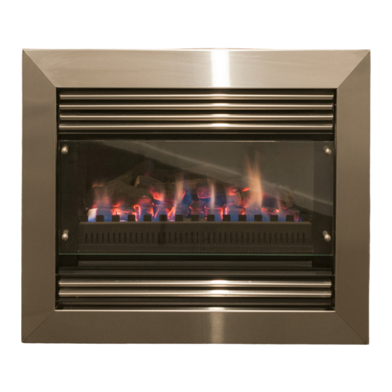
The Pyrotech Space Heater range are approved to be installed into a
masonry fireplace, as a zero clearance firebox enclosed by a timber
frame and plastered or as a free standing unit. The Pyrotech Range is
approved to operate on Natural Gas and Propane (LPG) gases only.
Approval Number: GMK10092
VERSION 12
Advertisement
Table of Contents
Troubleshooting

Summary of Contents for RealFlame PYROTECH
- Page 1 The Pyrotech Space Heater range are approved to be installed into a masonry fireplace, as a zero clearance firebox enclosed by a timber frame and plastered or as a free standing unit. The Pyrotech Range is approved to operate on Natural Gas and Propane (LPG) gases only.
-
Page 2: Warranty Information
You must register to receive the benefit of this warranty by completing the warranty registration on our website (www.realflame.com.au) or completing and mailing the attached registration card within 30 days of purchase of your Real Flame Gas Burner (or, if the Real Flame Gas Burner is fitted to a new home, within 30 days of the date of settlement of purchase of such new home). -
Page 3: Ventilation Requirements
WARNING The Pyrotech range of fires have a primary safety glass fitted in front of the glass door. This safety glass is fitted to this appliance to reduce the risk of injury from burns and at no time should this glass be permanently removed. -
Page 4: Table Of Contents
Parts Location/Parts Kit (Standard models only)...........25 Gas Control Assembly/Valve Description ..............26 Parts List (Deluxe models only) ................27 Gas Control Assembly ...................28 Troubleshooting for Pyrotech Standard ..............29 Troubleshooting for Pyrotech Deluxe ..............30 Flue Termination Regulations ................31 Optional Marble Surround Installation Procedure..........32 Optional Mantelpiece Installation Procedure/Dimensions ........33... -
Page 5: Data Plate
DATA PLATE MODEL: WEIGHT: PYROTECH STANDARD 2012 56 kg TYPE INJ/SIZE MJ/H P .T.P . 2 x 1.65mm 1.00 kpa HIGH NG PRIMARY 2 x 1.65mm 21.5 0.63 kpa LOW NG SECONDARY 2 x 1.05mm 2.55 kpa HIGH LPG PRIMARY 2 x 1.05mm... -
Page 6: Inbuilt Model Dimensions/Installation Procedure
45mm 40mm 240mm 170mm 30mm Electrical Cord Pyrotech Inbuilt Installation Procedure TICK BOXES Check chimney for correct venting of fumes Position unit centrally. Connect to gas supply using 15mm copper union. Connect to power supply. Remove glass and assemble log or pebble set as shown (Figures 1 - 12). - Page 7 PYROTECH INBUILT MODEL Pyrotech Inbuilt Installation Procedure (continued) Figure (3) Remove nylon grommets and put Figure (4) Remove three spacer bolts, and aside carefully. loosen bolt in bottom right corner. NOTE: Keep coals or pebbles clear of burner rail. Figure (5) Support front glass as shown, and remove fourth spacer bolt.
- Page 8 Pyrotech Inbuilt Installation Procedure (continued) The Pyrotech Space Heater (Natural Gas Only) is approved for use with Pebbles. To install the Pebbles follow the installation instructions as per Figures 1 to 5 above, and then proceed as follows (Figures 10 to 12).
-
Page 9: Zero Clearance Model Timber Frame Installation Procedure
PYROTECH ZERO CLEARANCE MODEL Pyrotech Zero Clearance Timber Frame Installation (Recommended only) (Recommended only) IMPORTANT Install unit and fluing before plasterboard. Plaster to run beyond stud and behind trim HEATER From hearth TRIM Approx 20mm for hearth if required. NOTE: Note: If fire is to be installed off the floor with 4 sided trim, use same A, B, C and D dimensions as shown with frame work included below fire to required height. -
Page 10: Zero Clearance Model
PYROTECH ZERO CLEARANCE MODEL Position the Pyrotech firebox in the selected installation position in the room. You will require the Zero Clearance Kit to suit, which is to be fitted to the main fire box as shown on page 11. -
Page 11: Zero Clearance Model Assembly
PYROTECH ZERO CLEARANCE MODEL Fit Zero Clearance Kit to unit as shown below: ITEM 1 ITEM 5 ITEM 2 ITEM 4 ITEM 6 ITEM 3 Secure side strips (Item 1) to side brackets on fire Place LH side panel (Item 4) in behind lip of base box using screws (2 off per side strip). -
Page 12: Zero Clearance Model Dimensions/Installation Procedure
PYROTECH ZERO CLEARANCE MODEL Pyrotech Zero Clearance Installation Procedure TICK BOXES Connect to gas supply. Connect to power supply Install flue to 500mm minimum above roof line. (Min total flue run 3.6 m) Plaster to unit with trim removed. Install trim. -
Page 13: Freestanding Model Dimensions
PYROTECH FREESTANDING MODEL Cowl 460mm 780mm 840mm 40mm Power 50mm 40mm Ceiling Ring 50mm 4 x 900m Flue Lengths Ceiling Ring 30mm 460mm 740mm STANDARD FLUE KIT... -
Page 14: Freestanding Model Installation Procedure/Clearances
PYROTECH FREESTANDING MODEL Pyrotech Freestanding Installation Procedure TICK BOXES Position unit maintaining correct clearances from combustibles. Connect to adequate gas supply. Connect to adequate power supply. Install flue kit maintaining minimum 25mm clearances from outer flue to combustibles. Assemble as per pages 6 - 8. -
Page 15: Flue Requirements
FLUE REQUIREMENTS Natural Draught The standard natural draught flue kit consists of 4 x 900mm lengths of twin skin flue (refer to page 6 for correct sizing) and an AGA approved cowl. 200mm 2 lengths above 500mm last bend 200mm Max. -
Page 16: Dimensions
DIMENSIONS Pyrotech Inbuilt Pyrotech ZC Trim FRONT - 3 SIDED FRONT - 4 SIDED... - Page 17 DIMENSIONS Pyrotech Freestanding...
-
Page 18: Lighting Pilot And Main Burner (Standard Models Only)
APPROXIMATELY 60 SECONDS FOR THE VALVE TO RELEASE AND ALLOW YOU TO MOVE THE KNOB. DO NOT FORCE THE KNOB. To adjust the heat output of your Pyrotech, simply turn the Hi/Lo control knob to the right of the control knob. -
Page 19: Tests To Be Carried Out By Installer
TO TURN OFF GAS TO APPLIANCE Turn switch to “OFF” position. Push in gas control knob slightly and turn to the off position. Control Knob Hi/Lo Gas Hi/Lo Fan On/Off Louvre Door TESTS TO BE CARRIED OUT BY INSTALLER • Check unit for gas leaks. -
Page 20: Servicing And Maintenance
SERVICING AND MAINTENANCE It is To follow when servicing, recommended removing fan or changing that you have valve or control modules. your Real Flame IMPORTANT: POWER MUST BE fire serviced ISOLATED PRIOR TO CARRYING every two years. OUT THE SERVICE/MAINTENANCE. This work should SERVICE/MAINTENANCE ONLY TO only be carried... - Page 21 Figure (8) Remove coals/logs or pebbles and Figure (9) securely store to prevent damage. Figure (10) Remove front iron from burner. Figure (11) Remove burner holding screws on each side of burner. Figure (12) Remove log positioning panel Figure (13) Remove log positioning panel. screw at rear of firebox.
- Page 22 Figure (16) Remove burner from firebox Figure (17) Remove the nine screws securing the base to the firebox from the back of the base... Figure (18) ...and the sides of the base. Figure (19) Lift the base plate to expose the flexi burner tube.
- Page 23 Removal of Fan Figure (1) Remove the wing nuts from each Figure (2) Tilt fan back and slide out. side of fan and remove holding plates. Figure (3) Lift fan out... Figure (4) ...and disconnect power plug to remove fan. Removal of Control Module Deluxe model only...
- Page 24 Removal of Control Valve Deluxe model only Figure (1) Remove valve modulating lead Figure (2) Disconnect gas from control valve. from control valve. Figure (3) Remove wing nuts from each of the control valve holding brackets and remove valve. Removal of Millennium Control Module Deluxe model only...
-
Page 25: Parts Location/Parts Kit (Standard Models Only)
PARTS LOCATION (STANDARD MODELS ONLY) 865mm 635mm Pilot Power Generator Valve assembly on/off hi/lo fan 95mm switch switch Piezo Ignitor PARTS KIT Pilot Thermocouple Piezo Lead Power Generator Piezo Ignitor Valve... -
Page 26: Gas Control Assembly/Valve Description
GAS CONTROL ASSEMBLY PART PART No. AGA Approval SIT 820 NOVA Mv 0820332-NAT GAS 4032 SIT 820 NOVA Mv 0820331-LPG 4032 SIT THERMOCOUPLE 200261 4032 SIT PILOT ASSEMBLY 190610 4032 SIT THERMAL GENERATOR 240002 4032 PIEZO WITH LEAD 28510 4032 PIEZO IGNITOR PUSH BUTTON 73953 4032... -
Page 27: Parts List (Deluxe Models Only)
PARTS LIST (DELUXE MODELS ONLY) Gas Control Valve Module Box Remote Control Module Remote Control 1. Pilot 2. Pilot Tube 3. Burner Tube... -
Page 28: Gas Control Assembly
GAS CONTROL ASSEMBLY Inlet Test Adjustment Outet Test Pressure Point for High Pressure Point Gas Inlet Gas Outlet Adjustment for Low... -
Page 29: Troubleshooting For Pyrotech Standard
TROUBLESHOOTING FOR PYROTECH STANDARD IMPORTANT Valve system troubleshooting should only be carried out by a qualified service technician. If supply cord is damaged or the unit needs repairing, it shall be repaired by the manufacturer or its service agent or similarly qualified person in order to avoid a hazard. -
Page 30: Troubleshooting For Pyrotech Deluxe
Refer to page 5. IF YOUR PYROTECH STANDARD FIREPLACE STILL DOES NOT OPERATE CORRECTLY CONSULT YOUR DEALER. ALL SERVICE AND REPAIRS SHOULD BE PERFORMED BY AN AUTHORISED AGENCY. ALL SPARE PARTS AND OPTIONAL TRIM FINISHES ARE AVAILABLE FROM REAL FLAME PTY LTD. -
Page 31: Flue Termination Regulations
PYROTECH FLUE TERMINATION (COWLS) REGULATIONS Natural Draft Refer to Note 1 Refer to Note 1 A OR B 500mm 500mm AREA CLEARANCE REQUIRED Horizontally from a neighboring structure............1000mm If less than a meter horizontally from a neighboring structure then terminates above that structure by............500mm From any opening into a building..............1500mm... -
Page 32: Optional Marble Surround Installation Procedure
Marble Margin Set Installation Procedure Install Pyrotech without trim. Install marble up to flange on Pyrotech. Use liquid nails to fix to wall. Marble should look like the diagram below once it has been installed and before mantelpiece has been attached. -
Page 33: Optional Mantelpiece Installation Procedure/Dimensions
OPTIONAL MANTELPIECE INSTALLATION (Inbuilt & ZC models only) MANTELPIECE DIMENSIONS MODEL 1810 1220 1090 Universal* 1440 1210 Victorian Arch 1440 1215 Federation Square * Universal Windsor, Bouvier, Kensington, Freidrich Firebox Plaster Marble Trim Mantel NOTE: If using a cast fascia inside a mantel a special trim needs to be ordered. See your Real Flame stockist for details. -
Page 34: Electrical Diagram (Standard Models Only)
ELECTRICAL DIAGRAM (STANDARD MODELS ONLY) Temperature Fan Switch Thermostat Orange Orange Brown Blue Blue White White (Low) Brown Black (Med) Green/Yellow Green/Yellow Burner On/Off Blue Switch Room Air Fan Brown (Not used) Millivolt Valve... -
Page 35: Electrical Diagram (Deluxe Models Only)
ELECTRICAL DIAGRAM (DELUXE MODELS ONLY) SIT 579DBC Spark Ignition and Gas Valve Control Flame Sensing Green/Yellow Green/Yellow Brown Brown Temperature Blue Blue High Limit Green/Yellow Green/Yellow Black (Med) Purple Blue White (Low) White Brown Room Blue Blue Gas Valve Air Fan Modulation Coil A LOW MED TH1 TH2 MOD1 MOD2... -
Page 36: Real Flame Contact Information
CHEMINEE PTY LTD EMAIL sales@cheminee.com.au WEBSITE www.Cheminee.com.au PHONE 02 9564 2694 FAX 02 9569 8802 SHOWROOM 118 Stanmore Road, Stanmore (Corner Wemyss St) NSW...
Need help?
Do you have a question about the PYROTECH and is the answer not in the manual?
Questions and answers