Table of Contents

Advertisement

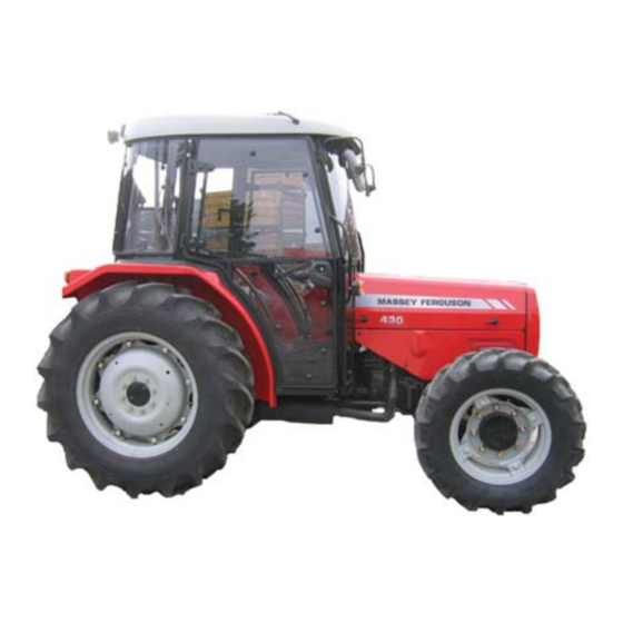
Tractor models applicable:
For footstep tractor models:
410,420,430
Manufactured from January 2007.
European market only.
Published by:
UZEL Mak.San.A.S.
Istanbul,
Turkiye
410/420/430 - 001 8903 U1
UZEL
410/420/430 Tractor
Operator Instruction Book
Contents
General Information
Tractor identification.
Introduction.
Warranty, pre-delivery and installation on the farm.
Safety notes.
Safety signs.
Controls and Instruments
Controls.
Instruments.
Operation
Starting.
Running-in.
Operating the tractor.
Maintenance and Adjustment
Maintenance chart.
Recommended lubricants.
Servicing the tractor.
Greasing, checking levels and changing oil.
Adjustments - axles, brakes and wheels.
Replacements - fuses, bulbs and battery.
Fuel storage.
Specification
Alphabetical Index
Page
3
23
35
57
101
115
November 2006,
001 8903 U1
Issue 2
UZEL 2006
1

Advertisement

Table of Contents
loading

Summary of Contents for MASSEY FERGUSON 410

  • Page 1 Greasing, checking levels and changing oil. Adjustments - axles, brakes and wheels. Replacements - fuses, bulbs and battery. Fuel storage. Specification Alphabetical Index Published by: November 2006, UZEL Mak.San.A.S. 001 8903 U1 Istanbul, Issue 2 Turkiye UZEL 2006 410/420/430 - 001 8903 U1 UZEL...
  • Page 2: Tractor Identification

    Tractor Identification Serial Numbers NOTE: Observe the serial numbers of your tractor. Always quote the serial numbers in any communication to your Massey Ferguson Dealer. Model ------------------------------------------------------------- ------------------------------------------------------------- Fig. 1 Tractor Serial No. (Fig. 1) ------------------------------------------------------------- Engine Serial No. (Fig. 2)
  • Page 3: Table Of Contents

    Follow a Safety programme -------------------------------------------------------------------------------------------------------- 8 Protective Structures ----------------------------------------------------------------------------------------------------------------- 9 Prepare for Safe operation ------------------------------------------------------------------------------------------------------- 10 Servicing the Tractor ---------------------------------------------------------------------------------------------------------------- 12 Starting ---------------------------------------------------------------------------------------------------------------------------------- 13 Work Safely ---------------------------------------------------------------------------------------------------------------------------- 14 After Operation ------------------------------------------------------------------------------------------------------------------------ 19 Safety Signs and Locations ------------------------------------------------------------------------------------------------------ 20 410/420/430 - 001 8903 U1 UZEL...
  • Page 4: Introduction

    Since this book Full details of equipment available in your area can is published for worldwide circulation, it is impossible be obtained from your Massey Ferguson Dealer. Use to detail the exact terms and conditions of warranty only Massey Ferguson approved attachments that apply to a retail customer in any particular country.
  • Page 5: Safety

    Parts warning WARNING: In some of the illustration used in this Operator Instruction Book, The fitment of non Massey Ferguson parts may result panels or guards may have been removed for clarity. Never operate the in a part of substandard quality being used. Massey...
  • Page 6 Introduction Page intentionally blank 410/420/430 - 001 8903 U1 UZEL...
  • Page 7: Safety Alert Symbol And Terms

    Massey Ferguson has no direct programme. Keep in mind that this safety section is control over tractor application, operation, inspection, written only for this type of machine.
  • Page 8: Follow A Safety Programme

    This includes tractors. It is your responsibility to know what these regulations are, and obey them, in the operating area or situation. These will include, but are not limited to, the following instructions for safe tractor operation. 410/420/430 - 001 8903 U1 UZEL...
  • Page 9: Protective Structures

    Before you operate the tractor, replace all damaged parts. DO NOT WELD, DRILL, BEND OR STRAIGHTEN THE ROPS. To do so reduces the protection it offers. 410/420/430 - 001 8903 U1 UZEL...
  • Page 10: Prepare For Safe Operation

    Dealer) TO EXPLAIN IT TO YOU. IMPORTANT: This manual covers general safe practices for agricultural tractors. It must always be kept with the tractor. For further copies contact your Massey Ferguson Dealer Fig. 7 410/420/430 - 001 8903 U1 UZEL...
  • Page 11 DO NOT use your bare hand. Wear safety goggles for eye protection. If any fluid is injected into the skin, it MUST be surgically removed within a few hours by a doctor familiar with this type of injury (see Fig.9) 410/420/430 - 001 8903 U1 UZEL...
  • Page 12: Servicing The Tractor

    NOT a hydraulic jack. *Check all nuts and bolts periodically for tightness, especially wheel hub and rim nuts. Tighten to the prescribed torque values. *Check the brakes regularly. Adjust when necessary. 410/420/430 - 001 8903 U1 UZEL...
  • Page 13: Starting

    After starting, re-check all gauges and lights. Make sure everything is functioning correctly. If the tractor does not respond correctly when each control is operated, DO NOT use the machine until the fault is rectified. 410/420/430 - 001 8903 U1 UZEL...
  • Page 14: Work Safely

    If differ ential is locked, DO NOT operate at high speed or turn the tractor until the differential lock is disengaged. *DO NOT lift a load over anyone (Fig. 14). 410/420/430 - 001 8903 U1 UZEL...
  • Page 15 Shift into gear before you start downhill. *Engage powered front axle (if fitted), this will give four wheel braking. 410/420/430 - 001 8903 U1 UZEL...
  • Page 16 Keep the loader bucket as low as possible. *Always keep the tractor in gear when going downhill. DO NOT permit the tractor to coast with clutch disengaged or transmission in neutral. Fig. 17 410/420/430 - 001 8903 U1 UZEL...
  • Page 17 To adjust wheel settings refer to Maintenance and Adjustment section. *Reduce your speed when operating over rough or slippery ground and when foliage restricts your view of hazards. *DO NOT make sharp turns at high speed. 410/420/430 - 001 8903 U1 UZEL...
  • Page 18 Provide only enough slack in the chain to permit turning. See your Massey Ferguson Dealer for a chain with a strength rating equal to, or greater than the gross weight of the towed machine (Fig. 20).
  • Page 19: After Operation

    When stopping at any time, bring the tractor to a complete halt, apply the parking brake, disengage the PTO, place all gear shift levers in neutral, lower the implement to the ground, stop the engine and remove the key BEFORE leaving the seat. 410/420/430 - 001 8903 U1 UZEL...
  • Page 20 Radiator cap decal- Located on left and right hand side of the radiator. Located on the radiator. 3774440 M1 Hazardous surfaces decals- Located on left and right hand side of the radiator. Fig. 23 410/420/430 - 001 8903 U1 UZEL...
  • Page 21 Rear warning decal- Located on the starter motor Located on the rear right hand fender 0017611 U1 0017612 U1 Battery warning decal- Battery warning decal- Located on the battery. Located on the battery Fig. 24 410/420/430 - 001 8903 U1 UZEL...
  • Page 22 Safety Notes Page intentionally blank. 410/420/430 - 001 8903 U1 UZEL...
  • Page 23 Controls and Instruments Contents Page Instruments ---------------------------------------------------------------------------------------------------------------------------- 24 Indicator lights ------------------------------------------------------------------------------------------------------------------------ 26 Controls - Operating ---------------------------------------------------------------------------------------------------------------- 27 Controls - General ------------------------------------------------------------------------------------------------------------------ 30 Grammer Seat ------------------------------------------------------------------------------------------------------------------------ 31 Cab Controls ------------------------------------------------------------------------------------------------------------------------ 34 410/420/430 - 001 8903 U1 UZEL...
  • Page 24: Instruments

    2. Auxiliary / run. This position permits the electrical services to be switched on without the engine running. Switch returns to this position after engine starting. 3. Pre-heat. Moving the key to the pre-heat position 410/420/430 - 001 8903 U1 UZEL...
  • Page 25 11. Flashing Warning Lights Switch When the flashing warning light switch is used (Fig. Fig. 27A 27A) , all the turn indicators will flash in unison and the switch will flash a red triangle. 410/420/430 - 001 8903 U1 UZEL...
  • Page 26: Indicator Lights

    If the light still comes on contact your engine speed. The light will come on if the starter Massey Ferguson Dealer to correct the fault. switch key is moved to the 'OFF' position when the engine is running, and will come on briefly as the Oil filter/ Dry air filter light engine stops.
  • Page 27: Controls - Operating

    L - LOW KEY or O SYMBOL - Neutral Start position. KEY SYMBOL for non shuttle tractor - MF 410 Operation of the foot throttle overrides the hand O SYMBOL for shuttle tractor - MF 420/430 throttle setting when increasing engine speed. When...
  • Page 28 Power Take -off shaft. On tractors fitted with Independent Power Take-off (IPTO) the clutch pedal is single stage, engaging and disengaging the drive to the transmission only. Fig. 31 410/420/430 - 001 8903 U1 UZEL...
  • Page 29 This lever engages the four-wheel drive when pushed "DOWN". For details - (see page 41) 13. Control valve lever(s) These levers control auxiliary hydraulic equipment (Fig. 33). For details of operation - (see page 48). Fig. 32A Fig. 33 410/420/430 - 001 8903 U1 UZEL...
  • Page 30: Controls - General

    Rear work light The rear work light (Fig. 36) is operated by a sliding switch on the back of the light. Rear work light can only be used when the parking lights are on. Fig. 36 410/420/430 - 001 8903 U1 UZEL...
  • Page 31: Grammer Seat

    To adjust forward and backward movement of the seat, pull the lever (3) up to disengage the runner lock, then slide the seat either forward or backward as required. Release the lever so it locks into position. Fig. 38 410/420/430 - 001 8903 U1 UZEL...
  • Page 32 Slide the end along the webbing to take up any slack after final adjustment. When not in use, the seat belt should be stored on the clip provided to keep it from being damaged or becoming dirty. Fig. 40 410/420/430 - 001 8903 U1 UZEL...
  • Page 33 Slow Moving Vehicle (SMV) warning triangle (Fig.41). If the SMV sign is lost or in need of replacement, it can be obtained from your Massey Ferguson Dealer part number 3789 701 M1. Fig. 41 Tool box A tool box (Fig.
  • Page 34 A tool box is located in front of the left-hand step. Fig. 43-c Windscreen washer reservoir (Fig. 43-d) A reservoir is mounted on the right fender. WARNING: The liquid level should be always checked before driving. Fig. 43-d 410/420/430 - 001 8903 U1 UZEL...
  • Page 35 Lifting linkage ------------------------------------------------------------------------------------------------------------------------- 51 Attaching an implement ------------------------------------------------------------------------------------------------------------- 54 Detaching an implement ------------------------------------------------------------------------------------------------------------ 54 Attaching and detaching trailed equipment ------------------------------------------------------------------------------------ 54 Swinging drawbar -------------------------------------------------------------------------------------------------------------------- 56 Front-mounted weight frame ------------------------------------------------------------------------------------------------------ 56 Roll-over protective structure (ROPS) ------------------------------------------------------------------------------------------ 56 410/420/430 - 001 8903 U1 UZEL...
  • Page 36: Starting And Stopping The Engine

    4. Depress the clutch and brake pedals. Attempt to start the tractor with the gears (shuttle lever if fitted) in neutral and the PTO engaged. The starter should NOT operate. If either switch is not working correctly it must be replaced immediately. 410/420/430 - 001 8903 U1 UZEL...
  • Page 37: Normal Starting - Cold Weather (Glow Plugs)

    The engine should run at low idle smoothly until speed is gradually increased to high idle. Allow the white smoke to disperse before proceeding with normal operation. 410/420/430 - 001 8903 U1 UZEL...
  • Page 38: Stopping The Engine

    In the event of a failure or the need to shut the engine Down, turn the ignition switch OFF first. Then if the engine does not stop disconnect the cable plug from the solenoid on the injection pump (Fig. 45). Fig. 45 410/420/430 - 001 8903 U1 UZEL...
  • Page 39 8 kph (5 mph) road speed, in this case it is the bar for 5th gear. NOTE: Refer to the speed chart on your tractor for the correct gear and speed range. 410/420/430 - 001 8903 U1 UZEL...
  • Page 40: Operating The Tractor

    See your 5. Never coast down slopes with the tractor in gear Massey Ferguson Dealer for special water-proofing and the clutch disengaged, or with the transmission instructions, otherwise the Warranty may be in neutral.
  • Page 41 H - High - Transport range. Key symbol - Neutral - Start. L - Low - Work range. 8 x 2 Syncromesh Gearbox - 410 The main gear lever (1,Fig. 48) provides the operating gears within the range selected. The range lever on the right (2) selects the range, forwards for LOW (L) and backwards for HIGH (H) range.
  • Page 42: Brakes

    Fig. 52 IMPORTANT: DO NOT attempt to engage the differential lock with one wheel stopped and the other wheel spinning fast. DO NOT attempt to turn with the differential lock engaged. 410/420/430 - 001 8903 U1 UZEL...
  • Page 43: Power Take-Off (Pto)

    There are two types of Power Take-Off (PTO) available, Direct Drive from the engine using a dual clutch and mechanical engagement (MF 410 only). The second type ( MF410/420/430 ) is an Independent Power Take -Off (IPTO) using a single split torque clutch and hydraulic engagement.
  • Page 44: Attaching To The Pto Shaft

    'A' between the end of the PTO shaft and the pin hole in the end of the drawbar is 356 mm, (14 in) if using the six spline 540 rev/min shaft. Fig. 56 410/420/430 - 001 8903 U1 UZEL...
  • Page 45: Hydraulic Lift System

    Operation Creeper gearbox (optional for MF 410/420/430) The creeper gearbox is located between the transmission and the rear axle housing. It gives the option of reducing the speed of the tractor in the ratio of 4:1, beside allowing the use of normal speeds.
  • Page 46: Draft Control - Outer Lever - Yellow Quadrant

    No further adjustment is necessary. Leaving work: Move the Position Control Lever (2) up to the TRANSPORT position, if required. Re-enter work by moving the Position Control Lever forward to the Adjustable Stop. Fig. 61 410/420/430 - 001 8903 U1 UZEL...
  • Page 47: Transport Position

    5. Raise and lower the implement using fender mounted auxiliary valve. Fig. 63 To resume three-point operation: 1. Move the position control lever out of constant pumping to DOWN. 2. Return selector valve to three-point hitch position. 410/420/430 - 001 8903 U1 UZEL...
  • Page 48: Auxiliary Hydraulic Control

    (1, Fig. 65) and the return hose to the coupler marked (2). To extend the ram, pull the lever back. To retract the ram, push the lever forwards. Fig. 66 410/420/430 - 001 8903 U1 UZEL...
  • Page 49: Operation - Hydraulic Motors

    1. Always connect the motor feed to the coupler (1 or 2, Fig. 65). 2. NEVER connect the motor return to the quick- release couplers. Contact your Massey Ferguson Dealer when fitting a hydraulic motor to ensure that the hydraulic circuit is completely satisfactory and the return line is connected directly to the transmission case.
  • Page 50: Lifting Linkage

    7. Levelling lever. NOTE: The lift rod bolts must always be adjusted so 8. Top link stowage hook. that they can rotate. The bolts must also be through the corresponding holes in both lower link arms. 410/420/430 - 001 8903 U1 UZEL...
  • Page 51 1. For fine adjustment (Fig. 68). Rotate the turnbuckle(1) as required. 2. For coarse adjustment, remove the lock pin (2) and lengthen or shorten the stabilizer as required. Fig. 68 Replace the lock pin. 410/420/430 - 001 8903 U1 UZEL...
  • Page 52: Attaching An Implement

    9. Adjust the length of the stabilizer (Fig. 68). 10. Connect the implement to the PTO shaft, if required, and attach guards (see page 43). 11. Raise and lower the implement, checking clearances and general operation. 410/420/430 - 001 8903 U1 UZEL...
  • Page 53: Detaching An Implement

    After attaching the safety chain, make a trial run by driving the tractor to the right and to the left for a short distance to check the safety chain adjustment. If necessary, readjust to eliminate tight or loose chain. 410/420/430 - 001 8903 U1 UZEL...
  • Page 54: Attaching And Detaching Trailed Equipment

    (1710 lbft ) 775 kgf Outer position 410 mm (16 in) (1710 lbft ) Table 2 : distance from the clevis hitch point 'X' to the PTO shaft and the maximum vertical static loadings. 410/420/430 - 001 8903 U1 UZEL...
  • Page 55 420 Nm (310 lbf ft). The lock-nuts securing the drawbar frame must be kept tightened to a torque of 245 Nm (180 lbf ft). 410/420/430 - 001 8903 U1 UZEL...
  • Page 56: Front-Mounted Weight Frame

    DO - ensure that all components are in correct working order in order to provide the intended protection. DO - use only original Massey Ferguson supplied parts to maintain structural integrity. WARNING: The following additional safety precautions must be strictly observed: Fig.
  • Page 57 Maintenance and Adjustment Contents Page Maintenance chart ------------------------------------------------------------------------------------------------------------------ 58 Tractor lubrication chart ------------------------------------------------------------------------------------------------------------ 59 Massey Ferguson recommended lubricants ----------------------------------------------------------------------------------- 60 Grease lubrication points ----------------------------------------------------------------------------------------------------------- 61 Maintenance and adjustment ----------------------------------------------------------------------------------------------------- 64 Safety in servicing ------------------------------------------------------------------------------------------------------------------- 64 Service access ------------------------------------------------------------------------------------------------------------------------ 65 Engine oil ------------------------------------------------------------------------------------------------------------------------------- 67...
  • Page 58: Maintenance Chart

    NOTE: ** Flexible maintenance times vary according to individual conditions of operation. You must establish times for servicing flexible items. An average interval time for checking these items is at each fuel fill. 410/420/430 - 001 8903 U1 UZEL...
  • Page 59: Tractor Lubrication Chart

    Maintenance and Adjustment Tractor lubrication chart Fig. 78 410/420/430 - 001 8903 U1 UZEL...
  • Page 60 0.2 liters (0.35 US pints ) 20.11 SD type Four-wheel Drive Front Axle (MF 430 only) Capacity: Axle 5.5 liters (1.5 US gal ) Planetery hub (each side) 0.2 liters (0.42 US pints ) 410/420/430 - 001 8903 U1 UZEL...
  • Page 61 *Ingestion: DO NOT induce vomiting. Administer 250 ml (1/2 pint) milk or 50 ml olive oil. Seek medical advice. *Skin Contact: Remove by wiping, wash with soap and water. *Inhalation: Saturated vapor non-toxic at room temperature. - Remove from exposure. *Eye contact: Wash with large amounts of warm water. 410/420/430 - 001 8903 U1 UZEL...
  • Page 62 Front axle swivel pins - Four-wheel drive front axle. Grease every 100 hours - 1 point. Grease every 100 hours - 4 points. Universal joints - Four-wheel drive front axle. Grease every 100 hours - 2 points. 410/420/430 - 001 8903 U1 UZEL...
  • Page 63 Lift linkage. Brake pedal bearing/ Grease every 100 hours - 3 points. Grease every 100 hours - 1 point. Front axle pivot pin - two wheel drive Grease every 100 hours - 1 point. 410/420/430 - 001 8903 U1 UZEL...
  • Page 64: Safety In Servicing

    Safety in servicing the tractor has regular preventive maintenance. It is recommended that the major services (500 and 1000 hour) are conducted by your local Massey Ferguson Dealer under the Massey Ferguson Recommended WARNING: When changing oil it is Service Program. It must be remembered that the...
  • Page 65: Service Access

    To remove the radiator cap (Fig. 82), open the cover, press the radiator cap down and turn slowly counter clockwise to allow pressure to escape before removing it. This is particularly important if the engine is hot. Fig. 82 410/420/430 - 001 8903 U1 UZEL...
  • Page 66 1. Remove the top-side panels (1). 2. Remove the rear hood securing bolts located behind the side panels (2). 3. Remove the front hood securing bolts located behind the side panels (3). 4. Lift off the hood. Fig. 84 410/420/430 - 001 8903 U1 UZEL...
  • Page 67: Engine Oil

    NOTE: Run the engine to circulate the oil and check for leakage. Time must then be allowed for the oil to settle in the sump before rechecking the level. Top up if necessary. Fig. 87 410/420/430 - 001 8903 U1 UZEL...
  • Page 68: Fuel System

    The valve tip clearances should be checked by your immediately after air has been removed from the Massey Ferguson Dealer every 1500 hours. fuel system. NOTE: Running the engine for this period of time will help ensure that the pump is completely free of air.
  • Page 69: Air Cleaner

    The inner filter element (3,Fig. 93) is added to protect the engine should harmful particles pass through the main filter. This inner element should be changed every 1000 hours. DO NOT attempt to clean the inner element. Fig. 94 Fig. 95 410/420/430 - 001 8903 U1 UZEL...
  • Page 70: Cooling System

    Use clean water and a 50% antifreeze solution. 5. Run the engine for approximately five minutes to remove all air from the system. NOTE: It is advisable to use Massey Ferguson antifreeze, it contains inhibitors to protect your engine 410/420/430 - 001 8903 U1 UZEL...
  • Page 71: Clutch

    Check the coolant level and add coolant if needed. Check the hoses, radiator, and pump for leaks NOTE: It is advisable to use Massey Ferguson radiator fins antifreeze, it contains inhibitors to protect your engine. Clutch Main clutch adjustment Check the clutch adjustment every 100 hours.
  • Page 72: Brakes

    Maintenance and Adjustment Brakes Disc Brakes - MF 410/420/430 Check the brakes every 250 hours, or more frequently if heavy work is involved. Procedure to adjust the brakes: 1. With the rear wheels attached, jack up the rear of the tractor and place it on axle stands with the wheels clear of the ground.
  • Page 73 4. Unscrew the fork (3) so that the foot pedal casting just contacts the mounting bracket at the position indicated by arrow. 5. Tighten the lock-nut and return the seal to its original position. Fig.103 410/420/430 - 001 8903 U1 UZEL...
  • Page 74: Transmission And Hydraulics

    (Fig. 106) to the required level, with an approved oil. 7. After allowing time for the oil to settle, check the level of the oil, then, if necessary, add further oil and refit the filler plug. Fig.105 Fig.106 410/420/430 - 001 8903 U1 UZEL...
  • Page 75 7. Refit the strainer. Fig.108 8. Check that the gasket (3) is in good condition otherwise fit a new one. 9. Refit the cover plate with the four nuts, tighten securely. 10. Refit the two drain plugs. 410/420/430 - 001 8903 U1 UZEL...
  • Page 76: Front Axle

    Distance A must be 0-4 mm (0-0.156 in) greater than distance 3. Drive the tractor forward for half of a front wheel revolution. Check distance again. Fig.111 410/420/430 - 001 8903 U1 UZEL...
  • Page 77 3. Tighten the track rod lock-nut to a torque of 112 Nm (83 lbf-ft). Ensure that both track rods are the same length. Fig.113 410/420/430 - 001 8903 U1 UZEL...
  • Page 78 8. Check the front wheel alignment, see page (76- WITH WITH 6.00X16 8LBX15- 15 WHEEL WHEEL 1227 1384 (48 in) (54 in) 1328 1485 (52 in) (58 in) 1430 1586 (56 in) (62 in) 1532 1687 (60 in) (66 in) Fig.115 410/420/430 - 001 8903 U1 UZEL...
  • Page 79 Tighten the lock-nuts (2) after adjustment. CAUTION: Recheck the nut and bolt tighteness after 10 hours(2 hours if on loader work) re-tighten twice more at 10-hour intervals. This protects against the loosening that occurs from assemblies settling down. Fig.117 410/420/430 - 001 8903 U1 UZEL...
  • Page 80 (1) screwing in and out the two joint tie rods (3) equally till the toe-in is within the requested tolerance. After adjusting, screw in the lock nuts (2) of the guide rods (1) to the requested tightening torque (Fig. 120). Fig.120 410/420/430 - 001 8903 U1 UZEL...
  • Page 81 Adjust the mechanical steering stop, screwing in or out the stop bolt (Fig 120), locking it with the locknut (5) to 150 Nm torque. Fig.122 Steer completely towards the other side and repeat the same operations. (Fig. 123). Fig.123 410/420/430 - 001 8903 U1 UZEL...
  • Page 82 Maintenance and Adjustment Oil change and checks Fig.124 DESCRIPTION POSITION Oil filling and level plug Oil drain plug Oil breather Filling, drain and level plug of epicyclic reduction gear oil Greasing points 410/420/430 - 001 8903 U1 UZEL...
  • Page 83 55° - 2 Toe-in A° - 2 Differential oil capacity 5.5 litres Epicyclic reduction gear oil capacity each side 0.6 litres API GL4 Oil specification: MIL L2105 Pinion-driveshaft interface Ø= 100 mm SAE 1310 410/420/430 - 001 8903 U1 UZEL...
  • Page 84: Rear Track Adjustment - Pressed Steel Wheels

    Track settings below 1328 mm (52 in) may not be obtainable due to insufficient clearance between wheel and inside of fender. Minimum track setting cannot be obtained on tractors fitted with wide tires. 410/420/430 - 001 8903 U1 UZEL...
  • Page 85: Wheel Weights

    Maintenance and Adjustment Wheel weights Wheel weights are available for the rear wheels, consult with your local Massey Ferguson Dealer for the correct weights for your tractor. Only sufficient weight should be added to provide traction and stability. Adding more weight than necessary results in excessive loads being imposed on the tractor and a higher fuel consumption.
  • Page 86: Tires

    This extends the life of the tire. 4. If bolt-on weights are fitted, raise the pressures to suit the weight fitted, consult your Massey Ferguson Dealer. 5. Water ballasting details are quoted (see page 90) for a few of the many tire options available for these tractors.
  • Page 87 3. Rim diameter in inches. 40km/hour. 4. Load diameter in inches. 5. Load Index. (Table 8 on page 88) 6. Speed Symbol, A8 = 40 Km/h.(Table9 on page 88) 7. Maximum inflation pressure. 8. Old marking (ply rating). 410/420/430 - 001 8903 U1 UZEL...
  • Page 88 Table 8 - The load index (L1) is a numerical code 3450 (7590) 5450 (11990) associated with the maximum load a single tire can carry the speed indicated by its speed symbol under 3550 (7810) 5600 (12320) specified service conditions. Table 8 410/420/430 - 001 8903 U1 UZEL...
  • Page 89 DO NOT attempt to fit a tire unless you have the proper equipment and experience to perform the job. Have the work carried out by your Massey Ferguson Dealer or a qualified repair service. When sealing tire beads onto rims, never exceed 2,4 bar (35 psi) or the maximum inflation pressure specified by the tire manufacture for fitting tires.
  • Page 90: Water Balasting

    3) Water supply hose. the rim. The antifreeze solution should be a mono 4) Vent tube. ethylene glycol based fluid (radiator antifreeze). Frost 5) Filling adapter protection (Table 10) using Massey Ferguson antifreeze as follows: Filling 1. Jack up the tractor. Antifreeze content Temperature 2.
  • Page 91 10 hours (or 2 hours if on loader work) and then recheck and if necessary, re- tighten twice more at ten-hourly intervals. This protects against the loosening that occurs from the wheel settling down. 410/420/430 - 001 8903 U1 UZEL...
  • Page 92: Electrical Equipment

    *Ensure vent plugs are correctly and tightly installed. *Always remove the ground (-) black, cable first. 410/420/430 - 001 8903 U1 UZEL...
  • Page 93 985 mm x 0.1 = 98,5 mm. 5. Adjust each headlight, on main beam, individually by covering the opposite one and aligning the upper edge of the illuminated zone to line (3). Fig.137 410/420/430 - 001 8903 U1 UZEL...
  • Page 94 Fig.139 Watts: a.Instruments illumination - 12V - 1.2 W b.Temperature and fuel gauge illumination-12V- 2 W c.Digital display illumination - 12V - 0.8 W d.Indicator lamps illumination - 12V - 1.2 W Fig.140 410/420/430 - 001 8903 U1 UZEL...
  • Page 95 2. Loosen the screws (1,Fig. 143) and remove the lens (2). 3. Remove the failed bulb (3) from its fitting. 4. Fit a new 5 watt bulb, refit the lens and tighten the screws. Fig.142 Fig.143 410/420/430 - 001 8903 U1 UZEL...
  • Page 96 INSTRUMENTS AND WARNING LIGHTS (5A) short circuit and cause extensive fire damage. BRAKE LIGHTS (15A) Contact your Massey Ferguson Dealer who will advise you of approved Massey Ferguson accessories and INDICATOR LIGHTS + TRAILER IND. LIGHTS (10A) install them correctly on your tractor, together with the correct fuse rating.
  • Page 97: Tractor Storage

    Check safety signs every 250 hours. Replace any Danger, Warning, Caution or Instruction signs that are not readable or are missing. Replacement signs are available from your local Massey Ferguson Dealer in the event of loss or damage. Fig.146 Cleaning the tractor...
  • Page 98: Fuel Handling And Storage

    6. Drums in use outside must have the bung securely screwed down to prevent entry of water. Fig.148 7. Bulk or drum storage tanks should be allowed 24 hours to settle before use, after delivery or servicing. 410/420/430 - 001 8903 U1 UZEL...
  • Page 99: Fuel Specifications

    32ºF. The grade No 2 fuel, which will produce more work per gallon, is recommended for service when the air temperature is 32ºF, or above. 410/420/430 - 001 8903 U1 UZEL...
  • Page 100 Maintenance and Adjustment Page intentionally blank 410/420/430 - 001 8903 U1 UZEL...
  • Page 101 Tractor specifications --------------------------------------------------------------------------------------------------------------- 098 Transmission ------------------------------------------------------------------------------------------------------------------------- 099 Tractor dimensions and weights -------------------------------------------------------------------------------------------------- 102 Road speed chart -------------------------------------------------------------------------------------------------------------------- 103 Tire load and inflation tables ------------------------------------------------------------------------------------------------------ 103 Wiring diagram - 410/420/430 ---------------------------------------------------------------------------------------------------- 108 Alphabetical index ----------------------------------------------------------------------------------------------------------------- 111 410/420/430 - 001 8903 U1 UZEL...
  • Page 102: Tractor Specifications

    3.3 liter (201 cu in). Firing order 1, 2, 3. Engine and PTO power and torque Consult the sales promotional leaflet for your model of tractor issued by your local Massey Ferguson Dealer at time of sale - Manufacturer's estimate. Idle speed 750 rpm.
  • Page 103: Transmission

    Toe-in - two-wheel drive axle 0 to 5 mm (0 to 3/16 in). Toe-in - four-wheel drive axle 0 to 5 mm (0 to 3/16 in). Steering wheel Fixed. Turning circles: 6500 mm . 7000 mm . 410/420/430 - 001 8903 U1 UZEL...
  • Page 104 79,4 mm (3 1/8 in). Maximum lift capacity at the lower links with links horizontal: Models 410 1450 kg (3196 lbf) 420/430 1790 kg (3946 lbf) Hydraulic linkage Category 1 and 2 interchangeable ball ends. 410/420/430 - 001 8903 U1 UZEL...
  • Page 105 Transmission/hydraulic oil: All models 35 liter (9.2 US gal). Additional oil if creep gearbox fitted 2 liter (0.53 US gal). Fuel tank 48 liter (12.7 US gal). Cooling system 10,70 liter (2.83 US gal). 410/420/430 - 001 8903 U1 UZEL...
  • Page 106: Tractor Dimensions And Weights

    790 kg (1742 lb) 940 kg (2073 lb) 940 kg (2073 lb) Weight - Front axle 1495 kg (3296 lb) 1170 kg (2579 lb) 1495 kg (3296 lb) Weight - Rear axle Table 14 410/420/430 - 001 8903 U1 UZEL...
  • Page 107 Weight - with fuel, oil and water 955 kg (2073 lb) 920 kg (2073 lb) Weight - Front axle 1490 kg (3296 lb) 1520 kg (3296 lb) Weight - Rear axle Table 14-1 410/420/430 - 001 8903 U1 106-1 UZEL...
  • Page 108: Road Speed Chart

    All the speed charts are based on the engine running at rated speed. These charts are a guide only. Refer to the speed chart on your tractor which has been prepared for the tires and overall transmission ratio. If you require more precise speeds contact your Massey Ferguson Dealer. Eight speed Shuttle Gearbox - 8x8...
  • Page 109 A remedy after having contacted this solution, no protection against freezing at all, down to a is to simply wash the skin with plenty of clean temperature of minus 35º C (minus 31º F). water. Table 17 410/420/430 - 001 8903 U1 UZEL...
  • Page 110: Tire Load And Inflation Tables

    (lb) at a speed not exceeding 30 km/hr (20 mph). Rear radial drive tires. Load capacity kg (lb) - inflation bar (psi) at 30km/hr (20 mph). Table 18 410/420/430 - 001 8903 U1 UZEL...
  • Page 111 Table 19 NOTE: The single and double figures between parentheses ( ) indicate the ply rating of the tire. Load capacity and inflation pressures indicated are the maximum permissible for the stated ply rating. 410/420/430 - 001 8903 U1 UZEL...
  • Page 112 Load capacity kg (lb) - inflation bar (psi) at 30km/hr (20 mph). Table 20 NOTE: Single and double figures between parentheses ( ) indicate the ply rating of the tire. Load capacity and inflation pressures indicated are the maximum permissible for the stated ply rating. 410/420/430 - 001 8903 U1 UZEL...
  • Page 114 Work lamp (plough light) Temperature sw. Front parking lamp RH Air cleaner filter Front parking lamp LH Engine oil pressure sw. Brake lamp RH Hand brake sw. Brake lamp LH Fuel lift pump Line fuse Table 21 410/420/430 - 001 8903 U1 UZEL...
  • Page 115 Specifications Page intentionally blank. 410/420/430 - 001 8903 U1 UZEL...
  • Page 116: Alphabetical Index

    Glow plugs Drawbar - height adjustment Drawbar - lateral adjustment Drawbar - length adjustment Hand throttle Drawbar specification Hand throttle control lever Driving in deep water Having started the engine Dry air cleaner Headlight adjustment 410/420/430 - 001 8903 U1 UZEL...
  • Page 117 Safety programme Preliminary service inspection Servicing the tractor Preparing the tractor-after storage Side overturns Pressure relief valve Starting Priming fuel filter Starting fluid PTO shaft attaching Starting procedures Symbols and terms Test the controls 410/420/430 - 001 8903 U1 UZEL...
  • Page 118 Tractor specifications Tractor storage Tractor weight - determining Tractors with linkage pump only Trailer socket Transmission Transmission and hydraulics Transmission oil specification Transmission specification Transport position Unloader valve Use of the travel speed chart 410/420/430 - 001 8903 U1 UZEL...

This manual is also suitable for:

420430

Table of Contents