Table of Contents
Advertisement
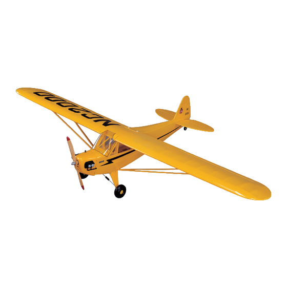
Specifications:
Wingspan:
82.7" (2100mm)
Length:
48" (1215mm)
Wing area:
850 in
2
(55dm
Weight:
6.5-7.5lbs (3-3.5kg)
Engine:
.46-.61 2 Cycle
.50-.91 4 Cycle
Radio:
4 Channel (5 Servos)
Thunder Tiger Piper J-3 Cub ARF Airplane (TTR4532)
Distributed in North America by Ace Hobby Distributors, Inc. • 116 W 19th ST, Higginsville, MO 64037
Phone: 660-584-7121 • www.acehobby.com • E-mail: acehobby@ctcis.net
This kit is guaranteed to be free from defects in material and workmanship at the date of purchase.
It does not cover any damage caused by use or modification. The warranty does not extend beyond the
product itself and is limited only to the original cost of the kit. By the act of building this user-assembled
kit, the user accepts all resulting liability for damage caused by the final product. If the buyer is not
prepared to accept this liability, it can be returned new and unused to the place of purchase for a refund.
This is not a toy. Assembly and flying of this product requires adult supervision.
Read through this book completely and become familiar with the assembly and flight of this airplane.
Inspect all parts for completeness and damage. If you encounter any problems, call 660-584-6724 for help.
Piper J-3 Cub
Assembly Manual
2
)
Notice: Adult Supervision Required
Warranty
1
99206/JE6120
Advertisement
Table of Contents

Subscribe to Our Youtube Channel
Related Manuals for THUNDER TIGER Piper J-3 Cub


Summary of Contents for THUNDER TIGER Piper J-3 Cub
- Page 1 .50-.91 4 Cycle Radio: 4 Channel (5 Servos) Thunder Tiger Piper J-3 Cub ARF Airplane (TTR4532) Distributed in North America by Ace Hobby Distributors, Inc. • 116 W 19th ST, Higginsville, MO 64037 Phone: 660-584-7121 • www.acehobby.com • E-mail: acehobby@ctcis.net Warranty This kit is guaranteed to be free from defects in material and workmanship at the date of purchase.
-
Page 2: Table Of Contents
INTRODUCTION One of the most recognized names in aviation history is the Piper J-3 Cub. A child of the Depression, Mr. Piper’s Cub began production in the early ‘30s, evolving into the 65 HP J-3 version in 1939. Proliferating in the years before and during WWII, the Cub has introduced more young men to the joys of flight than any other airplane ever. -
Page 3: Items Needed Check List
As you will notice, many household tools can be utilized during construction. Engine - The Thunder Tiger PRO-46 and F-54S are the ideal engines for this airplane. These quiet-run- ning engines are easy to start, require no special... -
Page 4: Parts Sketches
PARTS DRAWINGS Fuselage AS6029 Fuel Tank Set #3263 Silicone Tube (1) Clunk (1) Fuel Stopper (1) 90" Nipple (1) Nipple (1) 300 c.c. Tank (1) Fuselage(1) Cap (1) Wing AS6030 Wing Joiner (3) M2mm x 8mm Screw (8) Wing Bolt Plate (1) Hatch (2) Trim Tape (1) Left Wing (1) - Page 5 PARTS DRAWINGS...
-
Page 6: Wing Assembly
WING ASSEMBLY Identify the right and left wing panels. Carefully remove the tape With the right wing panel once again upside down on the building that temporarily secures the ailerons to each wing panel. board, determine the aileron servo location (2nd wing bay in from the inboard edge of the aileron). - Page 7 WING ASSEMBLY Insert a piece of piano wire through the root rib of the wing panel Place the servo hold down plate over the servo and drill through and “fish” the aileron servo lead through the wing. (Photos 9 & 10) the plate into the servo mount taking caution not to drill through the wing.
- Page 8 WING ASSEMBLY Place the control horn on the aileron and align with the servo Locate the three wing joiners (2 plywood and 1 aluminum). Apply horn slot in the hatch cover. Drill holes using the control horn as a a coat of 5-10 Minute Epoxy to each side of the aluminum joiner and template.
- Page 9 WING ASSEMBLY Apply 30-45 Minute Epoxy to the left wing panel spar box as well Place the wing on the fuselage. Carefully align the wing ensuring as the entire root rib. Carefully join the two wing panels together. that it is centered on the fuselage. Using a 19/64” (7.4mm) drill bit, Wipe off any excess epoxy.
-
Page 10: Fuselage Assembly
FUSELAGE ASSEMBLY Carefully cut away the covering over the landing gear slot on the Reinstall the landing gear and secure it in place with 4 M3x8 wood bottom of the fuselage. (Photo 30) screws. (Photo 33) Photo 33 Photo 30 Position the preformed landing gear in place. - Page 11 FUSELAGE ASSEMBLY Install the Cub Wheel followed by another 5mm-wheel collar. Carefully bend the mounting plates to a 45-degree angle then Ensure that the wheel collar is even with the edge of the landing gear secure to the fairings with M2.6x6 screws and M2.6 nuts. (Photo 39) axle and secure it in place with the “L”...
-
Page 12: Stabilizer Assembly
FUSELAGE ASSEMBLY/STABILIZER ASSEMBLY Mount the landing gear fairings in place using 4 M3x8 wood Attach the elevator joiner wire to each elevator half with thick CA screws. (Photo 42) or 5 minute epoxy. (Photo 45) Photo 42 Photo 45 Remove the hinges from the horizontal stabilizer and apply a drop of oil to each hinge. - Page 13 STABILIZER ASSEMBLY Temporarily install the horizontal and vertical stabilizers (in that Cut a slot on the leading edge of the rudder. Trial fit the tail wheel order). Using a felt tip pen mark the fuselage location on both the gear wire to the rudder. Cut a notch in the leading edge of the rudder horizontal and vertical stabilizers.
- Page 14 STABILIZER ASSEMBLY ENGINE & FUEL TANK INST. Install the tail wheel and secure in place with the provided wheel Locate the rubber spacer and adjustable engine mount. Hold in collar. (Photo 55) place on the fuselage firewall and verify fit. Mount the rubber spacer and engine mount to the firewall but do not secure it in place at this time.
-
Page 15: Engine & Fuel Tank Installation
4-13/16” from the firewall. Mark the mounting hole locations on the motor mount. (Photo 64) If installing the recommended Thunder Tiger F-54S engine, extend Photo 64 the choke valve wire insuring that it is long enough to clear the cowl- ing. -
Page 16: Radio Installation
RADIO INSTALLATION Install the switch harness as shown. Wrap the battery pack in foam Install the three servos in the radio compartment (throttle, rudder, and install underneath the fuel tank (Photo 68). You may have to and elevator). From the tail facing forward from right to left, the ser- adjust the battery location to obtain the proper CG. - Page 17 RADIO INSTALLATION Install the other end of the throttle push rod in the EZ connector. Mark the other end of the push rod where the “Z” bend is to be Trim off any excess wire (Photo 75). located (Photo 78). Photo 75 Photo 78 Using “Z”...
-
Page 18: Radio Installation
RADIO INSTALLATION Install the rudder push rod using the same steps as for the elevator. Drill a small hole through the fuselage in line with the switch. (Photos 81, 82, and 83) Insert the extension wire through the fuselage and place in the switch. Using needle nose pliers bend the wire to prevent it from coming loose. -
Page 19: Cowl Installation
COWL INSTALLATION You may need to make a cut behind the engine cylinder head to Position the cowl and drill 3 1/16” (1.5mm) holes on both sides allow the cowling to go into place with minimal effort. (Photo 88) (Photo 91). Photo 88-1 Photo 91 Photo 88-2... -
Page 20: Windshield Installation
WINDSHIELD INSTALLATION WING STRUT ATTACHMENT Cut the windshield along the molded cutting line using a pair of Cut a notch in the wing strut at each end. Drill a 5/64” (2mm) hole scissors (Photo 94). at the wing strut notch (Photo 97). Photo 97 Photo 94 Secure the mounting plate as shown with a M3x5 wood screw... -
Page 21: Balance
WING STRUT ATTACHMENT BALANCE Bend the mount plates that attach to the wing at a 25-degree angle Center of Gravity location should be between 4 and 4-1/2” back from so that they are flush with the surface of the wing (Photo 100). the leading edge of the wing. -
Page 22: Flying Hints
R/C flight. If not, we suggest you learn to fly with a trainer Check all control surfaces for possible looseness or deterioration. before attempting flight with the Cub. Thunder Tiger has a large selec- tion of Trainers to choose from. Check with your hobby dealer for his recommendation. - Page 23 TTR1102 Thunder Tiger 4-Way Wrench ACE24020-24030 Ace PowerMaster Starters Thunder Tiger’s lightweight 4-way wrench fits all glow plugs and prop Keep all those fingers on your hands with budget-priced Ace R/C nuts, plus has room to store extras.
- Page 24 Fun Tiger ARC Fun Tigers Wing Span: 47” (1194mm) Wing Area: 696 in2 (44.9dm2) Length: 43” (1092mm) Weight: 4 lbs. (1.8kg) Engine: .40-.50 2-stroke .40-.65 4-stroke Radio: 4 Channel Fun Tiger Extra Copyright 1999 by Thunder Tiger Corporation, all rights reserved.
Need help?
Do you have a question about the Piper J-3 Cub and is the answer not in the manual?
Questions and answers