Table of Contents
Advertisement
THUNDER TIGER CORP. www.thundertiger.com
C 2008
SPECIFICATION:
SPECIFICATION:
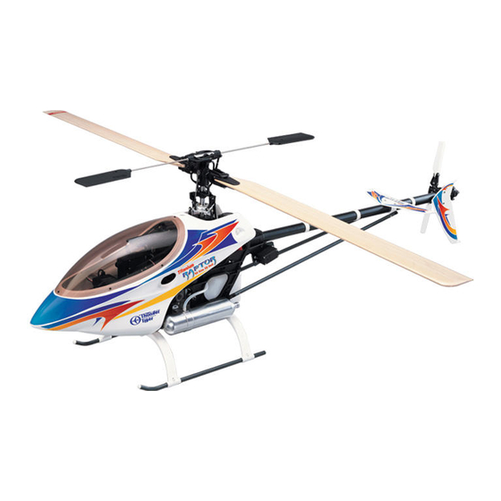
Full length of fuselage:1220mm(48.03")
Full length of fuselage:1200mm(47.24")
Full width of fuselage:140mm(5.51")
Full width of fuselage:140mm(5.51")
Total height:400mm(15.75")
Total height:400mm(15.75")
Main rotor dia:1345mm(52.95") 600mm Blades
Main rotor dia:1345mm(52.95") 600mm Blades
Main rotor dia:1385mm(54.53") 620mm Blades
Main rotor dia:1385mm(54.53") 620mm Blades
Tail rotor dia:237mm(9.33")
Tail rotor dia:237mm(9.33")
Gear ratio:1:8.5:4.56(STD)
Gear ratio:1:8.5:4.56(STD)
Gear ratio:1:8.73:4.56(OP)
Gear ratio:1:8.73:4.56(OP)
Full Equipped weight:3000g (6.6 lbs)
Full Equipped weight:3000g (6.6 lbs)
JK0157 V4
A S S E M B L Y & M A I N T E N A N C E
Advertisement
Table of Contents

Related Manuals for THUNDER TIGER Titan Raptor 50 Size 3D Heli


Summary of Contents for THUNDER TIGER Titan Raptor 50 Size 3D Heli
- Page 1 Gear ratio:1:8.73:4.56(OP) Full Equipped weight:3000g (6.6 lbs) Full Equipped weight:3000g (6.6 lbs) A S S E M B L Y & M A I N T E N A N C E THUNDER TIGER CORP. www.thundertiger.com JK0157 V4 C 2008...
-
Page 2: Table Of Contents
Thunder Tiger design team. The Raptor 50 Titan is more rugged and has improved flying performance than the previous Raptor 50 V2. The Raptor 50 Titan has the best power-to-weight ratio of any 50 class helicopters on the market. - Page 3 FLIGHT SAFETY CHECKLIST 1. Make sure both the transmitter and receiver batteries are fully charged prior to operating the helicopter. 2. Make sure all flight controls operate properly prior to flying. 3. Range check the radio before the first flight. The servos must operate properly with the transmitter antenna collapsed at a range of at least 50 ft.(15 meters).
- Page 4 OTHER ITEMS REQUIRED RADIO SET Switch harness Receiver Battery 1000mAh Gyro Servo x 5 Transmitter (helicopter type only 6 or more channels) ENGINE Fuel Pump Glow Plug 1.5V Glow starter (1.2V~1.5V) HELI ENGINE(50-size) Glow Fuel(15%-30%) 12V Electric starter Foam Extended 6mm Hex Starting Tool 12V Battery Remote Glow Plug...
-
Page 5: Assembling Section
ASSEMBLING SECTION Most parts in the Raptor kit are packed according to the assembly steps. The part number and quantity contained in each step are always shown in the square box on each page. Do not open all the bags at once. Open only the bag that is needed for the current assembly step. - Page 6 1 Fuel Tank Assembly Note: After assembly, check to make sure the Fuel Tank It might be necessary to inspect and replace the silicone clunk can move from top to bottom without touching the tube inside the tank every month to ensure the fuel back of tank.
- Page 7 3 Main Frame Assembly-Part1 Please insert the frame spacers, bearings, pulley and parts in the frames according the drawing below. Install four metal aluminum frame spacers beside the main shaft bearings. Remember add Loctite when securing on these four spacers. Tighten the screws snugly, but do not over torque them which could strip the plastic. Insert starter shaft thr ough the center of the clutch bell assembly, through the top starter shaft bearing and into the starter coupling.
- Page 8 4 Main Drive Gear Assembly It is necessary to add grease inside the one way clutch before your first flight. The clutch might lock up once grease is gone. The one way grease( PV0517) or Ball differential grease is recommended for this lubrication.
- Page 9 6 Main Frame Assembly-Part2 Please complete subassemblies 6-1 through 6-4, them add them to the main frame. Insert the completed elevator control arm subassembly 6-1 in between upper bearing frame first. Then fit the plastic pitch control frame subassembly. Next insert elevator arm control shaft and elevator parallel lever subassembly.
- Page 10 6-1 Elevator Control Arm Subassembly (1)BK0018 Elevator Control Arm....1 (2)BK0023 Elevator Control Arm Link... 2 (3)BK0084 Pin..........2 INSTALLATION OF THE RODS Big Hole Big Hole 6-2 Elevator Push Pull Lever Subassembly (1)BK0836 Elevator Push Pull Lever..... 1 (2)HMV740ZZY Bearing (d4xD7x2.5)... 2 (3)BK0075 Linkage Ball.........
- Page 11 7 Main Frame Assembly-Part3 Insert main shaft through the shaft bearings making sure that the end with the holes closest to the end is pointed down. Next, slide main gear assembly into position on the shaft and line up the holes in the main shaft with the holes in one way clutch shaft of the main gear assembly.
- Page 12 Engine Mount Notes: The engine mount furnished will accommodate the Thunder Tiger 50H, and the other heli engines. If you are installing a Thunder Tiger engine, you will find the mount is wider than the engine crankcase. Two spacers are furnished to accurately locate the engine while bolting it in place.
- Page 13 11 Main Rotor Head Assembly Secure the linkage ball on the Main Rotor Pitch Housing first then insert the Flap Damper in the Main Rotor Hub. Add Silicon Oil or Vaseline to insert the Feathering Shaft through the Flap Dampers. There is also an optional red 80 degree durometer hard damper PV0382 for 3D flying.
- Page 14 12 Flybar Assembly Begin by attaching six Linkage Balls to the Flybar Control Arm and Mixing Lever with Self Tapping Screw. Slide Flybar Arm Bushing and Flybar Control Arm onto the Flybar Rod. From the other end of the Flybar Rod, slide on the Flybar Seesaw Hub.
- Page 15 13 Main Frame Assembly-Part5 Slide the main rotor assembly over the main shaft and align the two pins to slide in the washout assembly. Make sure the holes in the main shaft line up with the holes in the main rotor head. Insert the socket screw and secure with locknut.
-
Page 16: Warning
14 Tail Unit Assembly Secure the tail rotor hub(#11) on tail rotor shaft first, note the Set Screw(#3) should be right setting on the dot of the shaft. Do not forget to apply Loctite on the Set Screws. Do not over tighten the locknut(#4) with the two bearings. Next work on the housing assembly, use care to install the Tail Pitch Control Link, do not over tighten the selftapping Screw(#2). -
Page 17: Hse3-12B Self Tapping Screw (M3X12)
16 Tail Boom Assembly Assembly Tip: Slide the 3 rod guides onto the boom and space them out evenly as shown. Then slide the tail linkage rod into the rod guides. Next, insert the tail rotor drive belt into the boom so that it comes out of both ends. Place drive belt over tail drive pulley and complete balance of tail boom assembly. - Page 18 17 Main Frame Assembly-Part6 Insert the M3x20 and two M3x25 socket screws with meatal Rear Servo Plate into the tail base of the Main Frame and secure with lock nuts. Do not tighten at this point. Hold the tail boom in one hand and hook your index finger on your free hand through the exposed loop of the tail rotor drive belt.
-
Page 19: Hme4-5B Set Screw (M4X5)
18 Servo Installation-Part1 Assembly Tip: Remove all the servo wheels prior to attaching the steel linkage balls. Make sure all linkages are the correct length. (1)HSE2612N Self Tapping Screw(M2.6x12)..4 (10)BK0833 Servo Block........2 (2)HSE2620N Self Tapping Screw(M2.6x20)..4 (11)BK0840 SUS Linkage Rod (M2.3x46)..2 (12)BK0843 SUS Push Rod A......1 (3)BK0075 Linkage Ball........5 (4)BK0086 Ball Link..........9... - Page 20 19 Servo Installation-Part2 Assembly Tip: Remove all the servo wheels prior to attaching the steel linkage balls. Make sure all linkages are the correct length. See Engine-Throttle Control Linkage in page 22. (1)HSE2612N Self Tapping Screw(M2.6x12)..8 (2)HSE2620N Self Tapping Screw(M2.6x20)..4 Mount the Steel Link (3)BK0104 Servo Mounting Plate.......4 Ball at 10.5mm(approx...
- Page 21 20 Receiver/Gyro Installation Thunder Tiger recognizes that there are many brands of radios and gyros to choose from. You are encouraged to seek the advice of experienced helicopter pilots when making this decision. (1) BE1052 Antenna Tube....1 (2) BK0106 Double Side Tape.... 2...
- Page 22 For F3C or 3D flying, we strongly recommend using Carbon or Fiberglass rotor blades for safety and higher performance. Important-While Thunder Tiger takes great care to manufacture the most balanced blades available, no two rotor blades are exactly the same. It is highly recommended that you purchase a blade balancer from your hobby dealer.
- Page 23 Engine Throttle Control Linkage Mount the steel linkage ball to the outer hole on the plastic throttle arm. At full throttle stick, the carburetor hole should open completely. At low throttle and with the throttle trim all the way down, the carburetor hole should close completely.
-
Page 24: Linkage Set-Up Section
LINKAGE SET-UP SECTION... - Page 25 Setting up Main Rotor Blades Pitch Angle On the left side frame, there are three pitch scales molded onto the plastic frame. The three different scales are designed for beginner, intermediate or expert F3C and 3D pilots. For Beginners Use the "pointer" on the collective tray and the plastic molded scales For Intermediates to set up the initial collective...
- Page 26 Setting up Main Rotor Blades Pitch Angle (Hint for beginners) Pitch Push Pull Lever Adjustment 5.5˚ Mount the Steel Linkage Ball at 20mm from the FUTABA center of the Pitch Push Pull Lever. Throttle Stick in the center position The hoveing pitch angle should be at 5.5˚. To get the -2˚ to 11˚...
- Page 27 *High End Blade Pitch Setting 11˚ 11˚ 6˚ -2˚ Linkage Position for beginner -5˚ -10˚ Throttle at High Position *Move the throttle/collective stick to the full throttle position(see upper right diagram). The molded "pointer" should now line up with the upper limit mark, which should provide about 11˚ of blade pitch. *Low End Blade Pitch Setting -2˚...
- Page 28 Collective Travel for F3C and 3D Flying *To achieve +11˚ to -10˚ of collective travel range, the steel linkage ball must be moved to the inner location as shown in the figure. *You can also flip the pitch servo to get the best configuration. *Use ATV function of the transmittler to get the necesary servo travel.
- Page 29 CONFIGURING THE RAPTOR FOR 3D 5-Point Throttle Curves Normal 30 50 75 100 Idle-up1 100 85 60 85 100 Idle-up2 100 60 55 80 100 5-Point Pitch Curves Normal 38 55 75 Idle-up1 22 46 70 Idle-up2 22 46 70 Hold 38 55 75 100 Blade Pitch Angles (degrees)
- Page 30 Radio and Control Linkage Setup For Raptor 50 The performance of any RC helicopter and how well it fly depends strongly on well the model has been set up. We will go through the step-by-step on how to set up the transmitter and mechanics linkages to make your Raptor 50 fly at its best.
- Page 31 1700 to 1800 for good 3-D flying. We recommend using only carbon graphite main rotor blades for aggressive 3-D flying. Please try the Thunder tiger 600 mm carbon graphite rotor blades, they are designed for extreme 3-D flying with the Raptor 50. Wood main rotor blades are fine for learning how to fly or for practicing simple maneuvers.
- Page 32 Radio and Control Linkage Setup For Raptor 50 4.Tail Rotor Control and Gyro Setup The radio setup for using a heading hold gyro and a non-heading hold gyro will be different. But the mechanical setup will be the same. Heading Hold Gyro Setup: Set the tail rotor mixing or revolution mixing values to zero for every throttle mode in the transmitter.
-
Page 33: Blade Modification
Blade Modification Idea and original art submitted by Randy Wishon, Progressive Technologies, inc. 1. Mark around blade grips with a felt-tip marker. 2. Remove blade grips and cut covering lightly .125” inside of mark, being careful not to cut into the blade. 3. - Page 34 After Flight Checklist (1) Check every screw and bolt to make sure none has loosened due to vibration. (2) Check every rotating and movable part to ensure they still move smoothly and normally. (3) Clean off the exhaust residue from the muffler, engine, and helicopter. (4) Check all movable parts, such as gears, ball links, belt, etc.
-
Page 35: Parts List Section
PARTS LIST SECTION... - Page 36 PV0451 Harden Main Shaft AK0148 85T Main Spur Gear PV0520 686XL Tail Drive Belt AV0052 Tail Idel Pulley Assy. AV0143 Cooling Fan Assy. PV0002 Flybar Control Arm PV0004 Mixing Lever PV0005 Flybar Control Rod PV0012 Pitch Control Arm PV0013 Elevator Arm PV0014 Elevator Lever PV0015...
- Page 37 PV0033 Servo Frame PV0035 Landing Skid Set(AL) PV0036 Flybar Paddle PV0037 Tail Rotor Blade PV0035-T Landing Skid Set(Titan) PV0038 Tail Fin PV0040 Double Link PV0041 Ball Link PV0048 Pitch Frame/Rotor Hub Seesaw Brg. PV0049 Seesaw Brg. PV0051 Lever Brg. PV0052 Tail Slider Brg.
- Page 38 PV0093 Main Shaft Brg. PV0107 Engine Mount (.50) PV0109 High Performance PV0148 Tail Rotor Grip Muffler (.46~.50) PV0118 600mm Wood Main Rotor Blades PV0151 Tail Rotor Hub PV0639 Tail Rotor Angular Brg. PV0203 Starter Shaft Brg. PV0267 Loctite #242 PV0268 Loctite #262 PV0270 Grease (For Bearing) PV0279 Tail Rod Guide PV0311 Header Tank...
- Page 39 PV0361 Starter Coupling PV0363 Fuel Tank PV0364 Body(White) PV0364-Y Body(Yellow) PV0365 Thrust Brg. PV0532 Clutch Liner PV0370 Body Only(White) PV0372 Thrust Collar PV0370-Y Body Only(Yellow) PV0374 Feathering Brg. PV0375 Body Retaining Set PV0379 Auto Rotation Pully PV0373 Clutch Bell Brg. PV0519 Rear Servo Rod (R50T) PV0380 Pinion Gear 10T PV0381 70 Durometer Flap...
- Page 40 PV0480 Main Frame Set PV0486 Flybar Seesaw PV0503 Washout Set PV0504 Tail Pitch Slider PV0505 SUS Linkage Rod PV0536 Clutch Bell PV0507 SUS Tail Control Rod PV0508 Decal PV0509 Pitch Push Pull Lever Set PV0510 Elevator Push Pull PV0515 Body Support Lever Set HMC3-10B M3X10 HMF2-6N M2X6...
- Page 41 Reference Parts No. Description Item No. Description quantity Assemble Step AK0148 85T Main Spur Gear BK0148 8ST Main Spur Gear AV0143 Cooling Fan Assy. BV0143 Cooling Fan Assy. PV0002 Flybar Arm BK0002 Flybar Control Arm BK0005 Flybar Arm Bushing BK0075 Linkage Ball HME4-5B Set Screw, M4x5...
- Page 42 Reference Parts No. Description Item No. Description quantity Assemble Step BK0036 Pulley Collar BK0081 Pin, D13xL18 PV0027 Tail Case BK0046 Tail Unit Housing (L) BK0047 Tail Unit Housing (R) HMC3-20B Socket Screw, M3x20 HMC3-25B Socket Screw, M3x25 HMM3Z Lock Nut, M3 PV0029 Tail Pulley Set BK0050...
- Page 43 Reference Parts No. Description Item No. Description quantity Assemble Step HNI3 Hex Wrench 3m/m HNJ-1 Tie Band 2.5x100 PV0062 Body Mount Rubber Grommet BK0102 Body Mount Rubber PV0062-Y Body Mount Rubber Groment BK0102Y Body Mount Rubber PV0092 Metal Swash plate BV0092 Metal swash plate PV0093...
-
Page 44: Bk0594 Starter Coupling
Reference Parts No. Description Item No. Description quantity Assemble Step PV0359 Clutch BK0170 Shim BV0589 Clutch Bell Set HMC3-10B Socket Screw, M3x10 PV0360 Starter Shaft BK0592 Starter Shaft HME4-5B Set Screw, M4x5 HMS5 E-Clip PV0361 Starter Coupling BK0594 Starter Coupling HME4-5B Set Screw, M4x5 PV0363... -
Page 45: Bk0171 Pin
Reference Parts No. Description Item No. Description quantity Assemble Step HSE3-12B Self-Tapping Screw,M3x12 HMM3Z Lock Nut,M3 PV0486 Flybar Seesaw BK0004 Seesaw HMV830ZZ BRG,d3xD8xw4 PV0503 Washout Set BK0014 Washout Base BK0015 Flybar Control Lever BK0016 Washout Linkage BK0075 Link Ball BK0077 Collar (d3xD4xL6) BK0171 HMC3-10B... -
Page 46: Bk0075 Linkage Ball
Reference Parts No. Description Item No. Description quantity Assemble Step PV0510 Elevator Push Pull Lever Set BK0075 Linkage Ball BK0076 Collar (d3xD4xL10) BK0078 Collar (d3xD4xL4) BK0086 Ball Link 8,18 BK0088 Flat Washer BK0104 Servo Mounting Plate BK0833 Servo Block BK0836 Elevator Push Pull Lever BK0845 SUS Linkage Rod (L=64) - Page 47 HELICOPTER ACCESSORIES NO. 3800 BLADE SUPPORT NO. 3801 6MM STARTER NO. 3802 PRECISION NO. 3803 REMOTE GLOW EXTENSION PITCH GAUGE ADAPTER α 8030 ZERO NO. 8070 HEADING LOCK GYRO, TG7000 NO. 8071 TG7000, DS0606 NO. 8126 DIGITAL SERVO, DS1213 GOVERNOR NO.
- Page 48 OPTIONAL PARTS PV0439 M.TAIL Pitch Fork(A1) PV0440 METAL FRAME SPACER PV0399 MAIN ROTOR GRIP POST PV0394 SIM-CARBON CANOPY R30 V2 PV0439-T M.TAIL Pitch Fork(B1) PV0441 METAL ELEVATOR PV0442 METAL MIXING LEVER PV0443 STABILIZER CONTROL PV0444 FLYBAR CONTROL LEVER SET ARM SET PV0445 METAL WASHOUT PV0446 METAL AILERON LEVER PV0447 ELEVATOR ARM LINK...
- Page 49 PV0502 3D FIRERGLASS BODY PV0512-Y SKID DAMPER PV0512-W SKID DAMPER PV0512-L SKID DAMPER (YELLOW) (WHITE) (BLUE) PV0513 METAL PITCH PUSH PV0514 METAL ELEVATOR PV0522 POM FLAP DAMPER PV0518 OPTIONAL GEAR SET PULL LEVER PUSH PULL LEVER PV0523 CARBON TALL BOOM 9605 PRO-50H ENGINE (R50T) HELICOPTER STARTING EQUIPMENT...
Need help?
Do you have a question about the Titan Raptor 50 Size 3D Heli and is the answer not in the manual?
Questions and answers