Table of Contents
Advertisement
INSTRUCTIONS
DP71
MICROSCOPE DIGITAL CAMERA
This instruction manual is for the Olympus Microscope Digital Camera Model DP71. To ensure the
safety, obtain optimum performance and familiarize yourself fully with the use of this camera, we
recommend that you study this manual thoroughly before operating the camera.
For image operations including recording, editing and saving, please refer to the Online Help for
the DP-BSW Basic Software.
Retain this instruction manual in an easily accessible place near the work desk for future reference.
A X 7 7 3 8
This publication is printed on 100% recycled paper
Advertisement
Table of Contents

Related Manuals for Olympus DP71


Summary of Contents for Olympus DP71
- Page 1 DP71 MICROSCOPE DIGITAL CAMERA This instruction manual is for the Olympus Microscope Digital Camera Model DP71. To ensure the safety, obtain optimum performance and familiarize yourself fully with the use of this camera, we recommend that you study this manual thoroughly before operating the camera.
- Page 2 This device complies with the requirements of directive 89/336/EEC concerning electromagnetic compatibility. The CE marking indicates compliance with the above directive. NOTE: This equipment has been tested and found to comply with the limits for a Class A digital device, pursuant to Part 15 of the FCC Rules.
-
Page 3: Table Of Contents
DP71 CONTENTS IMPORTANT — Be sure to read this chapter for safe use of the equipment. — SYSTEM CHART NOMENCLATURE HARDWARE INSTALLATION 8-10 Installing the PCI Interface Board ..........................8 Installing the Camera Head ..............................9 Connecting the Cables ................................10... -
Page 4: Important - Be Sure To Read This Chapter For Safe Use Of The Equipment
IMPORTANT The DP71 microscope digital camera is designed to be connected to a camera adapter mounted on an Olympus UIS2/UIS series of optical microscope for use in recording of microscopic magnified images at high speed (about 3 seconds) and highest resolution while maintaining high picture quality and high color reproduction. - Page 5 2. The computer used with this system should set up and run Microsoft Windows 2000, XP or Vista. For the OS in the computer, the user is requested to create a backup and retain it carefully. (Olympus does not support the matters related to the OS including its backup.)
-
Page 6: Conformity Of The System
A camera adapter with a magnification below 0.5X cannot be used because part of image will be cut off. 2. When the DP71 is connected to the rear port of the U-DPT or U-MPH, the peripheral part of the recorded image may be deteriorated due to the optical performance of the U-DPT or U-MPH. - Page 7 7. Sequential connection of PCI units Up to two PCI units including the DP71 and a PCI interface board of the DP70/DP30BW or FV1000 can be connected in series. However, their simultaneous operation is not available so it is required to select either PCI interface operation.
-
Page 8: Maintenance And Storage
Getting Ready 1. The camera head uses precision components. Handle it with care and avoid subjecting it to a sudden or severe impact. 2. The image displayed on the monitor may be affected when it is used near equipment generating strong electromagnetic waves. -
Page 9: System Chart
DP71 SYSTEM CHART (Note) Microscopes that are not listed in the above may also be applicable. For details, please consult Olympus. -
Page 10: Nomenclature
NOMENCLATURE Any equipment connected to the camera head should be an Olympus-designated product or a Camera Head product in compliance with the requirements of IEC60950 or CISPR22/24. If equipment other than these products is connected, Olympus cannot guarantee any performance of the camera. -
Page 11: Hardware Installation
DP71 HARDWARE INSTALLATION Installing the PCI Interface Board (Figs. 1 & 2) # Before installing the PCI interface board in the computer, be sure to read the instruction manuals for the computer in order not to damage them. # Be sure to turn off the computer and peripherals and unplug their power cords before installing the PCI interface board. -
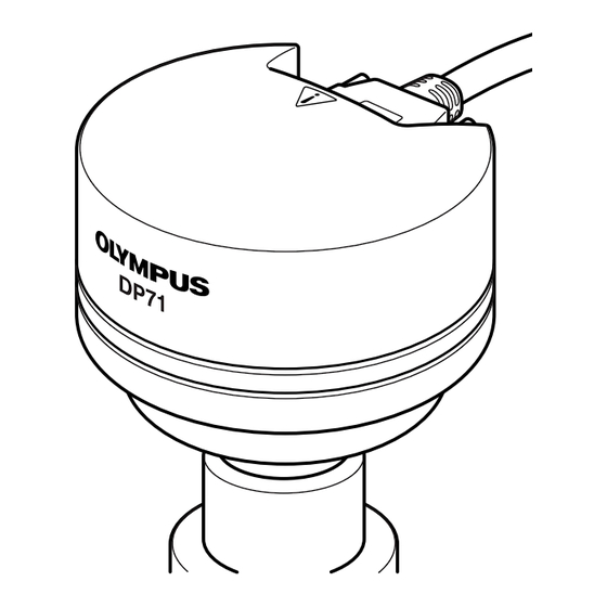
Page 12: Installing The Camera Head
}The DP-TRAD tripod adapter is provided with two types of screws (2 each) and an Allen wrench. Use only the Phillips screws (x 2) with the DP71. 1. Attach the DP-TRAD tripod adapter | to the camera head 5 and clamp them using the provided Phillips screws (x 2) with a Phillips screwdriver. -
Page 13: Connecting The Cables
Be sure to switch off the computer before proceeding to the connections. Always use the cables designated by Olympus. ² Connecting the Interface Cable 1. Connect the connector @ on one end of the interface cable to the connector ²... -
Page 14: Software Installation
SOFTWARE INSTALLATION }This chapter describes the installation of the optionally available DP-BSW Basic Software for DP71. Before Installation When the OS is Windows Vista or Windows The software cannot be installed unless the user account is registered as “computer administrator.”... - Page 15 [Next] button. a) DP71/DP70/DP30BW Application Program Checking this installs the application, which allows you to control the DP71 for recording images and manage the images in a simplified manner using thumbnails. b) DP71/DP70/DP30BW TWAIN...
- Page 16 14. When the [Windows Security] dialog box appears, then click 19. Click on [System]. on the [Install] button. 15. When the installation completes, the window below appears. Then click on the [Finish] button. 20. Click on the <Device Manager> button in the “Tasks". 16.
-
Page 17: Windows Xp, Windows
[Next] button. a) DP71/DP70/DP30BW Application Program Checking this installs the application, which allows you to control the DP71 for recording images and manage the images in a simplified manner using thumbnails. b) DP71/DP70/DP30BW TWAIN Checking this installs the program, which allows you to 8. - Page 18 12. The [Select Program Folder] window appears. If you want to 14. When the installation completes, the window below ap- change the program folder, change the name under pears. Then click on the [Finish] button. [Program Folders] or select a folder under [Existing Folders]. Then click on the [Next] button.
- Page 19 DP71 18. Click on [System]. 19. When the [System Properties] dialog box is displayed, click on the [Hardware] tab and then click on the <Device Man- ager> button. 20. If the driver has been properly installed, “MalAd Device" should be displayed as shown below. After confirming this, click on the <...
-
Page 20: Image Recording Procedure
IMAGE RECORDING PROCEDURE (Notes) The encircled numbers indicate the control positions in the windows shown on the next page. For detailed operating procedures, refer to the Online Help for the DP Controller and DP Manager. Brightfield Observation Fluorescence Observation Launch DP Manager. Launch DP Manager. -
Page 21: Displayed Windows
Camera icon * Folder bar Thumbnail bar Status bar Window display area * The camera name shown on the camera icon is the last camera name used with the DP Controller. The camera name shown immediately after installation may be “DP71/DP70/DP30BW.”... -
Page 22: External Triggering
EXTERNAL TRIGGERING }The DP71 can record still images or control a commercially available shutter based on an external trigger signal. Trigger Input · The trigger input from external equipment can be used to start still image recording using the DP-BSW. - Page 23 DP71 Trigger Output · The trigger output can be used to control a commercially available shutter. · The positive and negative logics of the trigger output can be switched with the DP Controller. · The trigger output is interlocked with the shutter release/close operations of the DP Controller.
-
Page 24: Specifications
SPECIFICATIONS DP71 Specifications Item Specifications Camera system Single-CCD color camera (pixel shifting). Image pickup device 2/3-inch color CCD. Total pixels: 1.5 million pixels. Effective pixels: 1.45 million pixels. Pixel pitch: 6.45 μm (H) x 6.45 μm (V). Scanning method: Progressive scanning. - Page 25 DP71 Item Specifications Image accumulation* Modes Integral, averaging Accumulation count 64 frames (max.) White balance Modes* Area-specified auto, Entire area-specified auto, Manual Black balance Modes* Area-specified auto, Entire area-specified auto, Manual Contrast modes* Low, Standard, High, Linear. Sharpness filter* Low, Standard, High.
-
Page 26: Troubleshooting Guide
Under certain conditions, the performance of the camera may be adversely affected by factors other than defects. If problems occur, please review the following list and take remedial action as needed. If you cannot solve the problem after checking the entire list, please contact Olympus for assistance. Problem... - Page 27 DP71 Problem Cause Remedy Page f) Picture is too dark. Exposure correction is set in the - Return the exposure correction value (Online direction. to 0 and set the desired exposure manual) correction value. The metering area is set to a bright area...
-
Page 28: Software Uninstallation
1. Click on the [Start] button and select [Control Panel]. 2. Click on [Uninstall a Program] under [Programs]. 3. When the [Uninstall or change a program] window appears, select [OLYMPUS MICRO DP71/DP70/DP30BW] and click on the [Uninstall] button. 4. When the [User Account Control] dialog box appears, click on the [Continue] button. - Page 29 MEMO...
- Page 30 MEMO...
- Page 32 Shinjuku Monolith, 3-1, Nishi Shinjuku 2-chome, Shinjuku-ku, Tokyo, Japan Postfach 10 49 08, 20034, Hamburg, Germany 3500 Corporate Parkway, P.O. Box 610, Center Valley, PA 18034-0610, U.S.A. One Corporate Drive, Orangeburg, NY 10962, U.S.A. 491B River Valley Road, #12-01/04 Valley Point Office Tower, Singapore 248373 31 Gilby Road, Mount Waverley, VIC., 3149, Australia 5301 Blue Lagoon Drive, Suite 290 Miami, FL 33126, U.S.A.
Need help?
Do you have a question about the DP71 and is the answer not in the manual?
Questions and answers