
Related Manuals for J-Power Grob 120TP


Summary of Contents for J-Power Grob 120TP
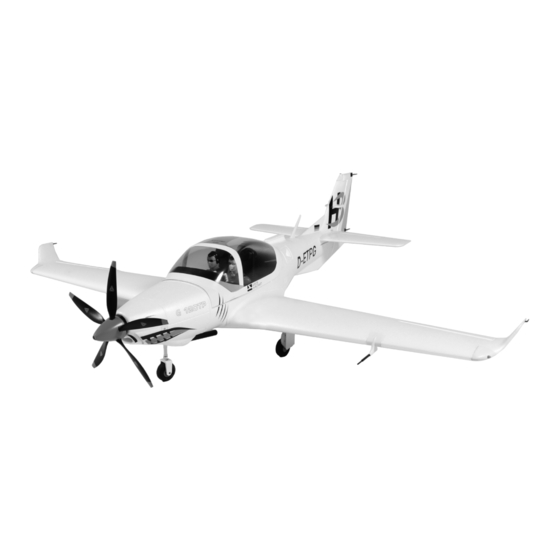
- Page 1 Assembly and Operating Manual Grob 120TP Specification: *Length:51‐2/5"(1305mm) *Wing span: 66‐9/10"(1700mm) *Flying weight: 2800g(98-4/5oz.)
- Page 2 2.4 GHz systems. factory-assembled model aircraft from the and servo. J-POWER LIGHT PLANE RANGE and thank you The receiving system is powered by the speed Integral wing panels with L.H / R.H. ailerons and for placing your trust in us.
- Page 3 Assembly and Operating Manual Grob120TP Figs. 1 -Picture shows the elevator surface ,control horns and hinges .Assemble the control horns and hinges to the elevator . Figs. 2 - Cut up the elevator, drill hole in the location of install hinges. Fig.
- Page 4 Assembly and Operating Manual Grob120TP Fig. 5 -Assemble the elevator to fuselage ,and screw up it . Fig. 6 -Cut up the rudder , drill hole in the location of install hinges Fig. 7 -Assemble the hinges to the rudder surface Fig.
- Page 5 Assembly and Operating Manual Grob120TP Fig. 9 -Fixed the vertical with screw . Fig. 10 -Assemble the vertical to the fuselage . Figs. 11 -Heat the shrink tube .to avoid the collet chuck loosen Figs. 12 - Cut up the rudder , drill hole in the location of install hinges...
- Page 6 Assembly and Operating Manual Grob120TP Figs. 13 -Assemble the hinges to the aileron . Figs. 14 -Photo shows the hinges have settled in the aileron . Figs. 15 -Photo shows the main wing support wood board.. Figs. 16 -Apply glue to the board .Assemble the board to the main wings.
- Page 7 Assembly and Operating Manual Grob120TP Figs. 17 -Photo shows the main wing support bar have installed in the wings . Figs. 18 -Assemble the control rods to the left and right main wings. Figs. 19 - Assemble the control rods to the left and right aileron Figs.
- Page 8 Assembly and Operating Manual Grob120TP Figs. 21 - Assemble the propellers and spinner cover with screws . Figs. 22 -Photo shows the propellers connected on the cover . Figs. 23 -Assemble the propellers on the motor . Figs. 24 -Photo shows the finished view.
- Page 9 Assembly and Operating Manual Grob120TP Figs. 25 -Assemble the spinner to the spinner cover .lock it with screw . Figs. 25 -Photo shows the accessories Figs. 27 -Assemble accessories A,C and G to the Vertical fin . Figs. 28 -Assemble accessories D,H and E to the fuselage .
- Page 10 Assembly and Operating Manual Grob120TP Figs. 29 -Assemble the accessory B to the nosing of the plane . Figs. 30 -Assemble the accessory F to the main wing . Figs. 31 -Assemble the accessory I to the main wing . Figs.
- Page 11 Assembly and Operating Manual Grob120TP Figs. 33 - Congratulations, have completed assembly process. We hope you enjoy flying your new model! Figs. 34- Photo shows the balancing weight. - Place the canopy on the fuselage. - Place the battery in the model of balancing; do not connect it.
- Page 12 Assembly and Operating Manual Grob120TP Fig.35 Charge the flight battery; connect the Equalizer lead using and adapter lead matching your charger (adapter lead not included). Fig.36 - Switch the transmitter on, and move the throttle stick to the “Motor OFF” position. (Diagram MODE 1 right throttle control stick)
- Page 13 Assembly and Operating Manual Grob120TP Fig.37-40 Function test - Check the channel assignment at the receiver, and if necessary swap the plugs as necessary. - Set the transmitter sticks and trims to centre. - The control surfaces should now also be at centre (neutral). Adjust the clevis where necessary.
- Page 14 Assembly and Operating Manual Grob120TP Fig. 41 checking the electric power system - Caution: position the throttle stick in such a way that the motor cannot possibly start running.
- Page 15 Assembly and Operating Manual Grob120TP - Switch the transmitter on, and connect the - With the motor running at full-throttle, give the Test-flying, flying notes flight pack Check the direction of rotation of aeroplane a firm launch directly into any breeze, Read the sections in the Safety the motor: when viewed from the front, the with the fuselage and wings level.
- Page 16 Assembly and Operating Manual Grob120TP J-POWER GROUP CO.,LTD 5th Floor, A3 Building, Xinjianxing Technology Industrial Park, Fengxin Road, Guangming Town, Bao'an, Shenzhen City, 518107 China Phone: +86 755 33699201 Fax: +86 755 33699203 www.jpower.hk...
Need help?
Do you have a question about the Grob 120TP and is the answer not in the manual?
Questions and answers