Black Horse Model BH150 Instruction Manual Book
Hide thumbs
Also See for BH150:
- Instruction manual book (21 pages) ,
- Instruction manual book (49 pages)
Table of Contents
Advertisement
Quick Links
Instruction Manual Book
Item code: BH150.
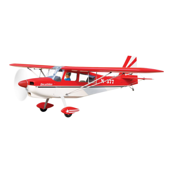
SUPER DECATHLON
ALL BALSA - PLY WOOD CONSTRUCTION.
COVERED WITH ORACOVER.
95% ALMOST READY TO FLY
SPECIFICATION
Wingspan: 2,450mm (96.46in).
Length: 1,750mm (68.90in).
Weight: 7.5kg (16.50lbs).
Wing area: 97dm
.
2
Wing loading: 77g/dm
.
2
Wing type: Naca Airfoil.
Spinner: 86mm.
Gear type: Aluminium Hi-grade for main gear and tail gear (included).
Parts listing required (not included).
Engine: O.S GT 33 cc Gas.
Radio: 05 channels.
Servo: 06 standard high torque servos. Size: (40x20x38) mm.
Made in Vietnam.
Advertisement
Table of Contents

Related Manuals for Black Horse Model BH150


Summary of Contents for Black Horse Model BH150
- Page 1 Instruction Manual Book Item code: BH150. SUPER DECATHLON ALL BALSA - PLY WOOD CONSTRUCTION. COVERED WITH ORACOVER. 95% ALMOST READY TO FLY SPECIFICATION Wingspan: 2,450mm (96.46in). Length: 1,750mm (68.90in). Weight: 7.5kg (16.50lbs). Wing area: 97dm Wing loading: 77g/dm ...
-
Page 2: Parts Listing
SUPER DECATHLON Item code: BH150. Instruction Manual This instruction manual is designed to help you build a great flying aeroplane. Please read this manual thoroughly before starting assembly of your SUPER DECATHLON. Use the parts listing below to identify all parts. -
Page 3: Safety Precaution
SUPER DECATHLON Item code: BH150. Instruction Manual Caution: This model is not a toy! This model is highly pre-fabricated and can be built in If you are a beginner to this type of powered model, a very short time. However, the work which you have to please ask an experienced model flyer for help and carry out is important and must be done carefully. -
Page 4: Installing The Aileron Servos
SUPER DECATHLON Item code: BH150. Instruction Manual REPLACEMENT SMALL PARTS 4x20mm 4x20mm 5x50mm 3x8mm 3x35mm 3x10mm 3x30mm 3x15mm 3x15mm 4x15mm 1. Aluminium landing gear. 2. Wheel pants. 3. Wheels. 4. Plywood of wing struts. 5. Aluminium tube of wing struts. -
Page 5: Installing The Aileron Linkages
SUPER DECATHLON Item code: BH150. Instruction Manual 2. INSTALLING THE AILERON CONTROL HORN 1) Remove the covering from the slot on the bot- Secure tom of the aileron. 2) Insert the control horn into the slot and secure it by A+B Epoxy glue. -
Page 6: Installing The Wing Strut
SUPER DECATHLON Item code: BH150. Instruction Manual Repeat the procedure to install the opposite wing half. II. INSTALLING THE WING STRUT See pictures below 3x8mm Secure 69.5mm 71.2mm 3x6mm Bend Secure Secure 3x8mm Secure Secure 3x10mm 3 x 8mm 111mm... -
Page 7: Installing The Engine Mount
SUPER DECATHLON Item code: BH150. Instruction Manual IV. FUEL TANK 1. INSTALLING THE STOPPER ASSEMBLY 1) The stopper has been pre-assembled at the factory. 2) Using a modeling knife, cut one length of silicon fuel line (the length of silicon fuel line is calculated by... -
Page 8: Installing The Throttle - Cable
SUPER DECATHLON Item code: BH150. Instruction Manual 7) Using a modeling knife, cut 3 lengths of fuel line 150mm long. Connect 2 lines to the 2 vent tubes and 1 line to the fuel pickup tube in the stopper. -
Page 9: Installing The Canopy
SUPER DECATHLON Item code: BH150. Instruction Manual Top side Bottom side Secure Trim and cut Connector Servo arm 1) Slide the fiberglass cowl over the engine and line up the back edge of the cowl with the marks you made on the fuselage. -
Page 10: Installing The Spinner
SUPER DECATHLON Item code: BH150. Instruction Manual Drill four 2.5mm pilot holes through both the cowl and the side edges of the firewall. Using a 3mm drill bit, enlarge the four holes in the cowling. 3 x 12mm Push in... -
Page 11: Elevator Installation
SUPER DECATHLON Item code: BH150. Instruction Manual ELEVATOR CONTROL HORN IX. ELEVATOR INSTALLATION AND PUSHROD INSTALLATION 1) Install the rubber grommets and brass collets into the elevator servo. Test fit the servo into the servo tray. 2) Mount the servo to the tray using the mounting screws provided with your radio system. -
Page 12: Rudder Cable Installation
SUPER DECATHLON Item code: BH150. Instruction Manual X. RUDDER INSTALLATION 1. RUDDER CONTROL HORN INSTALLATION 1) Remove the covering from the slot on the bot- Please see pictures below. tom of the rudder. 2) Insert the control horn into the slot and secure it by A+B Epoxy glue. -
Page 13: Rudder Servo Installation
SUPER DECATHLON Item code: BH150. Instruction Manual 3. RUDDER SERVO INSTALLATION Rudder servo install as same as method of elevator servo. Mark and Drill a hole 2mm Rudder servo Secure Secure XI. MOUNTING THE TAIL WHEEL 3x35mm BRACKET 3x10mm 3x15mm... - Page 14 SUPER DECATHLON Item code: BH150. Instruction Manual Secure Secure Top side Bottom side XII. MAIN GEAR INSTALATION Bottom side PARTS REQUIRED 4x20mm 4x20mm 5x50mm Top side 1) Assemble and mounting the wheel pants as shown in the following pictures.
-
Page 15: Installing The Switch
SUPER DECATHLON Item code: BH150. Instruction Manual XIII. INSTALLING THE SWITCH 1) Cut out the switch hole using a modeling knife. Use a 2mm drill bit and drill out the two mounting holes through the fuselage side. 2) Secure the switch in place using the two machine Flat washer. -
Page 16: Installing Cockpit Fuselage
SUPER DECATHLON Item code: BH150. Instruction Manual Battery of engine Secure Battery receiver XVI. INSTALLING COCKPIT Receiver FUSELAGE See picture below: XV. INSTALLING THE WING STRUT BRACKET 4x15mm... - Page 17 SUPER DECATHLON Item code: BH150. Instruction Manual Push on Push on 3x15mm Secure A/B Epoxy glue. Push on Pillot A/B Epoxy glue. Secure...
-
Page 18: Wing Attachment
SUPER DECATHLON Item code: BH150. Instruction Manual Attach the aluminium tube into the fuselage. Fuselage Push on Push in Insert two wing panels as pictures below. 1. Push in Secure XVII. WING ATTACHMENT Locate the aluminium wing dihedral brace. Aluminium tube. - Page 19 SUPER DECATHLON Item code: BH150. Instruction Manual 3x15mm BALANCING 1) It is critical that your airplane be balanced cor- rectly. Improper balance will cause your plane to lose control and crash. THE CENTER OF GRAVITY IS LOCATED 108MM BACK FROM THE LEADING EDGE OF THE Secure WING.
-
Page 20: Control Throws
SUPER DECATHLON Item code: BH150. Instruction Manual CONTROL THROWS 1) We highly recommend setting up a plane using the control throws listed. 2) The control throws should be measured at the widest point of each control surface. 3) Check to be sure the control surfaces move in the correct directions. - Page 21 I/C FLINGT WARNINGS Always operate in open areas, away adjust the engine from ALWAYS from factories, hospitals, schools, NEVER fly near power lines, behind the propeller, and do not buildings and houses etc. NEVER aerials or other dangerous areas allow any part of your body to be in fly your aircraft close to people or including airports, motorways etc.
Need help?
Do you have a question about the BH150 and is the answer not in the manual?
Questions and answers