Table of Contents
Advertisement
Advertisement
Table of Contents

Related Manuals for Carrier ETN


Summary of Contents for Carrier ETN
-
Page 1: Installation Instructions
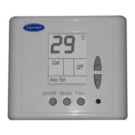
NON-PROGRAMMABLE THERMOSTAT « ETN » Installation instructions Electrical Handling and Connecting 2 2 2 2 2 9 9 9 9 9 Cool Auto Fan Order no.: AM036948 - October-05. Replacing order no.: New Code XK01J010N The manufacturer reserves the right to make any modifications without prior notice. - Page 2 ALARMS: INTERCONNECTION BETWEEN THE THERMOSTAT AND THE UNITS WITH MASTER LINK-I Please read this manual carefully before installaton and use ONLY VALID FOR WIRING DIAGRAMS: REF.-ETN01-02-03-04-05-06-07-08-13-14-15 AND 16 FREE VOLTAGE CONTACT UNITS FREE VOLTAGE CONTACT UNITS CONTENTS AND ELECTRICAL HEATERS 1.- General features and Accessories.
- Page 3 ALARMS: INTERCONNECTION BETWEEN THE THERMOSTAT AND THE UNITS WITH MASTER LINK-I ONLY VALID FOR WIRING DIAGRAMS: REF.-ETN01-02-03-04-05-06-07-08-13-14-15 AND 16 UNITS WITHOUT ELECTRICAL HEATERS UNITS WITH ELECTRICAL HEATERS Remove rear panel. Pass the connection wiring through the hole marked with . Secure the rear panel to a standard recessed PA1/PA2 PA1/PA2 box using the two screws marked with or...
-
Page 4: Thermostat Terminals
MICROS BLOCK S2 Micro No. Micro No. 1 - 3 - 4 - 5 - 6 1 - 3 - 4 - 5 - 6 O F F O F F Position Position REF.- ETN.17 05-05-05 - 4 - - 33 -... - Page 5 14.5 Micro No. Micro No. 1 - 3 - 4 - 5 - 6 1 - 3 - 4 - 5 - 6 O F F O F F Position Position REF.- ETN.16 10-06-05 - 32 - - 5 -...
-
Page 6: Terminal Blocks
Micro No. 1 - 3 - 6 O F F O F F Position Position ¡IMPORTANT! Before making any modification to the Micro-switches, REF.- ETN.15 disconnect any power to the air conditioning unit. 10-06-05 - 6 - - 31 -... - Page 7 Position Position Each micro-switch can be set to ON or OFF. 1 2 3 4 5 6 REF.- ETN.14 Example micros 1 and 6 to ON and micros 2, 3, 4 and 5 to OFF 10-06-05 - 30 - - 7 -...
-
Page 8: On-Screen Display
ON-SCREEN DISPLAY 1-3-4-5-6 2 - 4 - 5 Micro No. Micro No. 1 - 3 - 6 O F F O F F Position Position Set Temp. REF.- ETN.13 Atmospheric or return temp. 10-06-05 - 8 - - 29 -... - Page 9 Reconnect the 24 vac. power supply. · Use shielded-type wiring to connect the sensor. MICROS BLOCK S1 MICROS BLOCK S2 1-3-4-5-6 Micro No. Micro No. 1-3-4-5-6 O F F O F F Position Position REF.- ETN.12 10-06-05 - 28 - - 9 -...
- Page 10 OPERATING MANUAL UNIT ELECTRICAL BOX TERMINALS TECHNICAL ADJUSTMENT (Heat pump Models) MICROS BLOCK S1 MICROS BLOCK S2 1-3-4-5-6 Micro No. Micro No. 1-3-4-5-6 O F F O F F Position Position REF.- ETN.11 10-06-05 - 10 - - 27 -...
-
Page 11: Non-Programmable Thermostat
2 - 4 - 5 Micro No. Micro No. 1 - 3 - 6 O F F O F F Position Position REF.- ETN.10 On / Off M o d e F a n 10-06-05 - 26 - - 11 -... - Page 12 O F F O F F Position Position fans are working. REF.- ETN.09 On / Off M o d e F a n 10-06-05 - 12 - - 25 -...
- Page 13 Position Position On / Off M o d e F a n taking the temperature limits into account, although the thermostat REF.- ETN.08 will work according to the settings established (Sections 7.1 and 7.2) 05-05-05 - 24 - - 13 -...
- Page 14 Position ) button and UL (unlocked) will appear on The press the ( REF.- ETN.07 On / Off M o d e F a n This Unit can exceptionally be configured as Cooling only, despite it including a Heat screen.
- Page 15 Unit has been solved, the thermostate will automatically return to its O F F O F F Position Position operating mode. On / Off M o d e F a n REF.- ETN.06 No alarm is displayed when the thermostate is switched «OFF». 05-05-05 - 22 - - 15 -...
- Page 16 MICROS BLOCK S2 1-3-4-5-6 2-4-5 Micro No. Micro No. 1-3-6 O F F O F F Position Position REF.- ETN.05 This Unit can exceptionally be configured as Cooling only, despite it including a Heat 05-05-05 Pump. - 16 - - 21 -...
- Page 17 Micro No. Micro No. 1-3-6 1-3-4-5-6 2-4-5 Micro No. Micro No. 1-3-6 O F F O F F Position Position O F F O F F Position Position REF.- ETN.04 REF.- ETN.01 05-05-05 05-05-05 - 20 - - 17 -...
- Page 18 1-3-4-5-6 2-4-5 Micro No. Micro No. 1-3-6 Micro No. Micro No. 1-3-6 O F F O F F O F F O F F Position Position Position Position REF.- ETN.02 REF.- ETN.03 10-06-05 05-05-05 - 18 - - 19 -...
Need help?
Do you have a question about the ETN and is the answer not in the manual?
Questions and answers