Advertisement
ATTUATORE ELETTROMECCANICO IRREVERSIBILE PER CANCELLI A BATTENTE
I
ISTRUZIONI D'USO E INSTALLAZIONE
IRREVERSIBLE ELECTROMECHANICAL ACTUATOR FOR LEAF GATES OPERATING AND
GB
INSTALLATION INSTRUCTIONS
OPERATEUR ELECTROMECANIQUE IRREVERSIBLE POUR PORTAILS À BATTANT
F
NOTICES D'EMPLOI ET D'INSTALLATION
NICHT UMKEHRBARER ELEKTROMECHANISCHER ANTRIEB FÜR FLÜGELTORE
D
BEDIENUNGSANLEITUNGEN UND INSTALLATION
OPERADOR ELECTROMECANICO IRREVERSIBLE PARA CANCELAS BATIENTES
E
INSTRUCCIONES DE USO E INSTALACION
V2 ELETTRONICA SPA
Corso Principi di Piemonte, 65/67 - 12035 RACCONIGI (CN) ITALY
tel. +39 01 72 81 24 11
fax +39 01 72 84 050
info@remotecontrolgates.co.uk
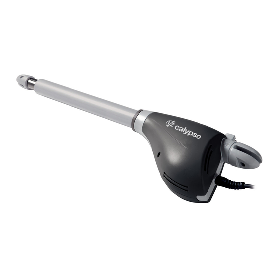
CALYPSO
www.remotecontrolgates.co.uk
IL n.186-A
EDIZ. 30/11/2006
Advertisement
Table of Contents

Summary of Contents for V2 Calypso400
- Page 1 V2 ELETTRONICA SPA Corso Principi di Piemonte, 65/67 - 12035 RACCONIGI (CN) ITALY tel. +39 01 72 81 24 11 fax +39 01 72 84 050 IL n.186-A info@remotecontrolgates.co.uk www.remotecontrolgates.co.uk EDIZ. 30/11/2006 CALYPSO ATTUATORE ELETTROMECCANICO IRREVERSIBILE PER CANCELLI A BATTENTE...
-
Page 2: Technical Data
TECHNICAL DATA Calypso Calypso Calypso400 Calypso500 400-120V 500-120V Max. leaf lenght Max. leaf weight Power supply VAC - Hz 230 - 50 230 - 50 120 - 60 120 - 60 Idling current Full load current Maximum Power Capacitor µF... -
Page 3: Installation Layout
INSTALLATION LAYOUT cable 4 x 1 mm (RX) cable 4 x 1 mm CALYPSO actuator Internal photocells cable 2 x 1 mm (TX) cable 2 x 1,5 mm Blinker cable 4 x 1 mm (RX) cable RG-58 Aerial External photocells cable 2 x 1 mm (TX) cable 2 x 1 mm... - Page 4 INSTALLATION MEASURES CALYPSO 500 To carry out a proper installation of the operator parts as well γ γ as to ensure the best automation performance, the A [mm] B [mm] C [mm] F [mm] measurement levels shown in the following table shall be 1200 complied with.
- Page 5 • The brackets must be installed at the same height. • The maximum stroke of arm A should not exceed 456 mm for CALYPSO400 and 556 mm for CALYPSO500 (in case of gate completely closed). • The minimum stroke of arm B must be more than 56 mm (in...
-
Page 6: Emergency Release
TO CONNECT CALYPSO WITH CONTROL UNIT YELLOW - GREEN BLUE (230V mod.) COMMON WHITE (120V mod.) WARNING: always remember to connect the earth according to current standards (EN 60335-1, EN 60204-1). BLACK CLOSING BROWN OPENING EMERGENCY RELEASE In case of a blackout, the gate can be operated directly from the motor. - Page 7 V2 S.p.A. Corso Principi di Piemonte, 65/67 - 12035 RACCONIGI (CN) ITALY tel. +39 01 72 81 24 11 fax +39 01 72 84 050 IL n. 252-1 info@v2home.com www.v2home.com EDIZ. 12/11/2007 City7 (Pr. 1.0) CENTRALE DI COMANDO ANALOGICA PER...
- Page 8 ELECTRICAL CONNECTION TABLE PLEASE NOTE: If not used, the normally closed inputs (STOP, PHOTO, EDGE) must be jumpered with the commands common line COM (-) Antenna K1 - K2 Courtesy light timer activation switch Antenna shield Motor 1 open Opening command for a standard connection device Motor 1 common with switch normally open.
-
Page 9: Installation
INSTALLATION PHOTOCELLS Installation of the control unit, the safety devices and accessories The control unit has a 24VAC power supply for photocells with must be performed with the power supply disconnected. switch normally closed, and can perform an operational test before to starting the gate opening procedure. -
Page 10: Start Input
Conductive rubber edge: connect the edge cables between STOP terminals L7 and L8 on the control unit. The STOP input is intended for devices with the switch normally closed. The STOP command causes the immediate stop of the gate. A subsequent START command activates the gate in the opposite direction of movement. - Page 11 PROGRAMMING THE OPERATIONAL LOGIC It is possible for the control unit to use several different operational logic states, by simply moving the dip-switches located on the card. The functions associated with each individual dip-switch are listed below. FUNCTION SETTING DESCRIPTION Disabled The blinker is switched on when the motors are started Pre-flashing...


Need help?
Do you have a question about the Calypso400 and is the answer not in the manual?
Questions and answers