Table of Contents
Advertisement
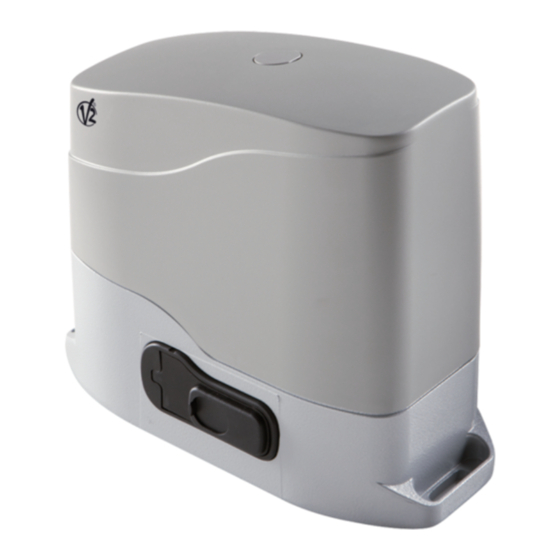
Gold400D / Gold600D
ATTUATORE ELETTROMECCANICO 230V / 120V IRREVERSIBILE A
I
CREMAGLIERA PER CANCELLI SCORREVOLI FINO A 600 /400 KG
DI PESO. CENTRALE DI COMANDO DIGITALE INCORPORATA
230V / 120V ELECTRO-MECHANICAL IRREVERSIBLE RACK
GB
ACTUATOR FOR SLIDING GATES UP TO 600 /400 KG.
BUILT-IN DIGITAL CONTROL UNIT
OPERATEUR ELECTROMECANIQUE 230V / 120V IRREVERSIBLE
F
A CREMAILLERE POUR PORTAILS COULISSANTS JUSQU'A
600 /400 KG DE POIDS. ARMOIRE DE COMMANDE NUMÉRIQUE
INCORPORÉE
MOTORREDUCTOR ELECTROMECÁNICO 230V / 120V
E
IRREVERSIBLE A CREMALLERA PARA PUERTAS CORREDERAS
HASTA 600 /400KG DE PESO. CUADRO DE MANIOBRAS DIGITAL
INCORPORADO
V2 S.p.A.
Corso Principi di Piemonte, 65/67
12035 RACCONIGI (CN) ITALY
tel. +39 01 72 81 24 11 - fax +39 01 72 84 050
info@v2home.com - www.v2home.com
IL n. 267-1
EDIZ. 28/09/2009
Advertisement
Table of Contents

Subscribe to Our Youtube Channel
Related Manuals for V2 Gold Series


Summary of Contents for V2 Gold Series
- Page 1 V2 S.p.A. Corso Principi di Piemonte, 65/67 12035 RACCONIGI (CN) ITALY IL n. 267-1 tel. +39 01 72 81 24 11 - fax +39 01 72 84 050 EDIZ. 28/09/2009 info@v2home.com - www.v2home.com Gold400D / Gold600D ATTUATORE ELETTROMECCANICO 230V / 120V IRREVERSIBILE A CREMAGLIERA PER CANCELLI SCORREVOLI FINO A 600 /400 KG DI PESO.
-
Page 2: Table Of Contents
INDEX IMPORTANT REMARKS ............... . .26 CONFORMITY TO REGULATIONS . -
Page 3: Important Remarks
IMPORTANT REMARKS CONFORMITY TO REGULATIONS V2 S.p.A. declares that the series of GOLD actuators are in For any installation problems please contact V2 S.p.A. TEL. (+39) 01 72 81 24 11 conformity with the provisions of the following EC directives: V2 S.p.A. -
Page 4: Parts List
TECHNICAL GOLD600D-230V GOLD600D-120V GOLD400D-230V GOLD400D-120V SPECIFICATIONS GOLD600DM-230V GOLD600DM-120V GOLD400DM-230V GOLD400DM-120V Gate maximum weight 600 Kg 600 Kg 400 Kg 400 Kg Power supply 230V / 50Hz 120V / 60Hz 230V / 50Hz 120V / 60Hz Maximum power 500 W 500 W 350 W 400 W Idling current... -
Page 5: Preparatory Steps
PREPARATORY STEPS WARNING: insert the gasket in the hole through CAREFULLY OBSERVE EUROPEAN REGULATIONS EN12445 AND which the cables pass, as shown in the picture. Pierce the EN12453 (WHICH REPLACE UNI 8612). gasket in order to let pass the cables to be connected to the central unit, being careful of narrowing them in order Always check the following: to avoid the entrance of bugs and small animals. -
Page 6: Installing The Limit Switches
INSTALLING THE MAGNETIC LIMIT SWITCHES Install the supplied magnet holder on the rack in a way that, in the opening and closing limit positions, the magnet be positioned next to the magnetic sensor behind the hood (as near as possible to the hood). The supplied magnets have been colored differently in order to be distinguished from each other: RED MAGNET CLOSING LIMIT SWITCH... -
Page 7: Motor Overriding System
MOTOR OVERRIDING SYSTEM WARNING: In case the leaf overruns its final position In case of a blackout, the gate can be operated directly from the and impacts against the safety stroke end (i.e. wrong motor. Insert the key supplied in the lock 1 on the front side of regulation of the limit switches),and a manual unclamp the motor, perform 1/4 of a turn and open the plastic door would be necessary, before using the above procedure,... -
Page 8: Description Of The Control Unit
Pd8-120V) blinker equipped with intermittence inside. Connect blinker cables to terminals 13 and 14 of the control The digital control unit Pd8 is an innovative V2 S.p.A. product unit. that guarantees a safe and reliable automation of sliding gates. -
Page 9: Safety Ribbons
SAFETY RIBBONS END OF STROKE Limit sensors come connected already to terminals 22, 23, 24 The control unit makes it possible to use standard edges with and 25 by means of a polarized connector. normally closed contacts or wireless edges (see the instructions provided with the device). -
Page 10: Plug In Receiver
• Timer mode: it is similar to the standard mode but the gate EXTERNAL AERIAL stays open (completely or partially) while the contact is closed We suggest to use the external aerial (model: ANSGP433) in on input; as soon as the contact is open the pause time count order to guarantee the maximal range. -
Page 11: Use Of Down Menu And Up Keys For Programming
USE OF DOWN MENU AND UP KEYS FOR Time menu setup Time menus allow setting a function duration. When you enter PROGRAMMING into a time menu, the current setup value will be viewed; the Control unit time and function programming is made within a display mode depends on the current value: special configuration menu, to which you can access and where you can shift through DOWN, MENU and UP keys placed on the... -
Page 12: Quick Configuration
QUICK CONFIGURATION This paragraph concerns a quick procedure to set the control unit and set it at work immediately. We recommend following these instructions, in order to check quickly the correct operation of control unit, motor and accessories, and then changing the configuration in case of any non-satisfactory parameter. - Page 13 LOADING OF DEFAULT PARAMETERS 3. While displayed the revision of the firmware, press the key UP: the control unit displays a countdown (from dE.-9 to If necessary, it is possible to restore all the parameters to their dE-1). standard or default value (see table at the end) 4.
- Page 14 Pre-blinking time Before any gate movement, blinker will be activated for t.PrE time, to warn about the incoming motion. Gate Direction This menu allows to invert the opening direction of the gate without swapping motor wires and limit switch ones. the gate opens rightwards the gate opens leftwards WARNING: “opening direction of gate”...
- Page 15 Slowing down time In case this function is enabled, during the last seconds of motion, the control unit will give motor a reduced power command, to avoid a strong impact with the stop end. t.AP is the max. allowed time. WARNING: •...
- Page 16 Pedestrian Start during the partial opening phase This menu allows fixing the control unit conduct in case it receives a Pedestrian Start command during the partial opening phase. PAUS The gate stops and goes to pause ChiU the gate immediately starts closing the gate goes on with the opening phase (command is ignored) WARNING: a Start command in any phase of partial opening will cause the total opening;...
- Page 17 Start input function This menu allows selecting input operation modes (see paragraph “Activation inputs”): StAn Start and Pedestrian Start input standard operation, according to menu setups. Start inputs from terminal board are disabled. Radio inputs operate in StAn mode. AP.CH Start impulse always controls the opening phase, Pedestrian Start always controls the closing phase.
- Page 18 Photocell 1 input This menu allows enabling the input for type 1 photocells, that is to say, photocells active both during the opening and closing phase (see paragraph “Installation”). input disabled (ignored by the control unit). No jumper with the common is required. AP.CH input enabled.
- Page 19 No jumper with the common is required. input enabled. Enabling WIRELESS edges This menu makes it possible to enable the edge input to operate with V2 WIRELESS edges Input disabled Input enabled End of Stroke Inputs Pd8 control unit allows connecting magnetic limit switch which are activated by the door motion and showing to the control unit that each door reached its position of complete opening or closing.
- Page 20 Counter viewing This menu allows viewing the counter of completed opening cycles and it also enables the final user to set up the times of service required (see paragraph “Reading of cycle counter” below). Automatic Learning of the Operation Time This menu will activate a procedure enabling the control unit to automatically find the best duration of the operation time.
-
Page 21: Reading Of Cycle Counter
READING OF CYCLE COUNTER Pd8 control unit counts the completed opening cycles of the gate and, if requested, it shows that service is required after a fixed number of cycles. There are two counters available: • A totalizing counter for completed opening cycles that cannot be zeroed (option “tot”... -
Page 22: Obstacle Sensor Operation
This paragraph shows some possible operation defects, along Change the end of stroke sensor or the broken wiring. with their cause and applicable remedy. If the error persists send the control unit to V2 S.p.A. for repair. MAINS led does not switch on Error 5 It means that there is no voltage on Pd8 control unit card. -
Page 23: Pd8 Function Table
Pd8 FUNCTION TABLE MEMO DISPLAY DATA DESCRIPTION DEFAULT DATA t.AP 0.0" ÷ 2.0' 15.0" Gate opening time t.APP 0.0" ÷ t.AP1 6.0" Opening time of pedestrian gate t.Ch 0.0" ÷ 2.0' 16.0" Gate closing time t.ChP 0.0" ÷ t.Ch 7.0" Closing time of pedestrian gate t.PrE 0.5"... - Page 24 Pd8 FUNCTION TABLE MEMO DISPLAY DATA DESCRIPTION DEFAULT DATA St.rt StAn Operation modes StAn - Start inputs from terminal board are disabled - Standard operation AP.CH - Separated opening and closing commands PrES - Manned operation oroL - Timer operation FrEn 0 ÷...
-
Page 25: Electric Connections Table
ELECTRIC CONNECTIONS TABLE Neutral 230 VAC / 120VAC Opening control for the connection of control devices with N.O. contact Power phase 230 VAC / 120VAC Opening controls for pedestrian access for the Antenna connection of control devices with N.O. contact Antenna shield Stop command.
Need help?
Do you have a question about the Gold Series and is the answer not in the manual?
Questions and answers