Table of Contents
Advertisement
Available languages
Available languages
Quick Links
8XT
8XT
8XT
8XT
coaxial enclosure
coaxial enclosure
coaxial enclosure
coaxial enclosure
i
8XT
8XT
8XT
8XT
enceinte coaxiale
enceinte
enceinte
enceinte
i
VERSION 1.0
VERSION 1.0
VERSION 1.0
VERSION 1.0
coaxiale
coaxiale
coaxiale
w w w . l - a c o u s t i c s . c o m
USER MANUAL
MANUEL D'UTILISATION
EN
FR
Advertisement
Chapters
Table of Contents

Related Manuals for L-Acoustics 8XTi


Summary of Contents for L-Acoustics 8XTi
- Page 1 coaxial enclosure coaxial enclosure coaxial enclosure coaxial enclosure enceinte enceinte coaxiale coaxiale enceinte enceinte coaxiale coaxiale VERSION 1.0 VERSION 1.0 VERSION 1.0 VERSION 1.0 USER MANUAL MANUEL D’UTILISATION w w w . l - a c o u s t i c s . c o m...
- Page 2 w w w . l - a c o u s t i c s . c o m...
-
Page 3: Safety Warnings
2. Heed all safety warnings 3. Follow all instructions ® 4. The user should never incorporate equipment or accessories not approved by L-ACOUSTICS Sound Levels Sound systems are capable of producing high Sound Pressure Levels which can be dangerous and potentially cause hearing damage especially when exposed to them over a long period of time. - Page 4 8 8 8 8 XT COAXIAL ENCLOSURE COAXIAL ENCLOSURE COAXIAL ENCLOSURE COAXIAL ENCLOSURE user manual user manual user manual user manual VERSION 1.0 Water and moisture Even if the product is weather-resistant, it can not be exposed to moisture (rain, sea spray, shower, steam) for a long period of time, nor put in direct contact or partially immersed in water.
-
Page 5: Ec Declaration Of Conformity
13 rue Levacher Cintrat Parc de la Fontaine de Jouvence 91462 Marcoussis Cedex France States that the following product: Loudspeaker enclosure, 8XTi Is in conformity with the provisions of: Machinery Directive 2006/42/EC Low Voltage Directive 2006/95/EC Applied rules and standards:... -
Page 6: Table Of Contents
Connecting the 8XTi to the LA4.......................12 7.3.3 [8XT_FR_100], [8XT_FI_100], and [8XT_MO_100] presets.............13 “HYBRID’’ mode .............................13 7.4.1 Description............................13 7.4.2 Connecting the 8XTi and SB118 to the LA4..................13 7.4.3 [8XT_SB118] preset.........................14 CARE AND MAINTENANCE Maintenance information ..........................15 Testing procedure ............................15 8.2.1 Check of transducer and enclosure acoustic behavior................15 8.2.2... -
Page 7: Introduction
Unpacking ® Carefully open the shipping carton and check the product for any noticeable damage. Each L-ACOUSTICS product is tested and inspected before leaving the factory and should arrive in perfect condition. If found to be damaged, notify the shipping company or the distributor immediately. Only the consignee may initiate a claim with the carrier for damage incurred during shipping. - Page 8 SP.7, SP10, and SP25 loudspeaker cables with respective lengths of 0.7 m/2 ft, 10 m/30 ft, and 25 m/80 ft. These cables allow connection of the 8XTi and 12XTi enclosures to the LA4 amplified controller. Each cable is a 4-conductor cable with 4 mm conductor cross-section (13 SWG, 11 AWG) and features ®...
- Page 9 8XTi 12XTi ETR8XTi ETR12XTi EMBi SB118 SOUNDVISION LA NETWORK MANAGER SP25 SP.7 SP10 Figure 1: XTi series components w w w . l - a c o u s t i c s . c o m 8XTI_UM_ML_1-0 7 7 7 7 en...
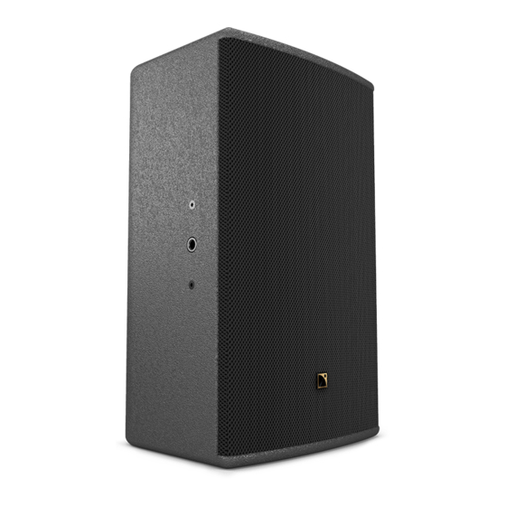
- Page 10 The wedge-shaped cabinet design makes the 8XTi perfectly suited to all stacked sound reinforcement applications. The cabinet can also be pole, wall, or ceiling-mounted. The 8XTi cabinet is made of high grade Baltic birch plywood with remarkable mechanical and acoustical properties for improved long term durability.
-
Page 11: Installation
The 8XTi enclosure is driven and powered by the dedicated L-ACOUSTICS LA4 amplified controller. Each LA4 amp channel can drive one or two (in parallel) 8XTi enclosures. For more details, please, refer to the “LA4’’ user manual ® also available on the L-ACOUSTICS web site at www.l-acoustics.com. - Page 12 Length for two 8XTi (4 load) According to the calculation in Table 1, one SP25 cable (4 mm², 25 m) can be used to power two 8XTi in parallel (4 load) with a damping factor still greater than 20. w w w . l - a c o u s t i c s . c o m...
-
Page 13: Operation
Each 8XTi enclosure must be connected to an LA4 output channel ranging from channel 1 through 4. An additional 8XTi enclosure can be connected in parallel with each of the first ones. Therefore, a single LA4 amplified controller can drive up to eight 8XTi enclosures (see Figure 4). -
Page 14: 8Xt_Fr], [8Xt_Fi], And [8Xt_Mo] Presets
Each 8XTi enclosure must be connected to an LA4 output channel ranging from channel 1 through 4. An additional 8XTi enclosure can be connected in parallel with each of the first ones. Therefore a single LA4 amplified controller can drive up to eight 8XTi enclosures (see Figure 5). -
Page 15: 8Xt_Fr_100], [8Xt_Fi_100], And [8Xt_Mo_100] Presets
Connecting the 8XTi and SB118 to the LA4 The 8XTi and SB118 enclosures connect to the LA4 outputs as follows: channels 1 and 3 are dedicated to one SB118 enclosure each, and channels 2 and 4 to 8XTi enclosures. Each 8XTi enclosure can be paired in parallel with an additional 8XTi. -
Page 16: 8Xt_Sb118] Preset
OUT 4 (IN B) OUT 3 (IN B) OUT 2 (IN A) Figure 6: Four 8XTi and two SB118 enclosures connected to an LA4 controller 7.4.3 [8XT_SB118] preset The [8XT_SB118] preset features a HF shelving EQ for FOH applications. The crossover frequency between the LF and HF sections is set at 100 Hz. -
Page 17: Care And Maintenance
Oxidation-resistant screws and rigging points. However, in order to ensure product performance and safety, it is essential to frequently inspect the 8XTi cabinet and its internal components. These checks need to be done on a regular basis depending on the conditions of system use. -
Page 18: Transducer Service
LF loudspeaker If damaged, the 8” LF loudspeaker should be removed and repaired or replaced as described below. Recone kits are ® available. Alternatively, reconing can be performed by L-ACOUSTICS (see section 8.4). LF loudspeaker removing procedure 1. Put the enclosure on a flat surface with grill facing the user. -
Page 19: Spare Parts And Recommended Tools
HF driver or diaphragm replacing procedure To install a full HF driver: Install the new driver on the heat dissipation plate (if necessary, add a few additional thermal paste above the old thermal paste on the driver in a continuous circular way). ®... -
Page 20: Specifications
External structure Material 15 mm Baltic birch plywood. ® ® Standard finish Grey Brown RAL 8019 (8XTi) or Pure White RAL 9010 (8XTiW). Custom finish RAL code on special order. Front Polyester powder-coated steel grill, acoustically transparent “Airnet” fabric. Rigging Polyester powder-coated steel. - Page 21 Suivre les consignes de sécurité Suivre les instructions ® N’utiliser en aucun cas des équipements ou accessoires non approuvés par L-ACOUSTICS Niveaux sonores Les systèmes de sonorisation sont capables de délivrer un niveau sonore SPL nuisible à la santé humaine. Les niveaux sonores apparemment non critiques peuvent endommager l’audition si la personne y est exposée pendant une longue période.
- Page 22 8 8 8 8 XT ENCEINTE COAXIALE ENCEINTE COAXIALE ENCEINTE COAXIALE ENCEINTE COAXIALE m m m m anuel d’utilisation anuel d’utilisation anuel d’utilisation anuel d’utilisation VERSION 1.0 Eau et humidité Bien que peu sensible à l’humidité, le produit ne peut être exposé de manière durable à des projections d’eau (pluie, embruns, douches, vaporisation) ni être au contact de l’eau ou partiellement immergé, sous peine de détérioration irréversible de certains des composants exposés.
- Page 23 13 rue Levacher Cintrat Parc de la Fontaine de Jouvence 91462 Marcoussis Cedex France Déclare que le produit suivant : Enceinte acoustique, 8XTi Est conforme aux dispositions de : Directive Machine 2006/42/CE Directive Basse Tension 2006/95/CE Règles et standards appliqués : EN ISO 12100-1 : 2004 (Sécurité...
- Page 24 Raccordement de l’enceinte 8XTi au LA4 ..................12 7.3.3 Les presets [8XT_FR_100], [8XT_FI_100], et [8XT_MO_100]............13 Le mode “HYBRIDE” ............................13 7.4.1 Description............................13 7.4.2 Raccordement des enceintes 8XTi et SB118 au LA4................13 7.4.3 Le preset [8XT_SB118] ........................14 ENTRETIEN ET MAINTENANCE Informations pour la maintenance ........................15 Procédure de vérification..........................15 8.2.1 Vérification des transducteurs et du comportement acoustique de l’enceinte ........15...
-
Page 25: Introduction
Si le produit nécessite une réparation ou pour tout renseignement sur la garantie, contacter un distributeur agréé. ® Les coordonnées du distributeur le plus proche sont disponibles sur le site internet L-ACOUSTICS Déballage du produit Dès réception, inspecter soigneusement le produit afin de détecter un éventuel défaut. Chaque produit ®... - Page 26 L-ACOUSTICS SP.7, SP10, et SP25 de longueurs respectives 0,7 m/2 ft, 10 m/30 ft, et 25 m/80 ft pour connecter les enceintes 8XTi et 12XTi au contrôleur amplifié LA4. Chaque câble ® comporte 4 conducteurs de section 4 mm (13 SWG, 11 AWG) et est muni de connecteurs Speakon 4 points.
- Page 27 8XTi 12XTi ETR8XTi ETR12XTi EMBi SB118 SOUNDVISION LA NETWORK MANAGER SP25 SP.7 SP10 Figure 1 : Éléments de la série XTi w w w . l - a c o u s t i c s . c o m...
- Page 28 L’ébénisterie à pans coupés est étudiée pour une utilisation polyvalente en posage. L’enceinte peut également être montée sur pied ou accrochée à un mur ou un plafond. L’enceinte 8XTi est réalisée en multipli de bouleau balte de premier choix aux propriétés mécaniques et acoustiques remarquables pour une durabilité éprouvée.
-
Page 29: Installation
L’enceinte 8XTi est pilotée et amplifiée par le contrôleur amplifié dédié L-ACOUSTICS LA4. Chaque canal d’amplification du LA4 peut alimenter une ou deux (en parallèle) enceintes 8XTi. Pour plus de détail, merci de consulter le manuel d’utilisation ‘‘LA4’’ téléchargeable du site internet www.l-acoustics.com. - Page 30 Longueur pour une 8XTi (8 ) Longueur pour deux 8XTi (4 ) Selon le Tableau 1, un câble SP25 (4 mm², 25 m) peut alimenter 2 enceintes 8XTi en parallèle (impédance 4 ) avec un facteur d’amortissement supérieur à 20.
-
Page 31: Exploitation
Le mode “LARGE BANDE” 7.2.1 Description Dans le mode “LARGE BANDE” les enceintes 8XTi sont utilisées seules sur leur bande passante nominale (65 Hz – 20 kHz) pour des applications ne nécessitant pas de renfort sub-grave. 7.2.2 Raccordement de l’enceinte 8XTi au LA4 Chaque enceinte 8XTi est raccordée à... -
Page 32: Les Presets [8Xt_Fr], [8Xt_Fi], Et [8Xt_Mo]
7.3.2 Raccordement de l’enceinte 8XTi au LA4 Chaque enceinte 8XTi est raccordée à une sortie du contrôleur amplifié LA4, successivement de 1 à 4 pour les quatre premières. Une enceinte 8XTi supplémentaire peut être connectée en parallèle avec chaque première. Un seul contrôleur amplifié... -
Page 33: Les Presets [8Xt_Fr_100], [8Xt_Fi_100], Et [8Xt_Mo_100]
Les enceintes 8XTi et SB118 sont raccordées aux canaux d’amplification du LA4 de la manière suivante : les canaux 1 et 3 sont dédiés chacun à 1 enceinte SB118, les canaux 2 et 4 aux enceintes 8XTi. Il est possible d’associer une seconde enceinte 8XTi en parallèle avec chaque première. -
Page 34: Le Preset [8Xt_Sb118]
OUT 2 (IN A) Note : Cette figure représente un schéma de câblage et non une configuration d’installation. Figure 6 : Quatre 8XTi et deux SB118 connectées à un contrôleur amplifié LA4 7.4.3 Le preset [8XT_SB118] Le preset [8XT_SB118] inclut un shelving HF adapté aux applications de façade. Le raccordement entre les sections LF et HF se situe à... -
Page 35: Informations Pour La Maintenance
Toutefois, pour assurer les performances et la sécurité du produit, il est indispensable de vérifier fréquemment l’état de l’enceinte 8XTi et de ses organes internes. La fréquence de ces vérifications dépend des conditions d’utilisation du système. La procédure de vérification comprend essentiellement trois étapes décrites en section 8.2. Si un transducteur doit être réparé... -
Page 36: Maintenance Des Transducteurs
Haut-parleur LF En cas de détérioration, le haut-parleur LF 8’’ doit être démonté et réparé ou remplacé selon la procédure suivante. ® Des kits de remembranage sont disponibles. Le montage peut aussi être effectué par L-ACOUSTICS (voir la section 8.4). -
Page 37: Pièces Détachées Et Outils Recommandés
Remplacement du moteur HF ou du diaphragme 1. Pour installer un moteur HF entier : a. Installer le nouveau moteur sur la plaque de dissipation thermique (si nécessaire, ajouter un peu de pâte thermique sur l’ancienne encore présente sur le moteur dans un mouvement circulaire continu). ®... -
Page 38: Spécifications Techniques
® OMNIMOUNT SÉRIE 30.0. Insert de sécurité. Posage Angles à 30° et 40° par rapport à la verticale. ® Embase pied ajustable 35 mm/1.4 inch L-ACOUSTICS EMBi (disponible séparément). Structure externe Matériau Multipli de bouleau balte 15 mm. ® ®... - Page 39 w w w . l - a c o u s t i c s . c o m...
- Page 40 Document reference: 8XTi_UM_ML_1-0 _________________ ® © 2009 L-ACOUSTICS . All rights reserved. No part of this publication may be reproduced or transmitted in any form or by any means without the express written consent of the publisher. _________________ Distribution date: January 7 , 2010 w w w .
Need help?
Do you have a question about the 8XTi and is the answer not in the manual?
Questions and answers