Table of Contents
Advertisement
..........................................................................................
...................................................................................................
3-1 Specifications & Features............................................................................
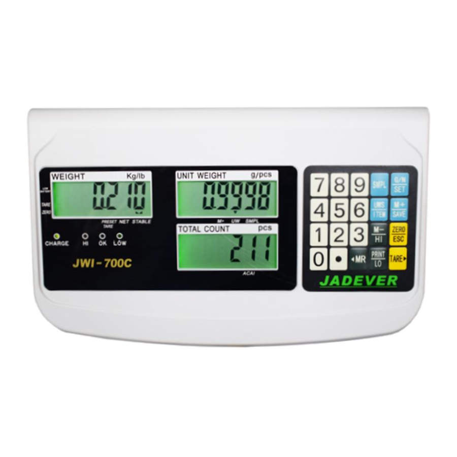
3-2-1 Display ................................................................................................
3-2-2 Keyboard..............................................................................................
3-3 Rear Panel..............................................................................................
3-4 Power Supply...........................................................................................
4-1 Load Cell Connection.................................................................................
4-2 Assembly Description of Upright Pole............................................................
5-1 Maximum Weighing Capacity Setting............................................................
5-2 Resolution Setting.....................................................................................
5-3 Function Setting ......................................................................................
6-1 Linear calibration......................................................................................
6-2 Single point calibration...............................................................................
7-1-1 Weighing..............................................................................................
7-1-3 Unit Switch Operation ............................................................................
7-2-1 Upper & Lower Quantity Limit Checking ......................................................
7-2-2 Entering a Known Unit Weight ..................................................................
7-2-3 Sample Counting & ACAI.............................................................................
7-2-4 Accumulation, Accumulation Display and Accumulation Clear..........................
8-1 RS-232 Connector.....................................................................................
8-2 Single Option...........................................................................................
8-3 RS-232 Output Format...............................................................................
Table of Contents
...................................................
JWI-700C
1
1
1
2
3
4
5
5
5
7
7
8
10
10
11
11
12
12
12
13
13
14
15
15
16
0
Advertisement
Table of Contents

Related Manuals for Jadever JWI 700C


Summary of Contents for Jadever JWI 700C
-
Page 1: Table Of Contents
Table of Contents 1. Introduction ……………………………………………………………………………… 2. Precaution ……………………………………………………........3. Product Introduction 3-1 Specifications & Features………………………………………………………………..3-2 Front Panel 3-2-1 Display …………………………………………………………………………………… 3-2-2 Keyboard…………………………………………………………………………………. 3-3 Rear Panel…………………………………………………………………………………. 3-4 Power Supply………………………………………………………………………………. 4. Installation 4-1 Load Cell Connection……………………………………………………………………… 4-2 Assembly Description of Upright Pole…………………………………………………… 5. -
Page 2: Introduction
1. Introduction Thank you for deciding to purchase a JWI-700C Counting indicator from Jadever. This goods has the excellent performance and splendid properties under severe quality management .It is recommended to read this manual in full before using it for good function application. -
Page 3: Front Panel 3-2-1 Display
Features ‧LCD display 6/5/6, LED backlight ‧Kg and Lb switchable ‧Up to 1/30000 resolution ‧ Adjustable capacities, resolutions and parameters ‧Adjustable stand for bench scale ‧Enclosed with PVC dustproof cover ‧Able to adjust filter range and zero band ‧Low battery and charging status indicator ‧Automatic average weighing unit function ‧Single point and linear calibration available ‧HI/OK/LO indicator, HI/OK/LO alarm function... -
Page 4: Keyboard
Center of Zero Indication, The zeroing range is ±2﹪of weighing capacity. 4) Charge Lamp 5) HI Lamp (ON) –Indicating parameter item is selected when setting buzz sounds. (See 5. Function Setting, setting buzz sounds) OK Lamp (ON) -- Indicating parameter item is selected when setting buzz sounds. -
Page 5: Rear Panel
2) ● key Decimal point ; toggles between upper limit and lower limit setting when HI-LO-OK function is enabled .(see 7-2-1) PRINT key Outputs data when Prt.Pr (print stably) is selected as the print mode. ZERO key Zeros the display (within 2% of max.capacity) or cancels Tare action. TARE key Inputs the weight of the object on the weighing pan as a Tare value ;... -
Page 6: Power Supply
3-4 Power supply Please verify the local AC power source and switch the two-stage switch to the proper place before plugging into the power outlet. Alternative power supply 1) AC 110V/220V (AC±10%) 2) (6V/4A) Internal Rechargeable Battery Power Consumption About 300mW, 80hrs (without backlight) About 380 mW, 65hrs (with backlight) Low battery warning When “... - Page 7 Step 1: Thread the wire of the Load Cell (9)on the rod seat (1) through the upright pole (2), insert the upright pole into the rod seat and then lock it with two screws (5). Step 2: After threading the Load Cell wire through the bracket (3), attach the bracket to the upright pole and then lock it with the screw (6).
-
Page 8: Setting Mode
5. Setting Mode 5-1 Maximum Weighing Capacity Setting ZERO 1) Turn on the power while pressing key 2) Press key ● to cycle through weight capacity options. Available settings are 15,30,60,75,150,300,600, 750,1500,3000,6000 and7500 (kg).Here we choose (75kg). SMPL 3)Press key to save and return to the Setting Menu. -
Page 9: Function Setting
5-3 Function Setting ZERO 1) Turn on the power while pressing key Note: The following Steps (2) ~ (11) do not require to operate in order. 2) Press numeric key to shift backlight modes. Options are On, OFF and OnOFF. =Auto-on with items greater than 9d placed on the pan. -
Page 10: Calibration Mode
= There will be a warning sound when the material quantity is less than the lower limit, and the weight of the material is more than 20 divisions. = No sound alarm. 8) Press numeric key to set whether to save the upper &... -
Page 11: Linear Calibration
6-1 Linear calibration TARE 1)Turn on the power while pressing key to initiate linear calibration. TARE 2) Again press key to enter zero calibration mode, with “ ”flashing on the weight window. 3) Wait till “ ” appears put weights of 1/3 of full load on the weighing pan and press down key TARE . -
Page 12: Operation
4) Wait till “” ”is stable, key in the calibration value 25(1/3 full load) and put the corresponding weights On, then press key . “25” is flashing. 5) The calibration procedure is completed with a“ ” flashing on the weight screen. Now, remove all the weights. SMPL ZERO 6) Press key... -
Page 13: Unit Switch Operation
7-1-3 Unit Switch Operation SMPL 1) Press key while powering on the scale. 2) Key in 1132 via numeric keys. SMPL 3) Again press key to enter unit selection mode. Numeric key is to toggle between kg and Lb units. SMPL ZERO 4) Press key... -
Page 14: Sample Counting & Acai
Note: Symbol “ ” points at “UW” when entered unit weight is lower than 4/5 of scale division. 7-2-3 Sample Counting & ACAI Sample Counting 1) Place samples onto the weighing pan (Or into a tared container) and input the SMPL quantity with numeric keys, then press key Symbol “... -
Page 15: Serial Interface
3) Put the second piece of load on, then press key to add the second accumulation event into memory. Repeat step 2-3 till accumulation actions are finished. Note: Maximum is 99 pieces. Accumulation display Press key to displays the total accumulation data (weight, count and number of weighments) and the first 10 accumulation events in detail. -
Page 16: Single Option
8-2 Single Option 1) RS232+RTC+Relay+ TDP / SH-24(TP)/ ZEBRA / GODEX printer 2) RS232+RTC+Relay+ LED Light Tower (Applicable to the quality control of the factory product quantity or weight and that of the total production line.) 3) RS232+RTC+Relay+Computer 8-4 RS-232 Output Format Baud Rate :... -
Page 17: Troubleshooting And Error Message
9. Troubleshooting and Error message Error message Problems Solutions Initial zero point exceeds + 1. To check whether there are other alien /-30% (take articles on the scale pan, remove those reference basis). articles. 2. LOAD CELL failure, which requires to be changed or to contact our Service. - Page 18 JWI-700C...
- Page 19 JWI-700C...
- Page 20 JWI-700C...
Need help?
Do you have a question about the JWI 700C and is the answer not in the manual?
Questions and answers
Err 2 check lond seal it ok