Table of Contents
Advertisement
Quick Links
Advertisement
Table of Contents

Related Manuals for Cannondale CONTRO-E CM2491SM01


Summary of Contents for Cannondale CONTRO-E CM2491SM01
- Page 1 1 3 3 0 8 2 C O N T R O - E L E M E N T A N U A L S U P P O W N E R ’ S M...
- Page 2 Cannondale Supplements Contents This manual is a “supplement” to your Cannondale Bicycle Owner’s Manual. This supplement provides additional and important model specific safety, maintenance, and technical information. It may be Safety InformatIon ............2-3 one of several important manuals/supplements for PartS of the e-SerIeS BIke ............4...
-
Page 3: Safety Information
25 km/h, (15.5 mph) as long as the pedals are turning. comply with local laws. Ask your Cannondale Dealer for more Whenever the drive assist system is turned OFF, You can pedal the bike information about operating an electrically assisted pedal normally. - Page 4 Follow brake manufacturer’s instructions when mounting the YOU IGNORE THESE WARNINGS. brake caliper to the spindle brake bosses. Do not modify the fork in any way. PLeaSe aSk your cannondaLe deaLer for heLP When InStaLLIng comPatIBLe front Brake SyStemS. NOTICE ■...
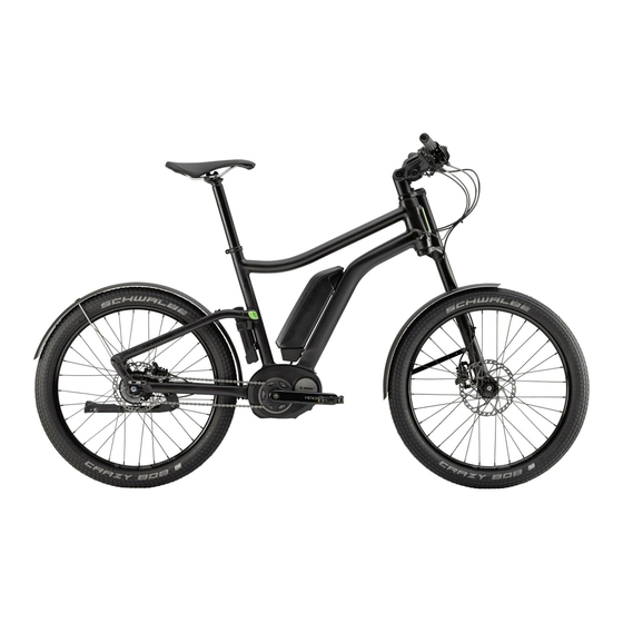
- Page 5 Parts of tHe e-serIes contro-e w/LEFTY rigid Drive Assist Display Battery Headlamp Kickstand Drive motor HEADSHOK fork 10 LEFTY Rigid Drive Control LEFTY Wheel Hub Rack Sensor/Spoke magnet Bell Folding Lock contro-e w/Headshok...
-
Page 6: Wheel Removal
Lefty rIGID Wheel Removal See Figure 1. Use a 5 mm Allen key to loosen the brake caliper mounting bolts enought to remove the brake caliper from the mounting tabs. Note brake alignment shims between brake bosses and the caliper. Replace correctly during reinstallation. See Figure 2. - Page 7 TO BE PERFORMED BY CANNONDALE DEALER : Recommended after the first 150 km, bring your bike to your Cannondale Dealer for an initial check-up. It should include checks of the drive assist system, drive chain condition, proper shifting, accessories, wheels and tire condition, brakes, etc. This visit will help you establish a schedule for repeated visits appropriate for how and where you ride.
-
Page 8: Tightening Torques
Never attempt to open, remove it from the frame, or work on it yourself. Other components of the eBike drive (e.g. drive chain, front chain ring, rear cassette, rear derailleur, crankarm) must be serviced by your Cannondale Dealer. Replacement parts must be identical to the original Cannondale specification for the bike. - Page 9 Geometry A - Seat Tube Length B - Top Tube Horizontal C - Head Tube Angle D - Seat Tube Angle E - Head Tube Length F - Wheelbase G - Front Center H - Chain Stay Length I - Bottom Bracket Drop J - Bottom Bracket Height K- Fork Rake L - Stack...
-
Page 10: Replacement Parts
rePLaCement Parts SI STEM KP358/ KA058/ KA058/ KA055/26 (FATTY) KA055/24 (LEFTY) DROPOUTS Fixed DROPOUT KITS FRAME/RACK/KICKSTAND KP356/ DROPOUT KIT (Fixed ) KA056/ KICKSTAND CDALE SI BLK 40mm Mount Plate DROPOUT KIT (Rear Derailleur) KP357/ KP358/ KIT RACK CONTRO BLK DROUPOUT KIT (fixed) contains A, B, C D KA058/ PLUGS, RACK ORTLIEB QL3 --For 26”... -
Page 11: Handlebar Adjustment
sI ConsoLe 6 Nm, 53InLbs 5 Nm, 44InLbs 15 Nm, 133InLbs 6 Nm, 53InLbs = Loctite 242 (blue) Handlebar Adjustment Head Lamp & Display Mounting The handlebar height is adjusted by loosening the pivot bolt (1) and The drive assist system display and head lamp and reflector brackets moving the arms (2) handlebar up or down to the desired position. - Page 12 n e r ’s m a n u a a le b ic y c le o w o u r c a n n o n d r e f e r e n c e . le m e n t a n d y t h f o r f u t u r e a d t h is s u p p t io n .
Need help?
Do you have a question about the CONTRO-E CM2491SM01 and is the answer not in the manual?
Questions and answers