Table of Contents
Advertisement
Advertisement
Table of Contents

Related Manuals for Simrad MO16-T


Summary of Contents for Simrad MO16-T
-
Page 1: User Manual
MO Series Monitors User Manual ENGLISH simrad-yachting.com... - Page 3 • Navionics is a registered trademark of Navionics SpA • Simrad is a trademark of Kongsberg Maritime AS Company registered in the US and other countries and is being used under license • B&G, StructureScan, Navico, SonicHub, SimNet, Skimmer, InsightHD, Broadband Radar...
- Page 4 About this manual This manual is a reference guide for installing and operating the Simrad MO Series monitors. The manual does not cover basic background information about how equipment such as radars, echosounders and AIS work. Important text that requires special attention from the reader is emphasized as follows: ¼...
-
Page 5: Table Of Contents
Contents Introduction Items included Display installation Cutout template Fixing options Flush-mounting the display VESA mounting the display Connecting the display Rear connections Cable retention Connecting power Connecting touch control Serial connection USB connection Connecting NMEA 2000 Connecting HDMI cable Typical installation Operating the display First time operation Shortcut functions... -
Page 6: Introduction
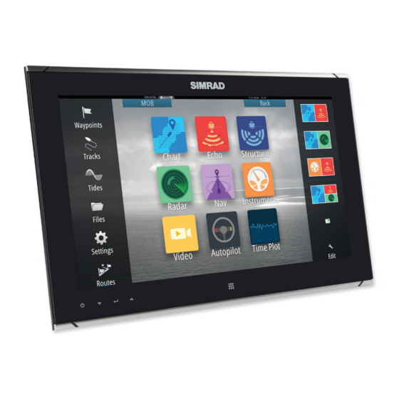
Introduction The Simrad MO Series monitors offer a low profile, high brightness solution for displaying video from a variety of sources. The range includes six models; the 16”, 19”, and 24” Touch series, and the 16”, 19” , and 24” Pilot series. The Touch models are suited to both indoor and outdoor (direct sunlight) use, whereas the Pilot series are suited to enclosed helm installations. -
Page 7: Display Installation
Display installation It is recommended that the unit be powered and connected to a video source to assist in selecting a suitable mounting location, prior to irreversable modification of the vessel’s helm station. When planning the display location, the following points should be considered to ensure safe, comfortable and reliable operation: •... -
Page 8: Flush-Mounting The Display
Flush-mounting the display ¼ Note: The following guidelines and warnings apply: Important drill bit size selection information 1.9 - 2.3 mm (5/64") Soft materials e.g. Plywood 2.3 - 2.5 mm (3/32") Hard materials e.g. GRP, Acrylic, hardwoods Max 5.5 mm (0.22”) Front mount screw recommendations Fit the supplied M4 machine screws,... - Page 9 Place the display in the dash hole. Place the guide tool on the glass of the display. Slide the tool across so the drill bit hole guide lines up with the center of a screw location hole on the case of the display. Drill the pilot hole.
- Page 10 With bracket making contact with back of monitor, slide bracket down till it engages with a click and is held in place. Wind in the wing screw, until stoppers make firm contact with rear of dashboard material. Check front of unit, ensuring that unit’s bezel is making even contact with the dash surface.
-
Page 11: Vesa Mounting The Display
VESA mounting the display A VESA bracket adaptor is available as an optional part for all display sizes, allowing a variety of wall and free standing bracket mounting options. The fasteners for attachment to the display are included with the bracket. Monitors mounted using a Vesa bracket have IPX2 rating, and should be mounted in an area sheltered from rain and sea spray. -
Page 12: Connecting The Display
Connecting the display The MO series monitors largely use industry standard cables, which can be purchased pre- terminated in a variety of lengths. The following chapter provides additional details of where cables require field termination by the installer. Rear connections Connection Function HDMI-1... -
Page 13: Connecting Power
The power input cable screen drain wire should be connected to a negative ground. ¼ Note: Chassis ground will typically not be required. In certain problematic installations it may help stabilize touch screen sensitivity, ie. prevent ‘false’ touches, or non-registered touches. Recommended fuse rating Model MO16-T MO19-T MO24-T MO16-P MO19-P MO24-P... -
Page 14: Connecting Touch Control
Connecting touch control The touch screen models of the MO series monitors can provide touch control to the NSO evo2 Marine Processor, as well as Windows 7 and Windows 8 PCs. Connection can be made via serial data for NOS evo2, or USB for PC systems. Serial connection The MO series monitors must always be connected to NSO evo2 via serial. -
Page 15: Connecting Nmea 2000
All hardware devices must be turned off prior to connecting or disconnecting the HDMI cable. Typical installation Description MO16-T/P, MO19-T/P, or MO24-T/P monitor HDMI cable (non HDCP sources only) DVI cable (eg. PC, non HDCP sources only) Composite video cable (eg. video camera) NSO evo2 Marine Processor FLIR®... -
Page 16: Operating The Display
Operating the display The display is configured and controlled using the row of touch sensitive buttons along the lower edge of the monitor frame. All buttons are backlit - only the power button is illuminated when the monitor is turned off. Power: long press turns display on/off. - Page 17 Option Sub option Setting Function Scaling HDMI-1 1:1, FILL, ASPECT Sets input image to true size, fill available screen area, or to fill screen DVI-2 vertically or horizontally but maintain VID-3 correct aspect ratio VID-4 Option Sub option Range Description Colour Temperature User, 6500K,...
-
Page 18: Updating The Firmware
OSD version, BIOS version, and the NMEA 2000 ID. Installing an Update Updates should be loaded via a compatible Simrad Multifunction Display or ST10 programming tool. Refer to the applicable product manual on how to upgrade a device over NMEA 2000. -
Page 19: Dimensional Drawings
Dimensional drawings MO16: 383mm MO19: 461mm MO24: 598mm MAX 25.4 mm (1.00") MO16: 400mm MO19: 478mm MO24: 625mm 8 mm (0.31") 66.0 mm (2.60") MAX 88.0 mm (3.46") | 19 Dimensional drawings | MO Series User Manual... -
Page 20: Troubleshooting Tips
Troubleshooting tips Issue Possible Cause No picture - red LED ON LED on continuously indicates no (compatible) video is available on currently selected source. Confirm that the correct video input is selected. Check that the video signal cable is properly connected to the display. -
Page 21: Cleaning And Maintenance
Cleaning and maintenance If the display requires cleaning, use a damp soft cloth (e.g. microfibre) with a mild, non- abrasive glass cleaner. Ensure cloth is regularly washed or replaced. ¼ Note: Do not use paper products as they may scratch the surface. To minimize the risk of abrasion, allow the screen to air dry. -
Page 22: Replacing The Filters
Replacing the filters Where displays are installed in an unsealed enclosure, air intake filters should be inspected yearly, and replaced if noticably fouled. If vessel is subject to major works involving spray painting or sanding, it is recommended that the monitor either be removed, or completely covered in a clean fabric drop cloth. -
Page 23: General Specifications
(8-32 bit colour, 25, 29, 30 Hz Interlaced) 1024 x 768 (8-32 bit colour, 60 Hz) ¼ Note: Occassionally specifications may change - refer to the latest edition of the manual on the website: www.simrad-yachting.com | 23 General specifications | MO Series User Manual... -
Page 24: Accessories
000-11248-001 HDMI cable (10m) 000-11249-001 Connector kit (power and serial plugs) 000-11625-001 ¼ Note: Occassionally available accessories may change - refer to the latest edition of the manual on the website: www.simrad-yachting.com 24 | Accessories | MO Series User Manual...
Need help?
Do you have a question about the MO16-T and is the answer not in the manual?
Questions and answers