Simrad NSE8 Operation Manual
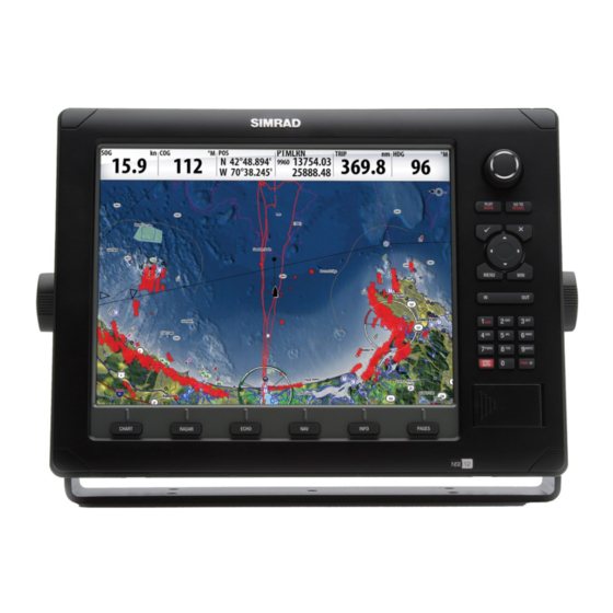
Multi-function display
Hide thumbs
Also See for NSE8:
- Operation manual (106 pages) ,
- Installation manual (88 pages) ,
- Quick reference manual (7 pages)

Related Manuals for Simrad NSE8


Summary of Contents for Simrad NSE8
- Page 1 Operation Manual Simrad NSE8 and NSE12 Multi-function Displays English www.simrad-yachting.com A brand by Navico - Leader in Marine Electronics...
- Page 3 E.U. and E.E.A. For more information refer to the separate NSE8/NSE12 Installation manual. About this manual This manual is a reference guide for operating the Simrad NSE8 and NSE12 systems. It assumes that all equipment is installed and configured, and that the system is ready to use.
- Page 4 References to keys on the operator panel are written in boldface, e.g. WIN key. The software This manual is written for Simrad NSE Release to Market 1 (RTM1). Please check web site for details on release version. MENU The About dialog above is an example only and may not match the sw installed on your unit! The manual will be continuously updated to match new sw releases.
-
Page 5: Table Of Contents
Contents Overview ..................7 Front panel ..................7 The NSE screen structure ..............8 Communicating with the NSE unit ............9 Basic operation ................11 Turning the unit on/off ..............11 Positioning a Man Over Board mark ........... 11 Adjusting the backlight..............12 Operating the menu system .............. - Page 6 The radar panel ................29 The radar operational modes ............30 Setting up the radar image ............... 30 Using the cursor on the radar panel ........... 31 Optimizing the radar image............... 32 Setting a guard zone around your vessel ..........33 Other vessels on the radar image ............
- Page 7 Waypoints/routes/tracks ..............56 Trip Log ..................57 Sun/moon ..................57 Tides ..................... 57 Files ....................57 Customizing your system .............. 59 Page setup ..................59 Adjusting panel size ................. 61 Setting the appearance of the instrument bar ........61 Changing system settings ..............62 Sirius audio and weather (North America only) ......
- Page 8 Blank page 6 | Table of contents...
-
Page 9: Overview
Overview Front panel PLOT GO TO MARK VESSEL MENU PQRS WXYZ STBY AUTO CHART RADAR ECHO INFO PAGES Direct Access Keys (DAK). Provide direct access to a page. Repeated presses of each DAK cycles through several different pages that relate to the DAK PLOT/MARK key. -
Page 10: The Nse Screen Structure
The NSE screen structure Pages and page groups The NSE screen is comprised of page groups, accessed by pressing one of the Direct Access Keys (DAK). CHART RADAR ECHO INFO PAGES Chart Radar Echosounder Navigation Info Utilities Each page group (except the Utilities pages) may include 5 pages. The first page in a page group will always be a full screen panel. -
Page 11: Communicating With The Nse Unit
In addition to these panels the following applications can be connected and displayed on other panels: Application Description AIS information as overlay on chart and radar panels Weather Weather graphics and data as overlay on chart panel. Sirius Weather application is available in North America only. Audio Satellite radio functions as a panel along the bottom of a page. - Page 12 Dialogs Dialogs are used for entering user input or for presenting information to the user. A dialog may be presented in full-screen, or as a popup dialog in the centre of the screen. Depending on type of information or entry, different keys are used to confirm, cancel and close the dialog.
-
Page 13: Basic Operation
Basic operation Turning the unit on/off POWER ON STAND BY POWER OFF If you turn the unit ON when no external equipment is connected you will be asked to run in simulator mode. When you turn ON the system after the first-time initialization, the system will start with the same page and with settings that were activated when the system was turned OFF. -
Page 14: Adjusting The Backlight
Adjusting the backlight The backlight for LCD and keys can be adjusted at any time independent of what is on the screen. MENU A night mode is included and optimized for low light conditions. Details on the chart may be less visible when the Night mode is selected! Operating the menu system Selecting menu item and confi... -
Page 15: Using The Cursor
Exiting the menu By pressing the X key the menu will return to previous menu level, and then exit. MENU Using the cursor The cursor is by default not shown on any panel. When you use one of the arrow keys on a Chart, Radar or Echosounder panel the cursor will become visible. -
Page 16: Working With Pages And Panels
Working with pages and panels Selecting pages You access a page group by pressing the corresponding DAK (Direct Access Key). CHART RADAR ECHO INFO PAGES Active DAK is indicated with a red symbol right above the key. When you press a DAK for the first time, the default page for that group is displayed. -
Page 17: Using The Simulator
3 Using the simulator Simulator mode MENU The simulation feature main data sources, so you can see how the unit works without being connected to echosounder, radar, GPS etc. You can use the simulator to help you become familiar with your unit before using it out on the water. - Page 18 Blank page 16 | Simulator...
-
Page 19: Using Charts
Using charts On the chart panel you can determine your vessel’s position in relation to land. You can use the chart display for planning routes and sailing along a predefined route. The chart function can also display your vessel’s position relative to other chart objects, plan and navigate routes, create waypoints;... -
Page 20: The Vessel Symbol
The vessel symbol When a GPS and a suitable compass sensor is connected to the system, the vessel symbol indicates vessel position and heading. MENU The vessel’s extension line can be activated to show course over ground. The length of the line indicate the distance that the vessel will travel with current speed in selected period. -
Page 21: Chart Scale
Measuring distance The cursor can be used to measure the distance between your vessel and a position or between 2 points on the chart panel. MENU Use the following process to measure a distance. Start the Measure function Move the cursor towards the second measuring point A line will be drawn from the vessel center to the cursor position, and the distance will be... -
Page 22: Positioning The Chart On The Panel
Positioning the chart on the panel Selecting chart center When the cursor is active on the panel, the chart will be centered around the cursor position (cursor mode). Pressing X key will remove the cursor, and the chart center will be positioned at the vessel (vessel mode). -
Page 23: Chart Categories
Radar and Sirius weather functions are described in separate sections in this manual. Chart data The NSE system can use Simrad and Navionics chart databases. MENU The Navionics chart includes options that not are available in the Simrad database. -
Page 24: Chart Options In Navionics Chart Database
Chart options in Navionics chart database Chart view MENU The Navionics chart database provides you with 2D and 3D view options. 2D presents chart information in a basic mapping mode, but with Navionics Platinum details. 3D provides a three dimensional graphical view of land and sea contours. - Page 25 The Photo overlay function is disabled as you zoom out beyond a certain level. Photo transparency The transparency sets the opaqueness of the photo overlay. MENU Optional settings for Navionics charts Annotation Determines what area information— such as names of locations and notes of areas—is available on display.
- Page 26 Contours depth Determines which contours you see on the chart down to the selected dontours depth value. 24 | Using charts...
-
Page 27: Waypoints, Routes & Tracks
Waypoints, routes & tracks Waypoints A waypoint is a mark positioned on a chart, on a radar image or on an echosounder image. Each waypoint has an exact position with latitude and longitude coordinates. A waypoint positioned on an echosounder image, will in addition to position information, have a depth value. -
Page 28: Tracks
Editing waypoints A waypoint can be edited in the Waypoint dialog. You can also move the waypoint manually by using the cursor; MENU Select the waypoint by resting the cursor over it Press the MENU key and select the move option Use the arrow keys to move the cursor to a new position Confi... -
Page 29: Routes
Routes A route consists of a series of waypoints entered in the order that you want to navigate them. When you rest the cursor over a route, it will turn blue and the route name will be displayed. Creating new routes by using the cursor You can create a new route on the Chart panel as follows: Press the PLOT key and select the new route option... -
Page 30: The Waypoints, Route And Tracks Page
The waypoints, route and tracks page The Utilities pages includes a Waypoints, Routes and Tracks page. This gives access to advanced edit functions and settings for all these items available on your system. There are several ways to access the library. A couple of them are illustrated below. You move between the tabs in the library by using the left/right arrow keys. -
Page 31: Using The Radar
Using the radar The radar panel can be set up as a full screen view or combined with other panels. The radar image can also be displayed as an overlay to existing 2D chart views and 3D for Navionics. Refer to the Chart section. The radar panel HEADING EADING... -
Page 32: The Radar Operational Modes
The radar operational modes The radar’s operational modes are controlled from the NSE unit. The following modes are available: MENU The power to the radar scanner is turned off Standby The power to the radar scanner in on, but the radar is not transmitting any signals. -
Page 33: Using The Cursor On The Radar Panel
Setting the radar orientation Heading up MENU Rotates the radar image to display the current heading directly up on the radar image. North up Rotates the radar image with the north direction upwards. Course up Rotates the radar image to display the current navigation course directly up. -
Page 34: Optimizing The Radar Image
Optimizing the radar image You may be able to improve the radar image by adjusting the radar sensitivity, and by filtering the signals from effect of random echoes from sea and weather conditions. The parameters are adjusted by using the rotary knob. You select between the control images by pressing the rotary knob. -
Page 35: Setting A Guard Zone Around Your Vessel
Setting a guard zone around your vessel A guard zone is a region (either circular or a sector) that you can define on the radar image. You can also define if an alarm is activated when a radar target enters or exits MENU the zone. -
Page 36: Target Tracking
Other vessels on the radar image If MARPA radar(s) or AIS devices are connected to the NSE system, any targets detected by these devices will be displayed as an overlay on the chart and on the radar image. You MENU can also see messages and position for DSC transmitting devices within range. - Page 37 EBL/VRM The electronic bearing line (EBL) is a line from the center of the vessel. The line’s bearing remains constant as the vessel moves. The variable range marker (VRM) is a user- MENU controlled range ring that surrounds the vessel. The EBL/ VRM function is used to measure distance and bearing from the vessel’s position to a target.
- Page 38 Blank page 36 | Using radar...
-
Page 39: Other Vessels On Chart And Radar Image
Other vessels on chart and radar image If MARPA radar(s) or AIS devices are connected to the NSE system, any targets detected by these devises can be displayed as an overlay on the chart. You can also see messages and position for DSC transmitting devices within range. You can define alarms to notify you if a target gets too close or if the target is lost. -
Page 40: How To Display Other Vessels
How to display other vessels MENU Selects which targets to display. Sets the length of the extension line for your vessel and for other vessels. The length of the extension line indicates the distance the vessel will move in the selected time period. -
Page 41: Target Alarm Settings
Target alarm settings You can define several alarms to alert you if a target comes within predefined range limits, or if a previously identified target is lost. MENU The following alarms can be set: Alarm ID Description Dangerous vessel Controls whether an alarm shall be activated when a vessel comes within the predefi... -
Page 42: Finding Other Ais Vessels
You can also display information about other vessels from the Vessels page as described in the Utilities pages section. MENU Finding other AIS vessels You can search for other vessels equipped with suitable AIS devices from your chart menu or from the Find or Vessels feature in the utilities pages (refer to the Utilities pages section). -
Page 43: Using The Echosounder
Using the echosounder The Echosounder function provides a view of the water and bottom beneath your vessel, allowing you to detect fish and examine the structure of the sea floor. The echosounder image The echosounder displays the water column moving from right to left on the panel. You can select between single panel view and several split views as described later in this chapter. -
Page 44: Setting Up The Sounder Display
Setting up the sounder display The echosounder panel can be setup as a single view, or with split view where the left and the right side presents different images. MENU Split screen options Zoom The Zoom mode presents a magnified view of the sounder image on the left side of the panel. -
Page 45: Using Colors
Setting the echosounder range The range setting determines the depth shown on the display. MENU Auto If you select Auto, the system will automatically display the whole range from the water surface to the bottom. Auto range will automatically be turned off once you adjust the range manually. Manually changing the range You can increase or decrease the range by pressing the zoom keys. -
Page 46: Using The Cursor On The Echosounder Panel
Using the cursor on the echosounder panel The cursor is by default not shown on the sounder image. When you press one of the arrow keys the cursor will be visible, the depth at the cursor position will be shown, the information window and the history bar will be activated. -
Page 47: Optimizing The Echosounder Image
Optimizing the echosounder image Several parameters can be adjusted to optimize the sounder image. Gain The gain controls the sensitivity of the echosounder. The more you increase the gain, the more details will be shown on the image. However, a higher gain setting may introduce more background clutter on the image. -
Page 48: Recording The Echosounder Data
Clarity Wave action, boat wakes and temperature inversion can cause on-screen clutter near the surface. MENU The surface clarity option reduces surface clutter by decreasing the sensitivity of the receiver near the surface. Recording the echosounder data You can record echosounder data and save the file internally in the HDS unit. You can select how many bytes per seconds that is to be used when saving the log file. - Page 49 Viewing the recorded sounder data The recorded sounder images are stored internally in the HDS unit, and can be reviewed when selected. MENU The log file is displayed as a paused image, and you get access to the replay and echo options by pressing the MENU key.
- Page 50 Blank page 48 | Using echosounder...
-
Page 51: Navigating
Navigating The navigation function included in the NSE allows you to navigate towards the cursor position, a position defined by latitude and longitude values, a waypoint or along a predefined route. For information about positioning waypoints and creating routes, refer the Waypoints, Tracks and Routes section. -
Page 52: Navigation Parameters
Navigation parameters Navigation method MENU Different methods are available for calculating the distance and bearing between any two points on a chart. The great-circle route is the shortest path between two points. However, if you are to travel along such a route, it would be difficult to steer manually as the heading would constantly be changing (except in the case of due north, south, or along the equator). -
Page 53: Navigation Panels
Navigation panels The Steer and Position panels can be used to display information when you are navigating. The Steer panel DATA FIELDS USE LEFT/ RIGHT ARROW TO TOGGLE COURSE VESSEL OFF COURSE LINE SYMBOL LIMIT Data fi elds The Steer panel offers the following information: Distance to destination Bearing to waypoint Speed over ground... - Page 54 Position panel Data fi elds Position in lat. and lon. Time and date Speed over ground Course over ground 52 | Navigating...
-
Page 55: The Instrument Panel
The instrument panel The instrument panel consists of multiple gauges — analog, digital and bar — that can be customized to display selected data. The instrument panel displays data on dashboards, and you can define up to ten dashboards within the instrument panel. MENU Switching between dashboards You switch between a panel’s dashboards by using the left and right arrow keys or by... - Page 56 Blank page 54 | Instruments...
-
Page 57: The Utilities
The utilities pages The utilities pages includes options and tools that are not specific to any panel. These pages act different to the chart, radar, echo etc. They are always full screen, and you cannot use them in a split page with any other panels. A utility page will open on top of your previous page. -
Page 58: Alarms
Alarms Active alarms List of active alarms. Alarm history List of all alarms with time stamp. Alarm settings List of all available alarm options in the system, with current settings. Satellites Status page for active satellites. Find Search function for several chart items. By pressing the MENU key you get access to available options for the selected item. -
Page 59: Trip Log
Trip Log Trip 1 / Trip 2 Displays voyage and engine information, with reset option for all data fi elds. Today Displays voyage and engine information for current date. All data fi elds will be automatically reset when the date changes. Sun/moon Displays sunrise, sunset, moonrise and moonset for a position based on entered date and the position’s... - Page 60 Blank page 58 | Utilities pages...
-
Page 61: Customizing Your System
Customizing your system Page setup Your NSE system includes a set of predefined pages for each page group accessed by the Direct Access Key (DAK). The list of available pages is displayed when you press the DAK for the active page. Each page group can have up to 5 pages, organized as single panels or as a combination of panels. - Page 62 RADAR MENU MENU 60 | Customizing your system...
-
Page 63: Adjusting Panel Size
Adjusting panel size You can adjust the size of the panels in a multi panel’s page by pressing the page group’s DAK. The illustration below shows how you change the size of a 3-panels Chart page. CHART MENU INFO Setting the appearance of the instrument bar Data sources connected to the system can be viewed in an instrument bar on top of your screen. -
Page 64: Selecting Language
Changing system settings The system settings menu provides access to advanced settings for your NSE unit and determines the way your NSE unit displays various MENU user interface information on the display. Selecting language When you select your desired language; all panels, menus and dialogs will change accordingly. -
Page 65: Sirius Audio And Weather (North America Only)
Sirius audio and weather (North America only) When connected to a Navico Weather Module MKII, you can subscribe and include Sirius audio and Sirius Marine Weather Service on your NSE system. Sirius audio and weather service covers inland US waters and coastal areas into the Atlantic and Pacific oceans, Gulf of Mexico and the Caribbean Sea. - Page 66 The radio channels list The channels list displays all available Sirius channels, whether or not you have a subscription for the channel. MENU Adding channels to favorites list You can create of list of your favorite channels from within the channels list. When a favorite list is available, you page through this list when you use arrow keys;...
-
Page 67: Sirius Weather
Sirius weather The Sirius weather option can be displayed as overlay to your chart panel. When activated, weather options become available in the Chart menu. MENU COLORED BAR * PRECIPITATION * FORECAST WIND BARBS * * Optional weather image items You turn the optional weather graphics on/off individually. -
Page 68: Weather Forecast
Weather forecast Selecting a marine forecast zone You can setup the system to read the forecast for a selected area. The context help in the dialog shows how to use the keys to select marine zone. If no area is selected the system will read the forecast for your current vessel position. Tropical statements You can read tropical statements including information about tropical weather conditions. -
Page 69: Using Video
Using video The video function allows you to connect optional cameras to your NSE system. The video images will not be shared with other NSE units via the network! The video panel The video panel is accessed via the INFO key. INFO The video panel can also be set up in one of the other page groups accessed by the DAK keys. -
Page 70: Optimizing The Video Image
Optimizing the video image You can optimize the video display by adjusting the video image settings. Default for all settings: 50%. Selecting video standard NSE supports NTSC and PAL video. The two channels are set up individually. Check the local video standard or the standard of your cameras. 68 | Video... -
Page 71: The Alarm System
The alarm system The NSE system will continuously check for dangerous situations and system faults while the system is running. When an alarm situation occurs, an alarm message will pop up on the screen. If you have enabled the siren, the alarm message will be followed by an audible alarm. The alarm is recorded in the alarm listing so that you can see the details and take the appropriate corrective action. -
Page 72: Customizing The Alarm Settings
Customizing the alarm settings The alarms can be setup in Settings tab in the Alarms page. This page also includes information about active alarms and alarm history. MENU The Alarms page can also be activated from the Utilities pages. MENU The alarms are described in the chapter describing the corresponding feature. -
Page 73: Maintenance
Simple maintenance procedures Cleaning the display unit Clean the housing and the front glass of the NSE8/12 unit with a damp cloth and mild detergent. Checking the keys Make sure that no keys are stuck in the down position. However, if one is stuck, wiggle the key to free it back to normal. - Page 74 MENU 72 | Maintenance...
-
Page 75: Menu Overview
Menu overview Settings menus System Fuel Tracks Chart Alarms Units Echo MENU Network Radar Vessels Navigation Simulator Menu overview | 73... -
Page 76: Context Menus
Context menus Goto menu Chart PLOT GO TO MARK VESSEL MENU Radar Echo Info Plot menu PLOT GO TO MARK VESSEL 74 | Menu overview... -
Page 77: Index
Index Color palettes 29 Color templates 41 AIS 15, 53 AIS devices 32 Compass 18 Context help 11 AIS targets 15 Context menu 7 Alarm messages 8 Alarms 53 Contours 22 Coordinate system 48 Active alarms 53 Alarm history 53 Course extension line 35 Alarm settings 53 Course over ground... - Page 78 Menu key 5 MENU key 37 File management system 55 MMSI messages 36 Filtering the signals 30 MOB 49 Find 54 MOB function 9 Freeze the sounder image 39 Moving targets 29 Gain 30 Navigate routes 15 Auto and Manual 30 Navigating 47 Color 43 Navigating function 7...
- Page 79 Off 28 Sounder frequency 41 Standby 28 Sounder panel 40 Transmit 28 Sounder range 41 Radar orientation 29 Auto 41 Heading up 29 Manually changing the range 41 North up 29 Source fi les 13 Course up 29 Speed over ground Radar overlay 33 SOG 49, 50 RADAR page 57...
- Page 80 Video input channels 65 VRM function 33 Water column 39 Waypoint 23 Positioning 24 Positioning on echo sounder image 23 Waypoint dialog 23 Waypoints, routes and tracks 54 Weather 7 Weather conditions 30, 63 Weather forecast 64 Weather icons 63 Weather image 63 Weather overlay 63 Weather overlay transparency 63...
Need help?
Do you have a question about the NSE8 and is the answer not in the manual?
Questions and answers
how change boat name in the AIS transponder