Table of Contents
Advertisement
Quick Links
Thank you to choose inverter of DEMA Electric Co., Ltd.
D6 series inverter is the product developed by the DEMA Electric Co., Ltd, which is characterized with high
performance, multiple functions and high quality. They apply technology platform with high performance,
modular system structure and programmable units which make them with various application scope and
strong adaptability.
Errors in installation, wiring and operation may cause accidents, shorten the inverter's life and degrade its
performance. Therefore the operators must carefully read and understand this manual before using the
inverter, master the right operation method.
This operation manual must be properly safekept by operator of the machine.
If you have any unclear problems during operation or excellent performance of the inverter isn't played role,
please refer to this manual.
This manual is applicable to following members of D6 series:
D6B: General inverter with high functions, with open/close loop control, torque control and multiple-application
control mode (including PID, wobbling frequency etc), applicable to very extensive application field.
D6L: General light load type multi-functional inverter, open loop no PG vector control, applicable to light load
constant torque or fan pumps loading applications whose overload capacity demand isn't high.
D6P: Flat plate through-wall installation type inverter, open loop no PG vector control, applicable to light load
constant torque or fan pumps loading applications whose overload capacity demand isn't high.
Version number: 1.4
Date: 2013-10-24
DEMA electric cooperation is not responsible for the mistakes in this manual, and reserve the rights to renew
production without informing.
Attentions:
Please read this operation manual carefully, understand each contents, so that you can carry out right
installation, wiring, operation and maintenance.
Use inverter only after be familiar with knowledge, safe information and all attentions of the inverter..
This manual should be reserved by actual user.
The safety levels are divided into ― Danger‖ and ― Warning‖ in this manual, please use the following mark
respectively:
: It may cause death or serious injure of personnel if it isn't operated according to
requirements.
: It may cause moderate damage or minor injuries of personnel, or property damage if it
isn't operated according to requirements..
Please be sure to eep the contents marked with safety sign. Because the situation is different, items
marked by ― Warning‖ may also cause serious results, please follow these two level attentions.
Advertisement
Table of Contents

Subscribe to Our Youtube Channel
Summary of Contents for Dema Electric D6 Series
- Page 1 Thank you to choose inverter of DEMA Electric Co., Ltd. D6 series inverter is the product developed by the DEMA Electric Co., Ltd, which is characterized with high performance, multiple functions and high quality. They apply technology platform with high performance, modular system structure and programmable units which make them with various application scope and strong adaptability.
- Page 2 English term and abbreviations ASR: Automatic Speed Regulator AVR: Automatic Voltage Regulation AI: Analog Input AO: Analog Output DI: Digital Input DO: Digital Output EMI: Electric Magnetic Interference LED: Light Emitting Diode MOP: Motor Operated Potentiometer PULS: Pulse Input PYO: Pulse Frequency Output PID: Proportional Integral Derivative PG: Pulse Generator PWM: Pulse Width Modulation...
-
Page 3: Table Of Contents
Contents 1 SAFETY PRECAUTIONS .............................. 1 1.1 INSTALLATION ................................ 1 1.2 WIRING .................................. 1 1.3 OPERATION ................................1 1.4 MAINTENANCE ..............................2 1.5 DISPOSAL ................................2 1.6 APPLICABLE SCOPE OF PRODUCT ........................... 2 2 INSTALLATION AND WIRING ............................. 3 2.1 CHECK UPON DELIVERY ............................3 2.2 NAMEPLATE DESCRIPTION ............................. - Page 4 3.1.3 D ........................22 ESCRIPTION OF DISPLAY FUNCTION 3.1.4 U ..............................23 NITS INDICATION 3.1.5 R ............................23 UN STATUS INDICATIONS 3.2 DISPLAY STATUS OF OPERATION KEYPAD OF INVERTER ..................23 3.2.1 S ................................23 TOP STATUS 3.2.2 R ................................23 UN STATUS 3.2.3 A ..............................
- Page 5 4.16 DIGITAL OUTPUT TERMINALS ..........................51 4.17 TWO/THREE-LINE OPERATION CONTROL ......................54 4.18 SPEED CONTROL OPERATION MODE ........................56 4.19 TORQUE CONTROL OPERATION MODE ......................59 4.20 PROCESS PID CONTROL ............................63 4.21 WOBBLE FREQUENCY ............................68 4.22 ASR (SPEED REGULATOR AND CURRENT REGULATOR) ..................71 4.23 AVR FUNCTION ..............................
- Page 6 8.2.1 N ................................ 115 OISE ILTER 8.2.2 C ............................115 URRENT LEAK PROTECTOR 8.2.3 B ..............................115 RAKING RESISTOR 8.2.4 AC ................................ 116 REACTOR 8.2.5 DC ................................ 116 REACTOR 8.2.6 E ..............................117 XTENDED CABLE 9 STANDARD SPECIFICATIONS ..........................118 9.1 STANDARD SPECIFICATIONS ..........................
-
Page 7: Safety Precautions
1 Safety Precautions 1 Safety Precautions You must carefully read the following contents before installation, wiring, operation and maintenance of the product, and operate strictly according to notes. 1.1 Installation Install the inverter on a nonflammable object such as metal etc. Otherwise, there may be a risk of fire. Do not install the inverter in an environment with inflammable gases which may cause explosion. -
Page 8: Maintenance
1 Safety Precautions Only when the cover board has been attached, the power can be switched on. Otherwise, there may be a risk of electric shock. Do not touch main circuit terminal of the inverter when electrical power is going to the inverter even if the inverter is in stop state. -
Page 9: Installation And Wiring
2 Installation and Wiring 2 Installation and Wiring 2.1 Check upon delivery Please check the following items when the inverter is firstly packed: ◆ Whether the product is damaged during shipping. ◆ Read data on the nameplate conform whether type and specification of the product are in accordance with your order. -
Page 10: Installation Of Inverter
2 Installation and Wiring 2.4 Installation of inverter 2.4.1 Ambient condition Environment temperature range of inverter: -10℃~50℃. When the ambient temperature is higher than 50℃, please choose well ventilated place and decrease the inverter by 10% for every 5℃ increment. 2.4.2 Installation site ◆No corrosive, flammable or explosive gases or liquids. -
Page 11: Appearance And Installation Size
2 Installation and Wiring 2.4.4 Appearance and installation size Outline size and approximate weight of inverter: Code Diameter of of box Outline Inverter type installation (mm) (mm) (mm) (mm) (mm) (kg) body hole(mm) D6B-0.4S2 D6B-0.75S2,D6B-0.75T4 D6B-1.1S2,D6B-1.1T4 D6B-1.5T4 D6B-2.2T4 D6B-3.0T4 D6L-0.75T4 D6L-1.1T4 D6L-1.5T4 D6L-2.2T4... - Page 12 2 Installation and Wiring Code Diameter of of box Outline Inverter type installation (mm) (mm) (mm) (mm) (mm) (kg) body hole(mm) D6B-7.5T4,D6H-5.5T4 D6B-11T4,D6H-7.5T4 D6L-11T4 D6B-15T4,D6H-11T4, D6L-18.5T4 D6B-18.5T4,D6H-15T4, 11.2 D6L-22T4 D6L-15T4 D6B-22T4,D6H-18.5T4 15.3 D6B-30T4, D6H-22T4, D6L-37T4 D6L-30T4 15.2 D6B-37T4, D6H-30T4, D6L-45T4 D6B-45T4,D6B-55T4,...
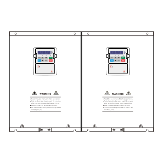
- Page 13 2 Installation and Wiring Appearance A: Appearance B:...
- Page 14 2 Installation and Wiring Appearance C:...
-
Page 15: Removal And Installation Of Operation Keypad
2 Installation and Wiring Appearance D: 2.5 Removal and installation of operation keypad 2.5.1 Appearance and size of operation keypad 2.5.2 Appearance and size of standard operation keypad installation box The keypad box is generally used on motor which power is more than 15kW, it is also used on the installation operation keypad of the cabinet. -
Page 16: Direct Installed Type Operation Keypad
2 Installation and Wiring 2.5.3 Direct installed type operation keypad Direct installed type operation keypad is directly installed on the keypad of the machine cabinet and not be installed through the installation box. Appearance size figure: The customer can get special extension line and control panel for connection of direct installed type operation panel on request. -
Page 17: Installation And Removal Of Operation Keypad
2 Installation and Wiring The installation box shall be connected with the control board with 6 cores cables and control board, shown as following figure: 2.5.5 Installation and removal of operation keypad ◆ Removal Place finger on clamp parts at left and right of the operation panel, impose force upward from the middle at same time and pull out the operation keypad. -
Page 18: Installation Of Keypad On Cabinet
2 Installation and Wiring 2.5.6 Installation of keypad on cabinet front cover The keypad of D6B/L inverter can be taken off from the inverter and installed on the front cover of the cabinet, the keypad and inverter are connected by the extension line (Manufacturer can offer specifications of 1.5 meters ~ 30m). -
Page 19: Wiring Of Inverter
2 Installation and Wiring 2.6 Wiring of inverter 2.4.1 Basic wiring diagram of inverter The user must properly connect according to following basic wiring diagrams, user can choose the control terminal according to demand. -
Page 20: Wiring Specifications
2 Installation and Wiring 2.4.2 Wiring specifications Selection of copper-core insulation wires and incoming breaker (parameters in table are recommended value): Incoming Main circuit Control circuit switch Inverter model circuit Input Output Control Terminals Grounding Terminals breaker cable cable cable screws cables(mm2) screws... -
Page 21: Main Circuit Terminals
2 Installation and Wiring 2.4.3 Main circuit terminals ◆ Introduction of main circuit terminals Terminals symbols Terminals name Description To 3-phase power supply(50/60Hz): three phases 380V ac or single-phase L1/R、 L2/S、 L3/T Input of power supply 220Vac Signal-phase input fromL1,L2,L3 impending. U、V、W Inverter output terminal To 3-phase motor... - Page 22 2 Installation and Wiring cause electricity undesirable contact and wire easy to fall off. If there is a redundant bare part please make sure package it by insulation tape. For safety (prevent electric shocks and fire) purpose and reduce noise, this terminal must be securely grounded with the grounding resistance less than 100Ω,strictly accordance with the national electrical code.
-
Page 23: Control Circuit Terminals
2 Installation and Wiring To suppress the interference generated by the inverter with other devices, it is recommended to place the output cables (U, V, W) in a grounded metal conduit, the distance between metal conduit and control line must be more than 50cm. - Page 24 2 Installation and Wiring Terminals name Function and description Technical specifications resolution: 12 bits A/D Output voltage: -10V~10V Load current: ≤10mA Analog output, function programmable Refer to chapter 4.14 Output current: 0~20mA Max output voltage:11V Digital input terminal,Function programmable Common terminal: XC Refer to chapter 4.15 to select function High level:...
- Page 25 2 Installation and Wiring Terminals name Function and description Technical specifications The user needs to order Y3 and Y4 from the maker SJ1 switch over setting Switch Switch Function Description number name When switch is on: connect a 120Ω resistance between +485 and -485 communication of inverter interior communication terminal 485.
- Page 26 2 Installation and Wiring Control terminals connection notes: Wire dispose: Unwrap the wire skin according to the following size, if wire stripping is too long it will cause short-circuit, if it is too short, it will cause electricity undesirable contact and wire easy to fall off. Recommend to use shorter than 0.9mmstick terminal.
- Page 27 2 Installation and Wiring In addition, when the input analog signal is interference, also can increase function parameters 10_06 (AI1 filtering time) or 10_07 (AI2 filtering time) to filter out interference, but the value should not be too high, avoid to influence too much on the control response speed.
-
Page 28: Operation Description Of Inverter
3 Operation Description of Inverter 3 Operation Description of Inverter 3.1 Name and description of each part of operation panel 3.1.1 Appearance of operation panel 3.1.2 Description of key function Key appearance Key name Function description ENTER Enter menu, enter parameters or affirm one parameter written. Return the status that before press ―ENT ‖... -
Page 29: Units Indication
3 Operation Description of Inverter Display Display Description Description contents contents Parameters write is end Parameters are being uploaded Password check error, Parameters are being downloaded Parameters setting error Ex-work setting values are being recovered Normal 3.1.4 Units indication Three unit lights could display unit groups as shown in the below chart. Unit light symbols Unit Description... -
Page 30: Abnormal Status
3 Operation Description of Inverter 3.2.3 Abnormal status When the inverter is abnormal, LED will display relevant abnormal code (refer to chapter 7) , press ―ST O P/RESET‖ or through multi-function digital input terminals reset inverter after abnormal is removed. 3.2.4 Parameter editing status Press ―ENT E R‖... -
Page 31: Speed Adjust
3 Operation Description of Inverter 3.3.3 Speed adjust When monitoring parameter of operation panel is set at 14_01 (setting speed) , operation panel key ―UP ‖ and ―DO WN‖ can regulate the setting speed. When is select 14_00 (run speed) , operation panel key ―UP‖ and ―DO WN‖... -
Page 32: Jog Run Operation Mode Of Inverter
3 Operation Description of Inverter and reverse function through input switch signals or pulse signal to this two terminals. 3.5 Jog run operation mode of inverter Jog run operation can be realized on operation panel, control terminals and serial communication terminals. System is in the speed control pattern when it is on jog operation, jog speed is set by 01_22, jog run acceleration and deceleration time each set by 01_23 and 01_24. -
Page 33: Setting Common Parameters Of Each Control Mode
3 Operation Description of Inverter 3.7.1 Setting common parameters of each control mode Set 08_00~08_05 according to motor nameplates parameters; Set the motor protection parameters 12_11; Choose suited motor drive mode (00_12) and application control mode (00_13) according to application requirements and conditions;... -
Page 34: Description Of Function Parameters And Setting
4 Description of function parameters and setting 4 Description of function parameters and setting 4.1 Environment and parameters management 00_00 Setting range and description Ex-work setting Change Addr 0000~9999 Setting user password 0000 ○ 0000H 0000 means no password Set 00_00 to a number of four bits incomplete equal to 0, press down ― ENTER‖ or no key pressing acts during two minutes, Password protection is effective. - Page 35 4 Description of function parameters and setting 00_07 Setting range and description Ex-work setting Change Addr Boot pre-show choice 0007H 00_08 0008H 00~38 Quick display parameter selection 1 00~38 correspond to parameters 00_09 × numbers of data monitoring parameters 0009H Quick display parameter selection 2 group (14_XX) .
- Page 36 4 Description of function parameters and setting ◆ASR parameters must be properly set to ensure the steady-state performance and dynamic performance of speed control. ◆It is recommended that the motor pole number not be greater than eight; ◆Vector control not be used for double-cage motors, current-displacement motors or torque motors. 00_13 Setting range and description Ex-work setting...
-
Page 37: Speed (Frequency) Limitation
4 Description of function parameters and setting In where: T1=01_22×01_23÷01_01, T2=01_22×01_24÷01_01. 4.2 Speed (frequency) limitation Relevant function parameters: 01_00 Setting scope and description Ex-work setting Change Addr Minimum operation speed 0~01_01 rpm × 0100H 01_01 01_00~19500 rpm 1500 × 0101H Maximum operation speed 01_00 and 01_01 set minimum and maximum rotation speed necessary for the inverter, they also set minimum and maximum output frequency of the inverter, sliding differential compensation may cause actual... -
Page 38: V/F Curve
4 Description of function parameters and setting Basic frequency voltage (Rated voltage of electric motor ) The output frequency and voltage of the inverter shall match rated value of the electric motor during setting basic frequency and basic voltage. When rated frequency of the electric motor is 50 Hz and set 08_03(basic frequency) less than 50 Hz, it may cause the electric motor damaged, when set 08_01(basic frequency voltage) exceeds rated voltage of the electric motor, it may cause the electric motor damaged 4.4 V/F curve... -
Page 39: Torque Compensation
4 Description of function parameters and setting 1.5 times curve, 1.7 times curve, 2 times curve and 3 times curve are applicable to fan and water pump etc which don’t need large torque under low speed, energy saving effect is good under low rotation speed because output voltage is low and noise is less. -
Page 40: Vector Control Current Loop And Rotation Differential Compensation
4 Description of function parameters and setting Automatic torque promotion function shall real-time change value of output voltage according to load current so as to automatically adopt various load conditions and output applicable voltage, realize great torque output under heavy load and small output current on no-load. Automatic torque promotion will automatically compensate voltage drop of stator resistor of electric motor, output voltage is increased. - Page 41 4 Description of function parameters and setting 01_02 Setting range and description Ex-work setting Change Addr 0: Start from starting frequency Starting mode 1: First dc brake then start from starting frequency × 0102H 2: Speed tracking starting 01_03 0.00~60.00 Hz 0.50 ○...
- Page 42 4 Description of function parameters and setting The starting frequency is mainly used to regulate the starting torque. When it has been set too high, the starting current would significantly increase, and the inverter would be produced because of over-current. And it can not work when the speed instruction is less than the speed determined by the starting frequency.
-
Page 43: Acceleration And Deceleration
4 Description of function parameters and setting Instruction: when the digital input 20(instruction of DC braking) is valid, and the speed is lower than the starting speed of DC braking in the stopping process, the inverter stops in the DC braking mode, whose time is not affected by 01_10(the time of Dc braking),which ends until lifting the instruction. - Page 44 4 Description of function parameters and setting 0.00~600.00 s 01_17 0.00 means emergency braking using free 0.00 ○ 0111H Emergency stop deceleration time stop mode 01_18 0.20 0112H S curve acceleration starting period time 01_19 0.20 0113H S curve acceleration ending period time 0.00~10.00 s ×...
-
Page 45: Locking The Operation Direction
4 Description of function parameters and setting Instruction: when using S-curve acceleration and deceleration, the total time will extend, its formula is: total acceleration time=no setting s-curve acceleration and deceleration time + (starting time + end time)/2 If not setting s-curve acceleration and deceleration time is shorter than the sum of starting time and end time, then Total acceleration and deceleration time=starting time+ end time Instruction: if selecting S-curve acceleration and deceleration mode, and the time changed in the operation,... -
Page 46: Brake Unit
4 Description of function parameters and setting (targets speed reached) issue instructions. 01_27 is used to judge whether setting speed is reached. When the motor speed is greater than the setting value of 01_27 SDT (speed detection level) when signal is effective, until the speed drops off to 01_28 lower than 01 _27 SDT signal is ineffective. -
Page 47: Dangerous Speed
4 Description of function parameters and setting quick downtime. When dc bus voltage is more than 01 _31 (brake unit used), brake unit will automatic put into use. According to 01 _30 (brake utilization rate), 01 _32 (braking resistance tolerance) and 01 _33 (braking resistance power) ,frequency converter will automatically put restrictions on the braking resistance of power consumption. - Page 48 4 Description of function parameters and setting 10_01 0A01H AI2 analog input type 10_02 100.0 0A02H AI1 gain 0.0~1000.0 % ○ 10_03 100.0 0A03H AI2 gain 10_04 0.00 0A04H AI1 bias -99.99~99.99 % ○ 10_05 0.00 0A05H AI2 bias 10_06 0.100 0A06H AI1 prop filter...
- Page 49 4 Description of function parameters and setting Mold Output calculation formula Curve diagram Otput=-gain*input+100%+bias While gain=100%, bias=0: Analog input 10~0V is Corresponding to 0~100% command output Otput=gain*2*(input-50%)+bias While gain=100%, bias=0: Analog input 0~10V is Corresponding to-100~100% (with 5V zero point) command output Otput=gain8(-2)*(input-50%)+bias While gain=100%, bias=0: Analog input 10~0V is...
- Page 50 4 Description of function parameters and setting enhance anti-jamming performance; Conversely, reduce filtering time will make response faster, but anti-jamming performance becomes poor. PULS (pulse frequency input) : Frequency converter takes the input pulse frequency and duty cycle as a given speed or PID given instructions etc.
-
Page 51: Analog Output Terminals
4 Description of function parameters and setting 4.14 Analog output terminals Related function parameters: Ex-work 10_13 Setting range and description Change Addr setting 0: Running speed (as 01_01 for 100%) AO1 terminals output function 0A0DH 1: Output frequency (as 01_01 corresponding frequency for 10_14 0A0EH 100%) -
Page 52: Digital Input Terminals
4 Description of function parameters and setting 10_24 0~50000 Hz ○ 0A18H 0% Command corresponding PYO pulse frequency 10_25 0~50000 Hz 10000 ○ 0A19H 100%Command corresponding PYO pulse frequency 10_26 0.0~100.0 % ○ 0A1AH 0% Command corresponding PYO duty ratio 10_27 0.0~100.0 % 100.0... - Page 53 4 Description of function parameters and setting 09_01 0901H X2 Digital input terminals function 09_02 0902H X3 Digital input terminals function 09_03 0903H X4 Digital input terminals function 09_04 0904H X5 Digital input terminals function 09_05 0905H X6 Digital input terminals function 09_06 0906H X7 Digital input terminals function...
- Page 54 4 Description of function parameters and setting 14~15: Reserved 37:Wobble frequency injection 16:Accel/decel time 1/2 switched 38:Opposite phase wobble sync input 17:Jog forward 39:Wobble state reset 18:Jog reverse 40:Programmable timer 1 reset 19:3-wire stop command 41:Programmable timer 2 reset 20:DC braking stop command 42:Programmable counter reset 21:Pre-excitation 43:PLC mode chooses 0...
- Page 55 4 Description of function parameters and setting select 03_05 select 03_06 select 03_07 select 03_08 select 03_09 select 03_10 Function 12 & 13: multistage torque selection signals Through the combination of 12 & 13, can define at most 4 periods torque (defined by 04_00~04_04) run curve.
- Page 56 4 Description of function parameters and setting MOP output a percentage, when speed is to given, maximum operation speed as 100%,in addition can also be used as the PID given, etc. MOP operation speed defined by 09_11. Twenty-fifth function (MOP save) signal is effective when it has a rise along action or power lost, will the value of MOP will be saved to 02_18.
-
Page 57: Digital Output Terminals
4 Description of function parameters and setting 4.16 Digital output terminals Related function parameters: Ex-work 09_12 Setting range and description Change Addr setting Y1 Digital output terminals function 090CH 09_13 0~44 090DH Y2 Digital output terminals function Corresponding function look up digital output ×... - Page 58 4 Description of function parameters and setting Digital output terminals function selection table: 0:Inverter ready 23:X3(after positive & negative logic) 1:Inverter running (DON) 24:X4(after positive & negative logic) 2:Exception stop 25:X5(after positive & negative logic) 3:Exception alarm 26:X6(after positive & negative logic) 4:External fault trip 27:X7(after positive &...
- Page 59 4 Description of function parameters and setting 3: abnormal warning The inverter sending abnormal warning signal is effective. 4: external abnormal stop The signals are effective when external abnormal causing inverter stop, and the signal is void as external fault restoration. 5: motor overloaded detection Make reference to the specification of inverter and motor protection.
-
Page 60: Two/Three-Line Operation Control
4 Description of function parameters and setting 37: specified count value to counter Make reference to the specification of programmable function units. 38: feedback limit output Make reference to the specification of process PID control. 39: the lower output feedback Make reference to the specification of process PID control. - Page 61 4 Description of function parameters and setting 03_02 Mode name Control logic Diagram 2 (FRC) 1 (RUN) run command invalid invalid stop Two-line type operation invalid effective forward mode 2 effective invalid stop effective effective reversal B1: operation key (open) Two-line type operation B2: stop key (closed) mode 3...
-
Page 62: Speed Control Operation Mode
4 Description of function parameters and setting 03_02 Mode name Control logic Diagram operation switch, effectively run Single line type operation Note: direction is determined by speed mode direction 4.18 Speed control operation mode Speed control channels Related function parameters: Ex-work 03_00 Setting range and description... - Page 63 4 Description of function parameters and setting 07_11 0: allow 1: ban × 070BH High speed resolution set enable The source of speed instructions basically has the following kinds: 1. jog speed; 2、output of process PID; 3、multi-step speed; 4、ordinary speed given (given by 03_00 appointed options) . The above speed Instruction channel given has below priorities: supreme……………………………………←……………………………………lowest jog speed……………output of process PID………multi-step speed………ordinary speed given.
- Page 64 4 Description of function parameters and setting 03_40 0~100 % (take 01_01 as 100%) × 0328H corresponding to 03 _41 set time speed decreases Speed decreases 03_41 1~65535 s × 0329H actual time =03_41×time rate (determined by 03_38) Speed reduce setting time Function of speed timing reduce fixed can add a correction that decreasing as time increase on basic speed instructions, working situation shown as below:...
-
Page 65: Torque Control Operation Mode
4 Description of function parameters and setting 4.19 Torque control operation mode Related function parameters: Ex-work 04_00 Setting range and description Change Addr setting 0: AI1×2.0 1: AI2×2.0 2: PULS×2.0 3: Set by 04_01~04_04 4: Serial terminals given Torque instructions given channel ○... - Page 66 4 Description of function parameters and setting 02_10 195.0 ○ 020AH Positive regeneration torque limit 02_11 195.0 ○ 020BH Reverse electric torque limit 02_12 195.0 ○ 020CH Reverse regeneration torque limit Torque control is a operation mode according to torque command control motor torque, torque control mode is only applicable to the motor control mode using the situation of the vector control Torque control mode needs to set 00_13 (apply control mode) as 4 (torque control mode) or 5 (speed/torque control mode) , when set as 5, Through the digital input terminals 27 (Hybrid control mode S_T, S_P mode...
- Page 67 4 Description of function parameters and setting Torque timing reduce fixed function can add a correction that reducing as time increase to the basic torque instructions. Working situation shown as below: Torque bias function Ex-work 02_13 Setting range and description Change Addr setting...
- Page 68 4 Description of function parameters and setting 02_16 0.000~5.000 1.000 ○ 0210H Braking torque bias gain 02_17 0.000~1.000 s 0.000 ○ 0211H Torque bias starting time The function of torque bias is input a certain torque to balance torque of loads before starting the motor,avoiding and decreasing the impaction caused by the existed torque when motor starts up.
-
Page 69: Process Pid Control
4 Description of function parameters and setting 4.20 Process PID control Ralative function parameters: Ex-work 00_13 Setting range and instruction Change Addr setting 0: Speed control mode 1: PID control mode 2: Wobble frequency control mode 3: customization control mode Application control mode ×... - Page 70 4 Description of function parameters and setting 06_12 06_13~100.0 % 100.0 ○ 060CH PID upper limit 06_13 -100.0~06_12 % ○ 060DH PID lower limit 06_14 06_12~06_13 % ○ 060EH PID preset 06_15 0.0~3600.0 s × 060FH PID preset holding time 06_16 0.0~100.0 % 100.0...
- Page 71 4 Description of function parameters and setting Process PID can be used for the control of process variables such as pressure, flowrate, liquid level, temperature and tension. Process PID can be used for the control of process variables such as pressure, flowrate, liquid level, temperature and tension.
- Page 72 4 Description of function parameters and setting 06_10 PID regulation characteristic: ―Po sitive‖ means when the setpoint is increased the speed is required to be increase; while ― negative‖ means when the setpoint is increased the speed is required to be lowered. Integral regulation: For the situations that require quick response , it is recommended to set 06_12 and 06_13 to the top and bottom limitation.
- Page 73 4 Description of function parameters and setting Process PID has three types of correction mode: reference frequency correction prior to accel/decel, reference frequency correction after accel/decel, and torque correction. These correction modes make it convenient to use the inverter in master-slave synchronous control and tension control. The figure below shows an instance of a given speed correction: Given speed correction prior to accel/decal slope: PID adjusted output (the maxium operation speed is 100%)of process preset and feedback is added to the given speed prior to accel/decal slope to correct the...
-
Page 74: Wobble Frequency
4 Description of function parameters and setting 4.21 Wobble frequency Wobble function is specially designed for winding yarns; it ensures that the yarns are wound around the spindle smoothly and evenly. If you set 00_13 = 2 (Wobble frequency control mode ) ,you can use the Wobble frequency control function. Correlation function parameters: Ex-work 00_13... - Page 75 4 Description of function parameters and setting 0: No action 03_38 1: Action, Select the time ratio 1 × 0326H Speed time to reduce correction 2: Action, Select the time ratio 10 03_39 0~44 × 0327H The same meaning as 09_12 Time to reduce correction control input 03_40 0~100 % (以01_01为100%)
- Page 76 4 Description of function parameters and setting 03_35 (Rising time) : sets the time for the rising edge. Actual rising time=03_34×03_35(s). Actual falling time=03_34×(1- 03_35) (s) 03_36 (Wobble randomness) : When 03_35 is not equal to zero, the actual rising time will vary randomly within a certain range, while the wobble period remain unchanged.
-
Page 77: Asr (Speed Regulator And Current Regulator)
4 Description of function parameters and setting 4、The base speed wobble frequency are from multi- stages speed and general speed .when jog and closed-loop speed operation, wobble function is automatically canceled . 5、It is forced to use ramp acceleration and deceleration during transiting to wobble base speed. Textiles winding Speed time to reduce correction can superimpose correction on the wobble base speed , the wobble frequency base speed decreases with time increasing, working as shown below :... - Page 78 4 Description of function parameters and setting 03_22 0.0~20.0 % (01_01=100%) × 0316H Used for PG V/F control only. ASR output frequency limit 03_42 0~2000 1000 ○ 032AH Current loop proportionality factor 03_43 0~6000 1000 ○ 032BH Current loop integral coefficients 03_44 10.0~300.0 % 100.0...
-
Page 79: Avr Function
4 Description of function parameters and setting 03_21 performs the differential operation on the reference frequency which has been accel/decel treated to obtain a feedforward torque reference, which in turn is added to the reference torque, thus helping the operating frequency better track the reference frequency during accel/decel and reduce the overshoot. ASR adjustment method : Select the appropriate ASR switching frequency. -
Page 80: Stall Prevention
4 Description of function parameters and setting When decelerating, time to close AVR functioin is less than deceleration time of AVR action mode, and deceleration current is slightly large. If the load rotation inertia is very large, the failure to actuate of AVR during deceleration will lead to heating radiation of generator. - Page 81 4 Description of function parameters and setting During deceleration, when the output current is greater than deceleration prevention overcurrent stalling level, the deceleration stops temporarily. After recovering the current, continues to decelerate. See diagram below. Constant-speed overcurrent stall prevention: During constant-speed running, when the output current is greater than the level of preventing overcurrent stalling during constant speed operation, the motor decelerates according to the set deceleration time.
-
Page 82: The Droop Mechanical Characteristic
4 Description of function parameters and setting Description: Deceleration overvoltage stall function is disabled automatically when inverter braking unit is working. 4.25 The droop mechanical characteristic Correlation function parameters: 03_23 Setting range and instruction Ex-work setting Change Addr Droop level 0.0~100.0 % (01_01=100%) ○... -
Page 83: Fault Auto Reset
4 Description of function parameters and setting 4.26 Fault auto reset Correlation function parameters: Ex-work 12_28 Setting range and instruction Change Addr setting 0~10 Note: Inverter module protection and external Auto reset times × 0C1CH abnormalities have not automatic reset function. 12_29 1.0~30.0 s ×... - Page 84 4 Description of function parameters and setting Ex-work 07_00 Setting range and instruction Change Addr setting 0.4~15 kW: 2000~15000 Hz, ex-work setting 8000 Hz 18.5~30 kW: 2000~12000 Hz, ex-work setting 4000 Hz Depends Carrier frequency ○ 0700H 37~90 kW: 2000~8000 Hz, ex-work setting on model 3000 Hz 110 kW above: 2000~6000 Hz, ex-work setting...
-
Page 85: Cooling Fan Control
4 Description of function parameters and setting however, it must be disabled when the load resistance component is big and motor cable is overlong. 4.28 Cooling fan control Correlation function parameters: Ex-work 07_08 Setting range and instruction Change Addr setting 0: Keep running 1: Controlled by the inverter ―r un / stop‖... -
Page 86: Restart After Momentary Power Stop
4 Description of function parameters and setting 4.29 Restart after momentary power stop Correlation function parameters: Ex-work 12_21 Setting range and instruction Change Addr setting 0: free shutdown and report the undervoltage fault (AE.dcL) 1:free shutdown, and restart if the voltage resumes within the time set by 12_23 or report the undervoltage fault(AE.dcL) if undervoltage time exceeds the time set by 12_23. -
Page 87: Inverter And Motor Protection
4 Description of function parameters and setting shutdown caused by momentary power failure for large-inertia loads like fans and centrifuges. Instruction: During momentary power failure restoration, the motor do not report the fault. 4.30 Inverter and motor protection Correlation function parameters: Ex-work 12_00 Setting range and instruction... - Page 88 4 Description of function parameters and setting 12_16 0.0~100.0 % (inverter rated current=100%) 30.0 × 0C10H Inverter underload protection level 12_17 0.0~100.0 s × 0C11H Underload protection detection time 12_18 0: No action 1; Keep running with alarming―AE. oHL‖ × 0C12H Motor temperature protection 2: Coast to stop with alarming―AE.o HL‖...
- Page 89 4 Description of function parameters and setting 12_10 selects 0, when the insufficiency of inverter heat dissipation at slow speed can be compensated. 12_11 (1min overload protection value): when the motor under thermal state (working at the corresponding overload protection value for long time) suddenly shift to the current to run, the overload protection will occur after 1min.
-
Page 90: Power Limit
4 Description of function parameters and setting The relevant digital input: Function digital input terminal 6(abnormal reset command): Command signal in the frequency of occurrence of the rising edge of time used to reset the fault, Function and operation are the same with panel "STOP / RESET"... - Page 91 4 Description of function parameters and setting 08_09 Depends 0.00~50.00 % 0809H △ on model Motor stator resistance 08_10 Depends 0.00~50.00 % 080AH △ on model Motor leakage reactance 08_11 Depends 0.00~50.00 % 080BH △ on model Motor rotor resistance 08_12 Depends 0.0~2000.0 %...
-
Page 92: Slip Frequency Compensation
4 Description of function parameters and setting load. When oscillation occurs, adjust from small to large till the removal of oscillation. 4.33 Slip frequency compensation Concerned functional parameters. Ex-work 08_21 Setting scope and description Change Addr setting 0.0~200.0 % Increment of slip compensation ○... - Page 93 4 Description of function parameters and setting single-channel encoder. Notice: Single-channel encoder is not applicable to low-speed operations and operations with both forward and reverse directions. The commissioning has PG control mode, with exception to the corresonponding setting without PG contro mode, the parameter 08_24~08_26 of encoder needs to be set.
-
Page 94: Programmable Unit
4 Description of function parameters and setting 4.35 Programmable unit Comparator parameter: Ex-work 11_00 Setting range and instruction Change Addr setting Units digit: compare signal input Cin 0: AI1 1: AI2 2: Running speed with direction (01_01=100%) 3: Output current (Motor rated current=100%) 4: Output torque (Motor rated torque =100%) 5: PID feedback 6: Set by 11_01... - Page 95 4 Description of function parameters and setting The work process of the comparator are shown in the following diagrams while hundreds digit choice of 11_00 is 2 or 3 . Logic unit parameter: Ex-work 11_04 Setting range and instruction Change Addr setting Logic unit 1 input 1 select...
- Page 96 4 Description of function parameters and setting 0: AND 1: OR 2: NAND 3: NOR 4: XOR (≠) 11_10 5: Output= ~ input 1 ignore input 2 × 0B0AH Logical relation of logic unit 2 6: Output≡1 7: Output≡0 11_11 0~45 ×...
- Page 97 4 Description of function parameters and setting 11_24 0~41, The same meaning as 09_12 × 0B18H Timer 2 input select Units digit: type of timer 11_25 0: Rising edge delay 1: Falling edge delay 2: Rising and Falling edge delay 3: Switch on delay timer with memory Tens digit: magnification of set time ×...
- Page 98 4 Description of function parameters and setting 11_29 0B1DH Counter DOWN command select 11_30 0~11_31 × 0B1EH Counter preset value 11_31 11_32~65000 ○ 0B1FH Counter setpoint count 11_32 0~11_31 ○ 0B20H Counter designated count Counter can conduct high-speed UP/DOWN (set by 11_28 or 11_29) counting. The up count plus 1 once having a rising edge of the counter instruction ,and the down count subtract 1.
-
Page 99: Serial Communication
4 Description of function parameters and setting 0: Input 1+input 2 1: Input 1-input 2 11_36 2: Input 1×input 2 3: Input 1÷input 2 4: Take the smaller one of the two inputs × 0B24H Arithmetic unit 1 config 5: Take the larger one of the two inputs 6: Input 1×... -
Page 100: Multi-Mode Plc Parameters
4 Description of function parameters and setting 4.37 Multi-mode PLC parameters The multi-mode PLC function allows the automatic switching of reference frequencies according to the preset run time, thus realizing the automation of the production process. The inverter provides 64 programmable operation , the digital terminals can realize Multi- time speed programmable run time using a variety of multi- mode programmable period of time speed operation. - Page 101 4 Description of function parameters and setting Stages contained in each Stage 1~16 Stage 17~32 Stage 33~48 Stage 49~64 mode Function code P_003~P_050 P_051~P_098 P_099~P_146 P_147~P_194 8×8 mode Mode 0 Mode 1 Mode 2 Mode 3 Mode 4 Mode 5 Mode 6 Mode 7 Stages contained in each...
- Page 102 4 Description of function parameters and setting valid invalid valid invalid valid valid valid valid valid Ten-digit of P_001 can set that PLC operation state is whether stored or not stored after power-off. PLC operation status of previous power off can be guaranteed to be not lost after power-on again. Hundred-digit of P_001 can set the stage time to a second, or a minute as an unit to program , and each programme can run 6500 minutes at most.
- Page 103 5 Serial communication protocol mode display serial number), and operation speed is 26 stage speed.
-
Page 104: Serial Communication Protocol
5 Serial communication protocol 5 Serial communication protocol D6B/L/P inverter with standard RS485 communication interface , use MODBUS communication protocol ,and it support the drive and PC or PLC serial communications. 5.1 General description D6B/C/L inverter’s RS485 Modbus protocol comprises three layers: Physical layer, Data Link layer and Application layer. - Page 105 5 Serial communication protocol Function 3: read multiple parameters。Word number read ranges from 1 to 50 Example: read three words with their addresses beginning with 3210H from the #10 slave. Query from master: Slave address Modbus function code Start address(MSB) Start address(LSB) Word number read(MSB) Word number read(LSB)
- Page 106 5 Serial communication protocol Response from slave: Slave address Modbus function code Start address(MSB) Start address(LSB) Word number written(MSB) Word number written(LSB) CRC (LSB) — CRC (MSB) — Function 22: mask write This function provides an easy way to modify certain bit(s) of the control word, compared to the complicated and time-consuming ―...
- Page 107 5 Serial communication protocol OrMask LSB CRC(LSB) — CRC(MSB) — Function 8: read-back test. The test code is 0000H. The original frame is required to return. The query from the master and the response from the slave are as follows. Slave address Modbus function code MSB of test function code...
-
Page 108: Table Of Communication Variables
5 Serial communication protocol 5.3 Table of communication variables Communication variables include communication access drive parameters, variable communications-specific instructions, communications, special state variables. Drive parameters Parameter name, Modbus address, change attributes, etc. See Chapter 10 function parameter list. 2) Communication-specific instructions variables Modbus Name Change... - Page 109 5 Serial communication protocol Extended control word 1 Extended control word 2 Extended control word 3 Corresponding to the digital input Corresponding to the digital input Bit Corresponding to the digital input 0: Reserved 16: Deceleration time 1 / 2 switch 32: Position loop gain 1 / 2 switch 33: Location counter cleared...
- Page 110 5 Serial communication protocol Name Modbus address Change Description Bus voltage 2F7H Unit 0.1V △ Abnormal word 1 2F8H See back note △ Abnormal word 2 2F9H See back note △ Retention 2FAH Extended state word 1 2FBH △ Bit0~Bit15 correspond to digital outputs 0~15 Extended state word 2 2FCH Bit0~Bit15 correspond to digital outputs 16~31...
- Page 111 5 Serial communication protocol Abnormal Abnormal content Abnormal type content Abnormal type code code NoErr Trouble-free E.cLo positive abnormal E.ocb Startinginstantaneous overcurrent E.ccL reverse abnormal E.ocA Acceleration over current E.oLd Inverter overload E.ocd Deceleration over current E.Hr1 U-phase current sensor abnormal E.ocn Constant speed over current E.Hr2...
-
Page 112: Inverter Maintenance
6 Inverter maintenance 6 Inverter maintenance Only professionally trained persons can disassemble and repair the inverter and replace its parts. Do not leave any metal pieces such as screws and washers in the inverter. That many destroy the inverter or cause fire. -
Page 113: Insulation Test
6 Inverter maintenance with electricity for at least two hours with the motor disconnected. While supplying the power, use a voltage regulator to raise the voltage gradually to the rated value. 6.3 Insulation test The inverter insulation test has been carried out before leaving the factory, so try not to use the megger test .If you use the megger test, you must follow these steps and methods , or it may damage the product . - Page 114 6 Inverter maintenance Cooling fan Causes of damage: wear of bearings; aging of blades. Judging criterion: crack in blades, etc.; unusual vibration at the start. While replacing the fan, use the fan model designated by the factory(with identical rated voltage, current, speed and air volume).
-
Page 115: Inverter Operation Faults And Remedies
7.1 Operation faults and remedies The following table lists fault types and remedies of D6B/L/P series inverter.If the contents of the table are not covered or you need technical service ,you can contact with the product provider or Dema Electric Co. headquarters. - Page 116 When inverter has any fault, the user should record the fault at first , then you can prompt diagnosis and take the corresponding exclusion method according to the follow table. if it is still not resolved, contact your supplier or Dema Electric Co. headquarters. Note: E.XXX abnormalities alarm will cause the inverter shutdown protection . when AE.XXX abnormalities alarm , the inverter protective function is related with the parameters settings.
- Page 117 7 Inverter operation faults and remedies Fault code Fault type Possible causes Remedies (AE.PLI) Three input phases imbalanced Check the output wiring Input phase loss Loss of output ( U, V or W) (AE.PLo) Check the motor and cables Output ground Output U.V.W have ground current Check the motor、cables and output wiring (E.GFF)
- Page 118 7 Inverter operation faults and remedies Fault code Fault type Possible causes Remedies time Input voltage too low Check the input voltage Check the load or select an high-capacity Load too heavy inverter PROM failure in Failure in reading or writing reading or writing Retry after reset.
- Page 119 7 Inverter operation faults and remedies Fault code Fault type Possible causes Remedies (AE.PId) signal fault Feedback sensor error Check and replace U -phase current U -phase current sensor error Check and replace (E.Hr1) sensor error V -phase current V -phase current sensor error Check and replace (E.
-
Page 120: Peripheral Devices
8 Peripheral Devices 8 Peripheral Devices 8.1 Connecting diagram of peripheral devices... -
Page 121: Description Of Accessories
8 Peripheral Devices 8.2 Description of Accessories 8.2.1 Noise Filter The filter suppresses not only the inverter generated radio interference, but also the external radio interference, and the transient shock & surge interference with the inverter. When the requirement of anti-radio interference is highly emphasized, meeting CE, UL and CSA standards is required, there are devices with poor anti-interference ability around the inverter, the radio noise filter should be adopted. -
Page 122: Ac Reactor
8 Peripheral Devices 10.0 12.0 16.0 Note: Using the braking resistor not provided by our company lead to the loss of the inverter or other equipment damage, we will not bear the responsibility. 8.2.4 AC reactor D6B/L/P series inverter in 30 kW or below grade can improve input power factor and suppress the harmonic interference of inverter on the grid by using AC input reactor. -
Page 123: Extended Cable
8 Peripheral Devices D6B/L/C-370T4 0.70 D6B/L/C-450T4 0.58 D6B/L/C-550T4 0.47 D6B/L/C-750T4 0.35 D6B/L/C-900T4 0.29 D6B/L/C-1100T4 0.24 D6B/L-1320T4 0.22 D6B/L-1600T4 0.18 D6B/L-2000T4 0.14 D6B/L-2200T4 0.12 D6B/L-2800T4 0.10 D6B/L-3150T4 0.08 8.2.6 Extended cable In order to facilitate the remote connection between the operation panel and inverter host machine, our company can provide the operation panel extend cable of 2~30m in length. -
Page 124: Standard Specifications
9 Standard specifications 9 Standard specifications 9.1 Standard specifications D6B series single-phase 220V grade 0.4-4.0kW Model D6B-□□□S2 0.75 128×266×168 128×276×188 176×280×201 size (W×H×D mm) 0.75 Maximum applicable motor power (kW) 0.86 Rated capacity (kVA) 12.5 16.5 10.6 Rated current(A) Output Output voltage(V) The biggest output voltage is the same with the input voltage Overload ability... - Page 125 9 Standard specifications Input ACvoltage, frequency Three-phase 380V, 50/60Hz Power Allow range voltage: 320~440V; Voltage unbalance rate: <3%; frequency: 47~63Hz Input current (A) Cooling method Forced air cooling D6B series three-phase 380V grade 75-160kW model D6B-□□□T4 Size (W×H×D mm) 390×600×266 465×806×329 The biggest applicable motor power (kW) Rated capacity (kVA)
- Page 126 9 Standard specifications D6H series three-phase 380V grade 11-37kW Model D6H-□□□T4 18.5 size (W×H×D mm) 220x330x198 282x390x200 380x410x248 The biggest applicable motor power (kW) 18.5 Rated capacity (kVA) 16.5 22.2 30.5 Rated current (A) Output Output voltage (V) The biggest output voltage is the same with the input voltage Overload ability 150%Rated current 1 minute Input ACvoltage,frequency、...
-
Page 127: Common Feature
9 Standard specifications Rated capacity (kVA) 22.2 30.5 Rated current (A) Output Output voltage (V) The biggest output voltage is the same with the input voltage Overload ability 120%Rated current 1 minute Input ACvoltage,frequency Three-phase 380V, 50/60Hz Power Allow range voltage: 320~440V;... - Page 128 9 Standard specifications PULS/SIGN pulse, PULS Speed control, Torque control, position control, compound Inverter control mode control(speed/torque/position), speed wobble frequent control, process PID control AVR、auto/manual torque compensation、S curve、track starting、multiple Basic function sections of speeds、autoboot、braking technology Drooping mechanical property、momentary power-off action, and so on. Programmable function modules、process PID control、wobble frequent Advanced function function...
-
Page 129: Function Parameter
10 Function Parameter D6 series of high performance inverter divide its parameter into 00-15 group, ― the parameter number and the group number‖ is the way to recognize. For example, ― 02_12‖ means the 12th parameter in the 2nd group. - Page 130 10 Function Parameter 01_13 Acceleration time 1 Depends 0.01~600.00 s ○ on model 01_14 Deceleration time 1 01_00 Minimum operation speed 0~01_01 rpm × 01_01 Maximum operation speed 01_00~19500 rpm 1500 × Basic frequency (motor rated 08_03 1.00~500.00 Hz 50.00 ×...
- Page 131 10 Function Parameter 0: speed controlmode 1: Process PID control mode 2: wobble frequency control mode 00_13 Application control mode × 3: customerized control mode 4: torque control mode 5: Speed/torque control mode 0.4~15 kW: 2000~15000 Hz,ex-fac setting value 6000 Hz 18.5~22 kW: 2000~15000 Hz,ex-fac setting value 4000 Hz Depends...
- Page 132 10 Function Parameter Function Ex-work Name Setting range and description Change Addr Page code setting 0: Asynchronous motor V/F control without PG 1: Asynchronous motor V/F control with PG 00_12 Motor control mode 2: Asynchronous motor Vector control without PG ×...
- Page 133 10 Function Parameter Function Ex-work Name Setting range and description Change Addr Page code setting 01_16 Decel time 2 0110H 0.00~600.00 s emergency cut-off deceleraiting 01_17 0.00means it is coast stop when emergency 0.00 0111H ○ time cut-off 01_18 S curve accelerate starting time 0.20 0112H 01_19...
- Page 134 10 Function Parameter Function Ex-work Name Setting range and description Change Addr Page code setting 0: No action 1: Action all the time 02_06 AVR function (AVR) 0206H ○ 2: No action when slow down 0: No pre-excitation 1: Conditions for effective, Determined by the digital input terminals (number 21 function) , the pre-excitation time is determined by 02_08...
- Page 135 10 Function Parameter Function Ex-work Name Setting range and description Change Addr Page code setting 0: The command channel run by panel (EXT off) 1: Terminal channel (EXT lights) , Keyboard ―ST O P/RESET‖is valid Operation the control and command 2: Terminal channel (EXT lights) , 03_01 0301H...
- Page 136 10 Function Parameter Function Ex-work Name Setting range and description Change Addr Page code setting Speed control torque limit input 0: No limit to torque 1: AI1 2: AI2 03_25 × 0319H select 3: Limit set by 02_08~02_11 03_26 Wobble frequency injection mode 0: Auto-input 1: Manual-input ×...
- Page 137 10 Function Parameter Function Ex-work Name Setting range and description Change Addr Page code setting Selected by the digital input terminals 04_02 Internal torque command register 1 100.0 0402H TCM1、TCM0: 04_03 Internal torque command register 2 100.0 0403H TCM1 TCM0 Select 04_01 Select 04_02 04_04 Internal torque command register 3...
- Page 138 10 Function Parameter Function Ex-work Name Setting range and description Change Addr Page code setting 0: AI1 1: AI2 2: PULS AI1 - 06_02 PID feedback channel 0602H ○ AI1+ 7: Arithmetic unit 1 output 8: Arithmetic unit 2 output -100.0~100.0 % 06_03 PID digital reference...
- Page 139 10 Function Parameter Function Ex-work Name Setting range and description Change Addr Page code setting 0.1~10.0 06_25 PIDcurrent loop 0619H ○ 07_XX Advanced Settings Parameters Function Ex-work Name Setting range Change Addr Page code setting 0.4~15 kW: 2000~15000 Hz, ex-work setting 8000 Hz 18.5~30 kW: 2000~12000 Hz, ex-work setting 4000 Hz...
- Page 140 10 Function Parameter Function Ex-work Name Setting range and description Change Addr Page code setting on mode 08_05 Motor no-load current 0.1~08_02 A × 0805H 0: Decided by 08_01、08_03、01_34 and 01_35 08_06 Motor V/F- curve select 0806H ○ 1: 1.5 power-curve 2: 1.7 power-curve 3: 2 power-curve 4: 3 power-curve 08_07...
- Page 141 10 Function Parameter Function Ex-work Name Setting range and description Change Addr Page code setting 0: Coast to stop (display―AE. PGo‖alarm code) 1: Switch to no-PG control (display― AE.PGo‖alarm code) 08_27 PG disconnection action × 081BH 2: Keep running (display―AE. PGo‖alarm code) Note: If it is position control, the power-off action is forced to coasting to stop.
- Page 142 10 Function Parameter Function Ex-work Name Setting range and description Change Addr Page code setting 09_16 Y1 output closing delay 0.000 0910H 09_17 Y1 output opening delay 0.000 0911H 09_18 Y2 output closing delay 0.000 0912H 0.000~60.000 s ○ 09_19 Y2 output opening delay 0.000 0913H...
- Page 143 10 Function Parameter Function Ex-work Name Setting range and description Change Addr Page code setting 1~50000 Hz PULS maximum 10_09 Pulse frequency which 100% command 10000 0A09H ○ input frequency corresponding to. 10_10 PULS input gain 0.0~1000.0 % 100.0 0A0AH ○...
- Page 144 10 Function Parameter Function Ex-work Name Setting range and description Change Addr Page code setting PYO duty ratio 10_27 corresponding to 0.0~100.0 % 100.0 0A1BH ○ 100% 10_28 Reserved 0A1CH 10_28 Reserved 0A1DH 10_28 Reserved 0A1EH 10_28 Reserved 0A1FH 10_28 Reserved 0A20H 11_XX Programmable function block parameters...
- Page 145 10 Function Parameter Function Ex-work Name Setting range and description Change Addr Page code setting 11_12 Logic unit 3 input 1 0B0CH 0~37 × Options significance is the same with 09_12 11_13 Logic unit 3 input 2 0B0DH Logic unit 3 logical 0: AND 1: OR 2: NAND 3: NOR 4: XOR (≠) 11_14 ×...
- Page 146 10 Function Parameter Function Ex-work Name Setting range and description Change Addr Page code setting 0: input1+input 2 1: input 1-input 2 2: input 1×input 2 3: input 1÷input 2 11_36 Arithmetic unit 1 config 4: Take the smaller one of the two input ×...
- Page 147 10 Function Parameter Function Ex-work Name Setting range and description Change Addr Page code setting Motor rated speed overload 12_09 50.0~150.0 % (motor rated current =100%) 110.0 × 0C09H protection value 0: Common motor (Low compensation) Motor overload protection 1: Variable frequency motor (no low 12_10 ×...
- Page 148 10 Function Parameter Function Ex-work Name Setting range and description Change Addr Page code setting 0.0~5.0 s The output voltage restored Depends 12_25 The time that output voltage from 0 to return × 0C19H time on mode to normal after the speed search 0.0~200.0 s 12_26 Decel time for emergency stop...
- Page 149 10 Function Parameter Function code Name Content and description Addr 0~01_01 rpm. It means synchronous speed 14_00 Operating speed 0E00H when 00_12=0 14_01 Reference speed 0~01_01 rpm 0E01H 14_02 Output torque -200.0~200.0 % 0E02H 14_03 Reference torque -200.0~200.0 % 0E03H 14_04 Actual arrival location 0.0~100.0 % (the setpoint counter of position=100%)
- Page 150 10 Function Parameter Function code Name Content and description Addr 14_37 PLC operated time 0~65535 0E25H 14_38 PLC circulated times 0~65535 0E26H 15_XX Manufacturer -specific parameters Ex-work Function code Name Setting range and description Change Addr setting 0000~9999, 15_00 Factory password Enter 15_01~15_** parameter after enter factory 0F00H -...
- Page 151 10 Function Parameter Function Ex-work Name Setting range and description Change Addr Page code setting Unit digit: The direction of rotation 0: Forward; 1: Reversal。 Ten's digit: Accel and decel time P-011 Stage 3 status setting × 100B selection 0: Select accel and decel time 1; 1: Select accel and decel time 2。...
- Page 152 10 Function Parameter Function Ex-work Name Setting range and description Change Addr Page code setting 0 ~ 6500.0, unit is determined by the P-028 Stage 9 time setting × 101C setting on the hundred's place of P-001. Unit digit: The direction of rotation 0: Forward;...
- Page 153 10 Function Parameter Function Ex-work Name Setting range and description Change Addr Page code setting P-045 Stage 15 speed setting 01_00~01_01 rpm × 102D 0 ~ 6500.0, unit is determined by the P-046 Stage 15 time setting × 102E setting on the hundred's place of P-001. Unit digit: The direction of rotation 0: Forward;...
- Page 154 10 Function Parameter Function Ex-work Name Setting range and description Change Addr Page code setting Unit digit: The direction of rotation 0: Forward; 1: Reversal。 Ten's digit: Accel and decel time P-062 Stage 20 status setting × 103E selection 0: Select accel and decel time 1; 1: Select accel and decel time 2。...
- Page 155 10 Function Parameter Function Ex-work Name Setting range and description Change Addr Page code setting 0 ~ 6500.0, unit is determined by the P-079 Stage 26 time setting × 104F setting on the hundred's place of P-001. Unit digit: The direction of rotation 0: Forward;...
- Page 156 10 Function Parameter Function Ex-work Name Setting range and description Change Addr Page code setting P-096 Stage 32 speed setting 01_00~01_01 rpm × 1060 0 ~ 6500.0, unit is determined by the P-097 Stage 32 time setting × 1061 setting on the hundred's place of P-001. Unit digit: The direction of rotation 0: Forward;...
- Page 157 10 Function Parameter Function Ex-work Name Setting range and description Change Addr Page code setting Unit digit: The direction of rotation 0: Forward; 1: Reversal。 Ten's digit: Accel and decel time P-113 Stage 37 status setting × 1071 selection 0: Select accel and decel time 1; 1: Select accel and decel time 2。...
- Page 158 10 Function Parameter Function Ex-work Name Setting range and description Change Addr Page code setting 0 ~ 6500.0, unit is determined by the P-130 Stage 43 time setting × 1082 setting on the hundred's place of P-001. Unit digit: The direction of rotation 0: Forward;...
- Page 159 10 Function Parameter Function Ex-work Name Setting range and description Change Addr Page code setting P-147 Stage 49 speed setting 01_00~01_01 rpm × 1093 0 ~ 6500.0, unit is determined by the P-148 Stage 49 time setting 1094 × setting on the hundred's place of P-001. Unit digit: The direction of rotation 0: Forward;...
- Page 160 10 Function Parameter Function Ex-work Name Setting range and description Change Addr Page code setting Unit digit: The direction of rotation 0: Forward; 1: Reversal。 Ten's digit: Accel and decel time P-164 Stage 54 status setting × 10A4 selection 0: Select accel and decel time 1; 1: Select accel and decel time 2。...
- Page 161 10 Function Parameter Function Ex-work Name Setting range and description Change Addr Page code setting 0 ~ 6500.0, unit is determined by the P-181 Stage 60 time setting × 10B5 setting on the hundred's place of P-001. Unit digit: The direction of rotation 0: Forward;...
- Page 162 10 Function Parameter 2:The running direction control (FRC/REV) 26:Run command channels for terminal compulsory (valid in 3: Reserved S-control) 4: Reserved 27:Mixed control mode switching (S_T) 5:Emergency stop 28:Reserved 6:Fault reset (ARST) 29:Speed limit enable (SPDL) 7:External fault input 30:Torque limit enable (TRQL) 8:external DB resistor overheating 31:Torque bias enable (TRQB) 9:Internal register velocity command select 0 (SPD0)
- Page 163 10 Function Parameter 19:Closed-loop controlfeedback abnormal alarm output (AE.Pid/AE.PGo) 41:PLC cycle finished iutput 20: Reserved 42:PC digital input expansion(EDO1) 21:X1(after positive & negative logic) 43:PC digital input expansion(EDO2)
-
Page 164: Guarantee And Service
11 Guarantee and Service 11 Guarantee and Service The motor inverter products of DEMA electricity company., LTD are made according to the ISO9001-2000 standard. in case of products’ abnormity, please contact the supplier or the headquarters of dema in time, the company will provide overall technical support for the users. 1、Guarantee period The guarantee period is within 18 months since buying, and is not beyond 24 months from the manufacture date the nameplate recorded. -
Page 165: Protection To Fix Card
1. The bar code has been shred 2. The damage caused customer inappropriate e-mail: preservation, maintain, or the usage ZHEJIANG DEMA ELECTRIC CO.,LTD. No.11 Yunliu Rode, Baiyun Industrial Area, Yongkang City, Zhejiang Prov. China Bar Code Hot-line:4008-262-779 Tel:0086-579-89270750 15067978292 Fax:0086-579-87192160...
Need help?
Do you have a question about the D6 Series and is the answer not in the manual?
Questions and answers