Table of Contents
Advertisement
Quick Links
Advertisement
Table of Contents

Related Manuals for Pfaff 3574-2/02


Summary of Contents for Pfaff 3574-2/02
-
Page 1: Instruction Manual
3574 -2/02 Instruction Manual 296-12-17 977 Betriebsanleitung engl. 11.96... - Page 2 The reprinting, copying or translation of PFAFF Instruction Manuals, whether in whole or in part, is only permitted with our previous authorization and with written reference to the source. G.M. PFAFF Aktiengesellschaft Postfach 3020 D-67653 Kaiserslautern Königstr. 154 D-67655 Kaiserslautern...
-
Page 3: Table Of Contents
Indice Contents ................Chapter - Page Safety ........................1 - 1 Directives ........................1 - 1 General notes on safety ..................... 1 - 1 Safety symbols ......................1 - 2 Important points for the user ..................1 - 2 Operating and specialist personnel ................1 - 3 .05.01 Operating personnel .................... - Page 4 Indice Contents ................Chapter - Page Selecting the program number .................. 9 - 5 Inserting sewing jig ....................9 - 6 Sewing ........................10 - 1 Programming ......................11 - 1 Summary of the functions in INPUT mode .............. 11 - 1 .01.01 Direct functions ......................
- Page 5 Indice Contents ................Chapter - Page .06.10 Thread check spring and slack thread regulator ............13 - 13 .06.11 Thread puller ......................13 - 14 .06.12 Bobbin winder ......................13 - 15 .06.13 Presser foot lifting movement ................. 13 - 16 .06.14 Presser foot depression time ...................
-
Page 6: Safety
Safety Safety Directives This machine is constructed in accordance with the European regulations contained in the conformity and manufacturer’s declarations. In addition to this Instruction Manual, also observe all generally accepted, statutory and other regulations and legal requirements - also those of the country in which the machine will be operated - and all valid environmental protection regulations! The regionally valid regulations of the social insurance society for occupational accidents or other supervisory organizations are to be strictly adhered to! -
Page 7: Safety Symbols
It is the obligation of the user to ensure that none of the safety mechanisms are removed or deactivated. It is the obligation of the user to ensure that only authorized persons operate and work on the machine. Further information can be obtained from your PFAFF dealer. 1 - 2... -
Page 8: Operating And Specialist Personnel
Safety Operating and specialist personnel Operating personnel .05.01 Operating personnel are persons responsible for the equipping, operating and cleaning of the machine as well as taking care of faults arising in the sewing area. The operating personnel is obliged to observe the following points and must: always observe the Notes on Safety in the Instruction Manual! never use any working methods which could limit the level of safety in using the machine! -
Page 9: Danger
Safety Danger A working area of 1 meter is to be kept free both in front of and behind the machine while it is in operation so that it is always easily accessible. Never reach into the sewing area while sewing! Danger of injury by the needle! Never leave objects on the table while adjusting the machine settings! Objects can become trapped or be slung away! -
Page 10: Proper Use
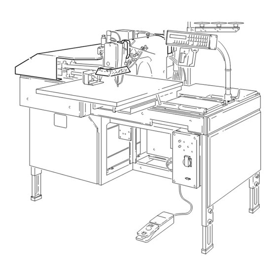
Proper use Fig. 2 - 01 The PFAFF 3574-2/02 is used for the industrial manufacture of freely programmable lockstitch seams within a seam type area of 180 x 220 mm, e.g. for decorative patterns, emblems, ornaments, decorative and assembly seams, bartack seams as well as assembly and closing seams on three-dimensional workpieces. -
Page 11: Specifications
Specifications Specifications Sewing head: ....................483 with -900/51 Sewing speed: ..................max. 2600 spm Stitch length: ..................... max. 6 mm Stitch type: ....................301 (lockstitch) Needle system: ......................134-35 Needle size: ..................... 80 - 120 Nm Clearance under presser foot: .................. 10 mm Sewable material thickness: ................ -
Page 12: Disposal Of The Machine
Disposal of the machine Disposal of the machine The proper disposal of the machine is the responsibility of the customer. The materials used are steel, aluminium, brass and various plastics. The electrical equipment consists of plastics and copper. The machine must be disposed of in accordance with applicable local environmental protection regulations. -
Page 13: Transport Packaging And Storage
Transport, packaging and storage Transport, packaging and storage Transport to the customer’s premises Within Germany, the machine is delivered without packaging. Machines for export are packaged. Transport within the customer’s premises The manufacturer bears no liability for transport within the customer’s premises or to the individual locations of use. -
Page 14: Explanation Of The Symbols
Explanation of the symbols Explanation of the symbols In this Instruction Manual, tasks to be carried out and important information are drawn to your attention by symbols. The symbols have the following meanings: Note, information Cleaning, care Lubrication Servicing, repairing, adjustment, maintenance (only to be carried out by specialist personnel) 6 - 1... -
Page 15: Controls
Controls Controls On/off switch By turning main switch 1, the machine is switched on or off. Fig. 7 - 01 Foot switch When the foot switch 1 is actuated, the following functions are called: Level 1: retain sewing jig Level 2: start sewing program Fig. -
Page 16: Control Panel
Controls Control panel The control panel consists of the display and two key panels. Fig. 7 - 03 Display .03.01 The display is divided into 2 lines: In the top line, the current values appear beneath the corresponding symbols. Program number (from 0 - 99) Stitch length (in mm) Nominal speed (in min Actual speed (in min... -
Page 17: Control Panel Operation Modes
Controls Control panel operation modes .03.02 You can select the operation modes by pressing the following keys. The selected mode can be seen by the light emitting diode in the respective key. SEWING mode INPUT mode Within both of the operation modes, only certain keys are assigned functions (see chapter 7.03.03 Functions in the SEWING mode and chapter 7.03.04 Functions in the INPUT mode). -
Page 18: Functions In The Input Mode
Controls Functions in the INPUT mode .03.04 The following functions can be selected by pressing the corresponding green key. Program station A When the function is activated (diode lit), a previously stored program is called. Program station B When the function is activated (diode lit), a previously stored program is called. Program selection When the function is activated (diode lit), a previously stored program can be selected via the number keys or the plus/minus keys. -
Page 19: Mounting And Commissioning The Machine
Mounting and commissioning the machine After unpacking the machine, check it for any transport damage. In case of damage, inform the shipping company and the responsible PFAFF dealer. The machine must only be mounted and commissioned by qualified personnel! All relevant safety regulations are to be observed! Mounting The location where the machine is set up must have a flat, sturdy surface. -
Page 20: Connecting The Foot Switch
Mounting and commissioning the machine Connecting the foot switch .01.02 Connect plug 1 in the socket and secure with the circlip. Fig. 8 - 02 Connecting disk drive and/or programming panel .01.03 For disk drive and/or programming panel, connect the transmission cable plug to socket 1. -
Page 21: Mounting The Reel Stand
Mounting and commissioning the machine Mounting the reel stand .01.04 Mount the reel stand according to Fig. 8-04. Then insert the reel stand in the frame and secure with the enclosed nuts. Fig. 8 - 04 Commissioning the machine When the machine is commissioned, the zero point of the jig control must be checked and adjusted, if required. -
Page 22: Checking/Setting Zero Point
Mounting and commissioning the machine Checking/setting zero point It is necessary to check/set the zero point when the machine is commissioned and following a cold start. Fig. 8 - 05 Call INPUT mode. Select the SERVICE function via the number key 7. Select the SET ZERO POINT function via the number key 7. -
Page 23: Preparation
Preparation Preparation All regulations and instructions in this Instruction Manual are to be observed! Special attention is to be paid to the safety regulations! All preparation work is only to be carried out by appropriately trained personnel. Inserting the needle Turn off the machine! Danger of injury if machine is switched on suddenly! -
Page 24: Winding The Bobbin Thread, Adjusting The Bobbin Thread Tension
Preparation Winding the bobbin thread, adjusting the bobbin thread tension Fig. 9 - 02 Place an empty bobbin 1 onto bobbin winder spindle 2. Thread the bobbin in accordance with Fig. 9-02 and wind it counter-clockwise around bobbin 1 a few times. Switch on the bobbin winder pressing bobbin winder spindle 2 and lever 3. -
Page 25: Inserting/Removing The Bobbin Case
Preparation Inserting/removing the bobbin case Turn off the machine! Danger of injury if the machine is switched on suddenly! Removing the bobbin case: Open latch 1 and remove bobbin case 2. Inserting the bobbin case: Press the bobbin case 2 until you feel it engage in the bobbin. -
Page 26: Threading The Needle Thread / Adjusting The Needle Thread Tension
Preparation Threading the needle thread / Adjusting the needle thread tension Fig. 9 - 05 Turn the machine off! Danger of injury if machine is switched on suddenly! Thread the machine as shown in Fig. 9-05. Adjust the needle thread tension by turning knurled screws 1 and 2. 9 - 4... -
Page 27: Selecting The Program Number
Preparation Selecting the program number Sewing programs already entered are called as described below. Fig. 9 - 06 Select INPUT mode. Press program selection key. Select program station in which the desired program is to be stored. (The diode in the key of the selected program station lights up.) Enter the number of the desired program via the number keys. -
Page 28: Inserting Sewing Jig
Preparation Inserting sewing jig Fig. 9 - 07 The sewing jig must correspond to the pre-selected sewing program! Otherwise, the wrong combination of sewing jig and sewing program can cause serious damage to the machine and the sewing jig. Insert workpiece in the sewing jig. Insert the sewing jig in bracket 1. -
Page 29: Sewing
Sewing Sewing Fig. 10 - 01 Switch on machine at main switch 1. Move feed carriage 2 manually to zero point (in direction of arrow until it stops). Press the home position key on the control panel. (Feed carriage moves to home position.) Confirm zero point via the Enter key or reset (see chapter 8.04 Checking/setting zero point). -
Page 30: Programming
Programming Programming Summary of the functions in INPUT mode In the INPUT mode, a distinction is made between direct functions and menu functions. Direct functions .01.01 Direct functions are used often and can be selected directly via the corresponding keys. Program station A Program station B Program selection... -
Page 31: Summary Of The Menu Functions
Programming Summary of the menu functions .01.03 Home position INPUT 1 - MEMORY DIRECTORY 1 - PROGRAM DIRECTORY 1 - PROGRAM MANAGEMENT 2 - DISC DIRECTORY 2 - READ PROGRAM FROM DISC 1 - READ ONE PROGRAM (DISC) 2 - READ ALL PROGRAMS (DISC) 3 - DELETE PROGRAM 1 - DELETE ONE PROG. -
Page 32: Examples For Selecting Functions
Programming Examples for selecting functions Selecting a direct function .02.01 To change the stitch length, for example, proceed as follows: Select INPUT mode. Display: "CHOOSE FUNCTION OR SCROLL # 200" Press stitch length change key. e.g. Display: "PROGRAM:1 STITCHL.3.20 # 211" Via the number keys, enter the number of the program to be changed (e.g. -
Page 33: Explanation Of The Menu Functions
Programming Explanation of the menu functions The functions are divided into main functions (1st menu level) and subfunctions (2nd and 3rd menu levels). 1- PROGRAM MANAGEMENT All of the subfunctions are listed under this main function which have to do with the organization of sewing programs. - Page 34 Programming 6- FORMAT DISC (DELETE) Discs can be reformatted (720 KB). If the disc is reformatted, all of the data on the disc are deleted. 7- DATA TRANSFER WITH PC Via this function, the control is made ready to transmit in order to communicate directly with a PC via the SYS 3000 software.
- Page 35 Programming 7- CARRIAGE START (NIS = needle in material) Needle at TDC Needle pierces material, Needle leaves carriage stops, the material, command for carriage carriage start start is output approx. at 270° approx. at 90° Needle in material, continuous area of 180°...
- Page 36 Programming 3- LANGUAGES Several languages are listed here from which the desired user language can be selected. 1- GERMAN 2- ENGLISH 3- FRENCH 4- SPANISH 5- ITALIAN 4- OTHER FUNCTIONS Under this subfunction are other subfunctions which can be turned on or off with the number keys 1 or 0.
- Page 37 Programming 2- STEPPING MOTOR X-AXIS The clearance under the needle must not blocked! Via the plus/minus keys, the motor can be moved forward or backward. 3- STEPPING MOTOR Y-AXIS The clearance under the needle must not blocked! Via the plus/minus keys, the motor can be moved forward or backward. 4- THREAD TRIMMING SEQUENCE The clearance under the needle must not blocked! By pressing the Enter key, a thread trimming sequence is carried out.
-
Page 38: Programming Panel
Programming Programming panel The programming panel comprises a display and a key field for entering/correcting sewing programs. User interface / menu mode / error messages Coordination of x- or y-axis in 1/10 mm Text number Section number Section type 1 : PROGRAM NUMBER # 901 PROGRAM NUMBER : 1 # 601... -
Page 39: Direct Functions
Programming Direct functions .04.02 Via these keys, the selected function is carried out directly. Seam pattern forwards Carry out seam pattern forwards step by step. Seam pattern backwards Carry out seam pattern backwards step by step. Presser foot up/down The presser foot is raised/lowered and at the same time, the feeding clamp of the sewing jig is opened or closed. -
Page 40: Functions For Block And Pattern Manipulation
Programming Functions for block and pattern manipulation .04.04 Block (not available yet) Move pattern An entire seam pattern can be moved with this function. Example: Supporting point 2 is moved to 2'. Beginning at supporting point 2', all of the coordinates are then changed proportionately. - Page 41 Programming Stitch width Superimposes a zigzag stitch on a basic line. Circle Input of a circular seam. Circular arc Input of a seam with the shape of a circular arc. Curve end Transformation of a curve supporting point to a curve end point. Quick motion Start sewing Trim thread...
-
Page 42: Seam Pattern Programming
Programming Seam pattern programming .04.06 The following description deals with entering a sewing program via the programming panel and is illustrated by an example. Ideally, a pattern or drawing with the required coordinates is to serve as the draft for the program. End point of straight line Seam start Seam 1... - Page 43 Programming 3 : OBSTACLES OBSTACLES : YES " + " , NO " - " The selection depends on the clamp type. 3 : OBSTACLES CLAMP WITHOUT OBSTACLE Following input of the above functions switch to INSERT mode. The diode in the key is lit. Activate straight line function.
- Page 44 Programming 6 : STRAIGHT LINE 1. OPEN 1ST CLAMP WITH ENTER Enter Open clamp. Activate loading position program end. 8 : LP-PROGRAM END With the functions seam pattern forwards or seam pattern backwards, the functions carried out can be checked in basic mode. Activate INSERT mode.
- Page 45 Programming Select desired standard stitch length (e.g. 2 mm). Press Enter key. Enter 11 : STANDARD STITCH LENGTH STANDARD STITCH LENGTH 2.00 MM Activate straight line function. 11 : STANDARD STITCH LENGTH INSERT STRAIGHT LINE Carry out seam 1 to the end point of the straight line (see Fig. 11-03). ENTER STRAIGHT LINE END POINT Press Enter key.
- Page 46 Programming 14 : STRAIGHT LINE STRAIGHT LINE END POINT Select thread trimming function. 15 : TRIMMING Activate quick motion function. 15 : TRIMMING INSERT QUICK MOTION Move to seam start of seam 4 (see Fig. 11-03). 15 : TRIMMING ENTER END POINT QUICK MOTION Press Enter key.
- Page 47 Programming 28 : CURVE END POINT CIRCULAR ARC Press Enter key. Enter 28 : CURVE END POINT ENTER ARC SUPPORTING POINT At the circular arc starting point, an additional supporting point as well as the circular arc end point must be marked. Move to supporting point (see Fig.
- Page 48 Programming Activate start sewing function 33 : START SEWING Activate graphics menu function. Press plus/minus keys until the CIRCLE function appears in the display. CIRCLE Press Enter key. Enter ENTER CIRCLE SUPPORTING POINT 1 To create the circle, two additional supporting points must be marked. Move to first supporting point (see Fig.
-
Page 49: Correcting Sewing Program
Programming Press program end key. 32 : QUICK MOTION CREATE STITCH DATA WITH " + " Press plus key. STITCH GENERATION IN PROGRESS PROGRAMMING DISPLAY SWITCHED OFF The completed sewing program is now in the machine memory with its assigned program number. - Page 50 Programming DELETE ORIGINAL PROGRAM WITH " + " Press minus key if you want to keep the original program. If the clamps are still open, the following display appears: CLOSE CLAMPS Close the clamps with the foot switch. Carry out sewing program step by step and proceed as described in chapter 11.04.06 Seam pattern programming.
-
Page 51: Care And Maintenance
Care and maintenance Care and maintenance Clean the entire machine ..................weekly Clean the hook compartment ......daily, more often for continuous operation Check oil level ...................... annually Clean blower air filter ..................once a week Check air pressure ................... daily before use Clean air filter of filter / lubricator .............. -
Page 52: Filling The Oil Reservoir
Use only oil with a viscosity of 10.0 mm /s at 40°C and a density of 0.865 g/cm at 15°C. We recommended PFAFF sewing machine oil Part no. 280-1-120 144. Fig. 12 - 02 Cleaning the blower air filter Open the cover on the left below the power table. -
Page 53: Checking/Adjusting Air Compression
Care and maintenance Checking/adjusting air compression Pressure gauge 1 should display a pressure of 6 bar! Check air compression on pressure gauge 1 before each use. Adjust air compression if necessary by turning knob 2. Fig. 12 - 04 Cleaning the air filter of the air filter / lubricator If an air compression of 6 bar is no longer achieved, filter element 1 must be cleaned. -
Page 54: Emptying The Water Trap
Care and maintenance Emptying the water trap Make sure knurled bush 1 is unscrewed as far as possible (left thread). If the water level is rising, the automatic drain will open and the water drain off. Place a suitable collection vessel underneath the drain. -
Page 55: Adjustment
Adjustment Adjustment Notes on adjustment All the adjustments described in this manual refer to a completely installed machine and may be carried out only by appropriately trained personnel. The machine covers which must be unscrewed and replaced for checks and adjustment work are not mentioned in the text. -
Page 56: Pulling Out/Inserting The Sewing Head
Adjustment Pulling out/inserting the sewing head The sewing head must be pulled out of the unit for maintenance and adjustment work. Fig. 13 - 01 To tilt back the sewing head, push away control panel 1 (clamp lever 2). Remove plate 3 (screw 4). Loosen clamp screw 5 behind the sewing head. -
Page 57: Checking And Adjustment Aids
Adjustment Checking and adjustment aids The necessary needle bar positions can be fixed exactly by blocking holes 1 and 3-6. Fig. 13 - 02 Turn the handwheel until the needle bar is approximately in the position required. Insert the adjustment pin into the relevant hole provided and apply pressure. Turn the handwheel slightly forwards and backwards until the adjustment pin engages in the crank slot behind the bearing plate and thus blocks the machine. -
Page 58: Adjustment Of The Sewing Head
Adjustment Adjustment of the sewing head Adjusting the synchronizer .06.01 Requirement Upon completion of the sewing operation, the sewing machine should be positioned in the TDC of the needle bar. Fig. 13 - 03 Switch on the machine. Slide the feed carriage to zero point by hand (see Chapter 8.04 Checking /setting zero point). -
Page 59: Preadjusting Needle Height
Adjustment Preadjusting needle height .06.02 Requirement In the BDC of the needle bar, the distance between the bottom edge of needle bar 1 and the needle plate should be approx. 16.5 mm. Fig. 13 - 04 Position needle bar 1 in the BDC. Move needle bar 1 (screw 2), without turning it, according to the requirement. -
Page 60: Counter Presser Lifting Stroke
Adjustment Counter presser lifting stroke .06.03 Requirement With the needle bar at 0.6 past BDC (hole 3), 1. the counter presser should be in its top point of reversal and 2. the cutout of eccentric 1 should be positioned more or less vertically below the center of the axle. -
Page 61: Needle In The Needle Hole Center
Adjustment Needle in the needle hole center .06.04 Requirement The needle should penetrate right into the center of the needle hole. Fig. 13 - 06 Position the needle immediately above the needle hole. Loosen screws 1, 2 and 3 (behind screw 4). Move needle bar frame 5 according to the requirement. -
Page 62: Hook Shaft Bearing And Hook-To-Needle Clearance
Adjustment Hook shaft bearing and hook-to-needle clearance .06.05 Requirement 1. The groove in bearing 3 (see arrow) should be visible from below and there should be slight but palpable play between gear wheels 5 and 9. 2. When the hook is resting lightly on the centrifugal disk and the hook point is positioned at the center of the needle, there should be a clearance of less than 0.1 mm between the hook point and the clearance cut of the needle. -
Page 63: Needle Rise, Needle Height And Bobbin Case Position Stop
Adjustment Needle rise, needle height and bobbin case position stop .06.06 Requirement 1. With the needle bar at 1.8 past BDC (hole 4), the hook point should be positioned on the right side of the needle. 2. In the needle rise position, the top edge of the needle eye should be positioned 0.8 mm below the hook point and 3. -
Page 64: Bobbin Opener Height
Adjustment Bobbin opener height .06.07 Requirement At the left point of reversal of bobbin opener 3, the top edge of its finger should be positioned 0.5 mm above the bottom edge of trip 4. 0.5 mm Fig. 13 - 09 Turn bobbin opener bearing 1 (screw 2) according to the requirement. -
Page 65: Bobbin Opener Position
Adjustment Bobbin opener position .06.08 Requirement In the left point of reversal of bobbin opener 1, 1. the front edge of the bobbin opener finger should be positioned approx. 0.6 mm behind the front edge of trip 5 and 2. the bobbin case base should be pushed back approx. 0.3 mm from the position finger of bobbin case position stop 6 and rest against screw 4 on stop pin 7. -
Page 66: Bobbin Opener Movement
Adjustment Bobbin opener movement .06.09 Requirement With the needle bar at 1.8 past BDC (hole 4), bobbin opener 3 should be positioned in its right point of reversal. Fig. 13 - 11 Adjust eccentric 1 (screw 2) according to the requirement. To provide a better indication of the movement of the bobbin opener, a screwdriver can be inserted in the jam slot of bobbin opener 3. -
Page 67: Thread Check Spring And Slack Thread Regulator
Adjustment Thread check spring and slack thread regulator .06.10 Requirement 1. The stroke of thread check spring 3 should be completed when the needle point penetrates the material (spring stroke approx. 7 mm). 2. Slack thread regulator 4 should be so secure in its elongated hole that thread check spring 3 moves approx. -
Page 68: Thread Puller
Adjustment Thread puller .06.11 Requirement Upon completion of a sewing operation, thread puller 3 should pull enough thread to ensure a secure beginning of seam and without breaking the thread. Fig. 13 - 13 Adjust restrictors 1 and 2 according to the requirement. The time for the thread puller can be adjusted via the control panel using the function "TIME FOR THREAD PULLER"... -
Page 69: Bobbin Winder
Adjustment Bobbin winder 06.12 Requirement 1. When the winder is switched on, the bobbin winder spindle should move securely with the winder. 2. When the winder is switched off, friction wheel 5 must not engage drive wheel 1. 3. The bobbin winder should switch off automatically when the bobbin has been filled to approx. -
Page 70: Presser Foot Lifting Movement
Adjustment Presser foot lifting movement .06.13 Requirement With the needle bar at TDC (hole 5), the presser foot should be in its top point of reversal. Fig. 13 - 15 Position the take-up lever in its top position and loosen screw 1. Position the needle bar at TDC and turn eccentric 2 according to the requirement. -
Page 71: Presser Foot Depression Time
Adjustment Presser foot depression time .06.14 Requirement The presser foot should be depressed for as long as the needle is in the workpiece. Fig. 13 - 16 Position the needle bar at BDC. Position articulated joint 1 (screws 2 and 3) so that it is centered and horizontal. 13 - 17... -
Page 72: Adjusting The Presser Bar
Adjustment Adjusting the presser bar .06.15 Requirement When presser bar 1 is raised, there should be a distance of 1 mm between bush 3 and lever 4. Fig. 13 - 17 Switch on the machine. Make sure the foot switch is not actuated! Risk of injury if the machine starts unexpectedly! Move presser bar 1 (screw 2) according to the requirement. -
Page 73: Bottom Point Of Reversal Of The Presser Foot And Lift
Adjustment Bottom point of reversal of the presser foot and lift .06.16 Requirement With screw 1 screwed in as far as possible and nut 3 unscrewed as far as the circlip, 1. presser foot 4 should rest on the needle plate (counter presser) in its bottom point of reversal. -
Page 74: Adjusting The Presser Foot To Fabric Thickness
Adjustment Adjusting the presser foot to fabric thickness .06.17 Requirement In its bottom point of reversal, the distance between the presser foot and the needle plate should be appropriate to the fabric thickness. Fig. 13 - 19 Adjustment to uniform fabric thickness: Turn nut 1 according to the requirement. -
Page 75: Thread Trimmer Adjustment
Adjustment Thread trimmer adjustment Dismantling/assembling the control unit .07.01 Fig. 13 - 20 To dismantle the control unit, pull plug 1 out of the socket of the motor guide plate or the control box. Loosen screw 2 and remove pull rod 3. Remove connecting rod 4. -
Page 76: Preadjusting The Control Cam
Adjustment Preadjusting the control cam .07.02 Requirement With the needle bar at TDC (hole 5) 1. the beginning of the highest boss of the trip of control cam 6 must be positioned below the tip of latch 8, and 2. the right side of the trip must be flush with the right side of latch 8..Fig. -
Page 77: Roller Lever
Adjustment Roller lever .07.03 Requirement With the needle bar at 1.8 past TDC (hole 4), 1. when roller lever 4 is tapped, the roller must engage easily in the control cam 7, 2. the roller of roller lever 4 must be centered at the cam recess of control cam 7. Fig. -
Page 78: Latch
Adjustment Latch .07.04 Requirement When the thread trimmer is in the resting position, there should be a distance of 0.3 mm between latch 2 and the highest boss of control cam 1. 0.3 mm Fig. 13 - 23 By turning the handwheel, position the bearing surface of control cam 1 with its largest eccentricity below latch 2. -
Page 79: Engaging Solenoid
Adjustment Engaging solenoid .07.05 Requirement With the needle bar at 1.8 past BDC (hole 4), there should be a distance of 0.2 to 0.3 mm between engaging lever 1 and latch 2 when the engaging solenoid is actuated. Fig. 13 - 24 Position the needle bar at 1.8 past BDC. -
Page 80: Actuating Lever
Adjustment Actuating lever .07.06 Requirement With the needle bar at 1.8 past BDC (hole 4) and engaging lever 1 actuated, there should be a distance of approx. 0.2 mm between the roller of roller lever 2 and the base of control cam 3. -
Page 81: Engaging Lever
Adjustment Engaging lever .07.07 Requirement With the needle bar at TDC (hole 5) and the thread trimmer in the resting position, there should be a distance of 0.3 to 0.5 mm between the roller of roller lever 3 and the outer diameter of control curve 4. -
Page 82: Lateral Alignment Of The Thread Catcher
Adjustment Lateral alignment of the thread catcher .07.08 Requirement 1. The tip of thread catcher 6 should point exactly to the center of the needle. 2. Thread catcher 6 should not brush against anything when moving. Fig. 13 - 27 Unscrew the needle plate and feed dog. -
Page 83: Front Point Of Reversal Of The Thread Catcher
Adjustment Front point of reversal of the thread catcher .07.09 Requirement In the front point of reversal of thread catcher 3, the rear edge of the thread catcher cut- out should be positioned 1 mm in front of bobbin case position stop 4. Fig. -
Page 84: Readjusting The Control Cam
Adjustment Readjusting the control cam .07.10 Requirement When the end of thread guard 1 is 2 mm behind the center of the projection of bobbin case position stop 2, there should be a distance likewise of 2 mm between the tip of thread catcher 6 and the center of the projection. -
Page 85: Catch Spring
Adjustment Catch spring .07.11 Requirement When the thread trimmer is in the resting position, there should be a distance of 0.5 mm between catch spring 1 and roller lever 3. 0.5 mm Fig. 13 - 30 Mount catch spring 1 together with the cover disk. Slightly tighten screws 2. -
Page 86: Distance Of Knife To Needle
Adjustment Distance of knife to needle .07.12 Requirement There should be a distance of 4 mm between the front edge of knife 1 and the needle. 4 mm Fig. 13 - 31 Position the needle bar at BDC. Slide knife 1 under the locking tab and align according to the requirement. Slightly tighten screw 2. -
Page 87: Manual Cutting Function Test
Adjustment Manual cutting function test .07.13 Requirement Both threads must be cut perfectly both right and left in the thread catcher cutout. Fig. 13 - 32 Position the needle bar at BDC and actuate the engaging lever by hand. Turn the handwheel until thread catcher 1 is in its front point of reversal. Take two threads double and hang them in the cutout of thread catcher 1. -
Page 88: Needle Thread Tension Release
Adjustment Needle thread tension release .07.14 Requirement 1. When the thread trimmer is in the resting position, trip 5 should be engaged and have a distance of 0.5 mm to release olive 1. 2. When trip 5 is positioned at the highest point of release olive 1, the tension disks of thread tension should be at least 0.5 mm apart. - Page 89 Notes...
- Page 90 G.M. PFAFF Aktiengesellschaft Postfach 3020 D-67653 Kaiserslautern Königstr. 154 D-67655 Kaiserslautern Telefon: (0631) 200-0 Telefax: (0631) 172 02 Telex: 45753 PFAFF D Gedruckt in der BRD Printed in Germany Imprimé en R.F.A. Impreso en la R.F.A. Stampato in R.F.G.
Need help?
Do you have a question about the 3574-2/02 and is the answer not in the manual?
Questions and answers