Table of Contents
Advertisement
Advertisement
Table of Contents

Related Manuals for Yowza Sanibel i35


Summary of Contents for Yowza Sanibel i35
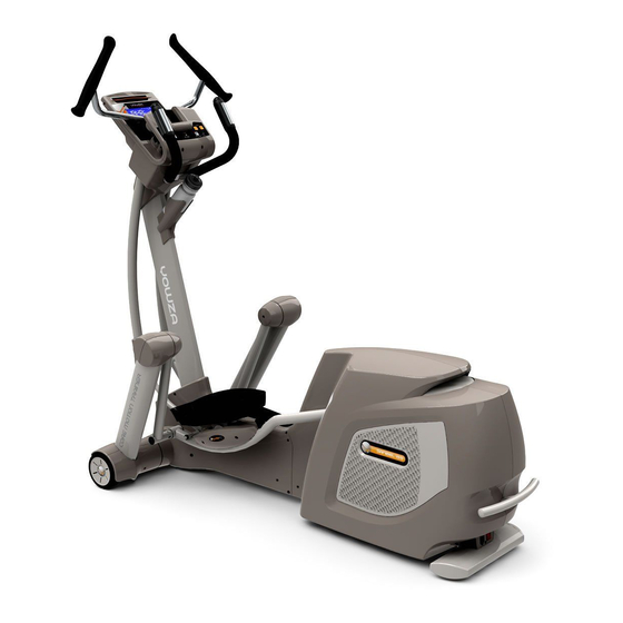
- Page 1 Express Assembly Guide Use this Guide for the following Yowza Models: Sanibel i35...
- Page 2 1.1 Place the unit in the room where you will exercise. Cut the straps and bottom of the carton all the way around. 1.2 Lift carton from the pallet and discard plastic wrap. Remove all components from the interior of the box. **IMPORTANT: Handle hardware pack carefully to avoid the dislocation of screws and bolts inside the pack.
- Page 3 2.1 Attach Incline Frame Lower Covers (341, 342) to the Incline Frame. Carefully snap pieces together using plastic guides, then secure with Cone Point Screw (408). TIP: Using a magnetic screwdriver will be beneficial when inserting all screws during assembly.
- Page 4 3.1 Remove the Undercarriage Covers (704, 705) from the main frame by lifting the pedal assembly. Carefully handle covers to avoid snapping the plastic push pins (403). Make sure the Rear Incline Frame Holders (206) are securely fastened to Main Frame.
- Page 5 4.1 Attach Incline Frame Assembly (A3) to the main frame. Secure Incline Frame Holder-Front (708) to Incline Frame using Allen Head Bolts (511) and Washers (517). Do not fully tighten Bolts (511) until step 4.2. 4.2 Align bolt hole of Incline Frame with Transmission Tube Front (110) and secure using Allen Head Bolt (507) and Nylon Nut (508).
- Page 6 5.1 Attach Console Support Tube Assembly (A2) to the Main Frame using M8x20mm Allen Head Bolts (504). Connect 8- Pin Power Wire-Upper (601) to Power Wire-Lower (602).
- Page 7 6.1 Attach the Undercarriage Covers (704, 705) to the Main Frame by lifting pedal arm and securing with Flat Point Screw (506), Screw (509) and Screw (510). 6.2 Attach Incline Frame Front Cover (703) to Incline Frame using two Screws (520).
- Page 8 7.1 Slide Bolt (505) through Washer (494), Wave Washer (521), Pedal Arm and thread into Pedal Swing Arm (108) securing with 8mm Allen Key. 7.2 Insert Back Out Screw (516) into Pedal Swing Arm (108) using the 2.5mm Allen Key – Fully Tighten. 7.3 Press the Pedal Arm Pivot Cover (702) into the ends of the Pedal Arm.
- Page 9 8.1 Connect Action Arms (118, 119) to the Moving Linkages (104, 105), secure using Bolt and Nut (502, 503) using 6mm Allen Key. **Do not over-tighten these bolts, over- tightening will result in friction related sounds. Put the Action Handlebar Lower Covers on (701) to the Action Arm and secure using Cone Point Screw (501).
- Page 10 9.1 Install the moving handlebars and tighten Allen Head Bolts (514) to lock the handlebars in place using the 5mm Allen Key.
- Page 11 10.1 Connect Button Board connection Wire (631) and make sure to insert correctly. **Make sure wires do not get between handlebar gears. 10.2 Attach Button Control Panel (A1) and secure with screw (510). Use Screw (512) on Button Control Panel’s left and right side.
- Page 12 11.1 Attach the Water Bottle Holder (709) and secure using Cone Point Screw (501) and Washer (518). YOUR CROSSTRAINER IS NOW ASSEMBLED...
Need help?
Do you have a question about the Sanibel i35 and is the answer not in the manual?
Questions and answers