
Subscribe to Our Youtube Channel
Related Manuals for Extech Instruments 382065


Summary of Contents for Extech Instruments 382065
- Page 1 User's Manual Datalogging AC/DC Power Clamp-on Meter Model 382065/382068...
-
Page 2: Table Of Contents
Hz. The frequency of Voltage and Current measurements can be displayed also. Datalogger and RS-232 PC interface features are built into the meter. The Datalogger/Data Acquisition Software package is for exclusive use with the Model 382065/382068 Clamp on Power Datalogger. Windows® 95, 98, NT, 2000, ME and XP operating systems are supported. -
Page 3: Specifications
www.burntec.com Specifications General Specifications Main display 4-digit (10,000 count) multi-function LCD Bargraph display 40-segment bargraph Datalogger 4000 data point continuous logging (25 point manual logging) with MIN / MAX and Peak detect recording Peak hold Built-in detector captures positive and negative peaks to .1ms Maximum voltage 600Vrms between any terminal and earth ground Meter power... - Page 4 www.burntec.com Overload Range Resolution Accuracy Frequency range protection 2 to 1000A 0.1A ±(1.5% + 5) 45Hz to 500Hz 1100A Crest factor < 3 for stated accuracy Overload Range Resolution Accuracy Input impedance protection 2 to 600V 0.1V ±(0.5% + 5) 1MΩ...
-
Page 5: Safety Information
www.burntec.com Safety Information 1. Read the following safety information carefully before attempting to operate or service the meter. 2. Read all operating instructions before use. 3. To avoid damage to the instrument do not exceed the published input limits. 4. Do not use the meter or test leads if they appear damaged. Use extreme caution when working around bare conductors or bus bars. -
Page 6: Meter And Display Descriptions
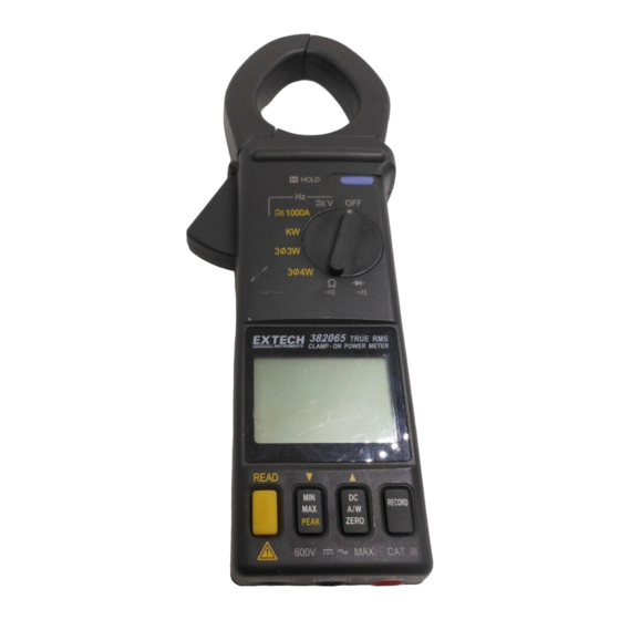
www.burntec.com Meter Description Transformer jaws LCD display Jaw trigger 10. RS-232 PC Interface Jack Data Hold button 11. COM terminal Function selector 12. VΩHz terminal Peak Detector READ button 13. Low battery indication MIN/MAX/PEAK function button 14. Analog Display DC A/W ZERO button 15. -
Page 7: Ac/Dc Power Measurements
www.burntec.com AC/DC Power Measurements AC/DC 1φ2W Power (W) and Power Factor (PF) Measurements HOLD 1000A 3 3W 3 4W 600V MAX CAT 600V Figure 3 WARNING Do not clamp on to a conductor when zeroing the jaw's residual magnetic field until the LCD reads zero. 1. - Page 8 www.burntec.com Note: When calculating KVAR, the KVAR accuracy greatly depends on V, A and KW measurement accuracy (especially when PF is very close to 1). To get a more accurate value when PF is greater than 0.91 ( φ < 25 ° ), use the following equation for a pure sine wave PF = KVA (Apparent Power): KVA = 1000...
- Page 9 www.burntec.com A. With the Clamp jaws empty , turn the meter on by setting the rotary switch to the 3 φ 3W position. WL12 will appear on the upper left side of the LCD prompting the user to take a measurement.
- Page 10 www.burntec.com HOLD 1000A 3 3W WL 23 3 4W 3 3W WL 23 3 3W WL 23 3 3W 600V 600V MAX CAT Figure 5 WL123 HOLD 3 3W Figure 6 600V MAX CAT Model 382068 V3.0 4/2005...
- Page 11 www.burntec.com 3φ4W AC/DC Power Measurement HOLD 1000A 3 3W 3 4W 3 4W 3 4W 3 4W 600V 600V MAX CAT Figure 7 HOLD 1000A 3 3W 3 4W WL 2 3 4W WL 2 WL 2 3 4W 3 4W 600V 600V Figure 8...
- Page 12 www.burntec.com HOLD 1000A WL 3 3 3W 3 4W WL 3 3 4W 3 4W WL 3 3 4W 600V 600V Figure 9 WL123 HOLD 3 4W 600V MAX CAT Figure 10 Model 382068 V3.0 4/2005...
- Page 13 www.burntec.com A. Measure W (refer to figure 6). R (L1) FR (L1) 1. With the jaw enclosure empty, turn the meter on by setting the rotary switch to the 3 φ 4W position. 2. Insert the test leads into the input terminals (black lead to the COM terminal and red to '+'). 3.
- Page 14 www.burntec.com 1φ3W Power Measurement HOLD 1000A 3 3W 3 4W WL12 3 3W WL12 3 3W WL12 3 3W 600V 600V Figure 11 HOLD 1000A WL 23 3 3W WL 23 3 3W 3 4W 3 3W WL 23 3 3W 600V 600V MAX CAT...
- Page 15 www.burntec.com 1 φ 3W power measurements are similar to 3 φ 3W unbalanced power measurement except for the nomenclature. Two measurements are required: and W WL123 HOLD RS (L1G) TS (L2G) 3 3W A. Measure W (refer to figure 11). RS (L1G) 1.
-
Page 16: Ac/Dc Voltage Measurements
www.burntec.com Current and Voltage Measurements AC, DC, and AC+DC Voltage Measurements HOLD 1000A 3 3W 3 4W 600V Figure 14 Warning: The maximum input is 600V. Do not attempt to take voltage measurements that exceed this limit; electrical shock and damage to the clamp meter can result. 1. -
Page 17: Ac/Dc Current Measurements
www.burntec.com AC, DC, and AC+DC Current Measurements HOLD 1000A 3 3W 3 4W 600V 600V Figure 15 Set the rotary switch to the '1000A' position (refer to figure 15). For DC, press and hold the ZERO button until a beep is heard to zero the reading; the LCD will display “- - - -”... -
Page 18: Resistance And Continuity Measurements
www.burntec.com Resistance and Continuity Measurements Warning: Before taking any in-circuit resistance measurements, remove power from the circuit under test and discharge all capacitors. Set the function switch to the Ω position for both resistance and continuity measurements. Connect the black test lead to the COM terminal and the red test lead to the '+' terminal. -
Page 19: Diode Tests
www.burntec.com Diode and Continuity Measurements Connect red test lead to the " + " terminal and black test lead to the "COM" terminal. 2. Set the range switch to the diode test position " ". 3. Connect the red test lead to the anode side and black test lead to the cathode side of the diode being tested. -
Page 20: Datalogging
www.burntec.com Datalogging Single mode 1. Single mode datalogging records one reading at a time. 2. To record one reading, press the RECORD key until one beep heard. (Note that if the button is held longer, 2 beeps will sound and the meter will be in continuous mode; see below). -
Page 21: Connecting The Meter To A Pc
Connecting the meter to a PC The Model 382065 includes an attachment that affixes to the bottom of the meter via its banana jacks. The PC interface cable is hardwired to this attachment. Connect the other end (DB-9) of the cable to an available PC com port. - Page 22 www.burntec.com Memory Window 1. REMAIN – Meter’s available memory. 2. ID Code – User selectable reference number. Type number in the yellow field below the ID CODE button then press the ID CODE button to confirm. 3. MEMORY – Total meter memory (amount of memory available when no readings are stored in the logger).
- Page 23 www.burntec.com Transfer (Download) remotely recorded readings to a PC 1. Connect the meter to the PC, open the software program, and turn the meter on. 2. Open the Memory window by clicking on the MEMORY button in the Main Software window.
-
Page 24: Wiring And Protocol
www.burntec.com Wiring and Protocol Wiring In order to ignore hardware handshake, the wiring should be configured as shown in the diagram below (left). The RTS must be pulled low (-10V to -12V). Note: In QBASIC, add RS in the OPEN statement. The diagram at right is the DB-9 connector schematic. PIN 2 RX PIN 3 TX PIN 4 DTR... - Page 25 www.burntec.com Byte 1 This byte is fixed. If its value is not 02, the interface is compromised or the meter is defective. Byte 2 The 7 bits in Byte 2 represent the meter’s selected mode of operation (its function). Bit 7 Bit 6 Bit 5 Bit 4...
-
Page 26: Maintenance
Periodically wipe the case with a dry cloth; do not use abrasives or solvents. Warranty EXTECH INSTRUMENTS CORPORATION warrants this instrument to be free of defects in parts and workmanship for one year from date of shipment (a six month limited warranty applies to sensors and cables).
Need help?
Do you have a question about the 382065 and is the answer not in the manual?
Questions and answers