Table of Contents
Advertisement
Quick Links
Instruction Manual
MODEL 382860
True RMS Power MultiMeter
1. INTRODUCTION
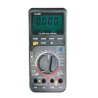
Congratulations on your purchase of the Extech Model 382860 True RMS Power MultiMeter.
Four LCD displays offer four simultaneous readings e.g. during "POWER" measurements,
simultaneous displays of power, current, AC voltage and power factor can be viewed; AUTO
RANGE always selects the correct measuring range to achieve best accuracy; REL
(Relative) function allows the operator to measure a value with respect to a preset reference
value; CMP (Comparator) function allows a comparative measurement to be made (the
upper/lower limits can be defined); MEM (Memory) and RCL (Recall) functions permit 10
measurements to be stored in memory for later recall; AUTO-POWER-OFF extends the life of
the battery by turning off the meter if neither the rotary function switch nor any button is
operated for 12 minutes. The AC Adaptor required for Power measurements is included.
1
382860
Ver. 1.5
2/01
Advertisement
Table of Contents

Related Manuals for Extech Instruments 382860


Summary of Contents for Extech Instruments 382860
-
Page 1: Instruction Manual
True RMS Power MultiMeter 1. INTRODUCTION Congratulations on your purchase of the Extech Model 382860 True RMS Power MultiMeter. Four LCD displays offer four simultaneous readings e.g. during “POWER” measurements, simultaneous displays of power, current, AC voltage and power factor can be viewed; AUTO RANGE always selects the correct measuring range to achieve best accuracy;... -
Page 2: Specifications
AC Voltage 400 mV ± (0.8%+3dgts) ± (2.5%+5dgts) 0.1mV 40 V 10mV 400 V(<200V) 100mV 400V(<400V) ± (1.0%+3dgts) 100mV 750 V AC Current ± (1.5%+3dgts) ± (2.5%+5dgts) µ µ µ 40mA µ 400mA µ ± (2.0%+5dgts) 10mA 382860 Ver. 1.5 2/01... - Page 3 Logic Test : max. 39.99 VDC overload protection 250 VDC/VAC rms Attention: Transistor, capacitance and temperature measurements are not overload protected. Exceeding the max. input limits can be hazardous to the user and can damage the meter. 382860 Ver. 1.5 2/01...
-
Page 4: Meter Description
• Do not use the meter in areas with adverse environmental conditions or where flammable gas, steam or dust may exist. For your own safety, avoid getting the meter and test leads damp or wet. 382860 Ver. 1.5 2/01... -
Page 5: Safety Symbols
This symbol adjacent to one or more terminals identifies them as being associated with ranges that may, in normal use, be subjected to particularly hazardous voltages. For maximum safety, thermometer and its test leads should not be handled when these terminals are energized. 382860 Ver. 1.5 2/01... -
Page 6: Basic Meter Operation
(see Section 8). • 20A Input Terminal For DC/AC current measurements to 20A max, insert the Red test-lead to this input socket. Attention: During current measurements the rotary switch must not be set to voltage positions. 382860 Ver. 1.5 2/01... - Page 7 (actual) measurement displays on the Main LCD. The left sub-display will show the difference in % and the right sub- display will continue to show the preset reference value. 382860 Ver. 1.5 2/01...
- Page 8 AUTO-POWER-OFF extends the life of the battery: if neither the rotary function switch nor any button is operated for 12 minutes the DMM is automatically turned off. During active “communication” of the multimeter with a PC, AUTO-POWER- OFF is disabled. 382860 Ver. 1.5 2/01...
-
Page 9: Measurement Instructions
Attention: Make sure all objects, circuits and components under test are NOT powered! Set the rotary switch to the Ohms position. Press the AC/DC key so that the continuity musical symbol does NOT appear on the LCD. 382860 Ver. 1.5 2/01... - Page 10 For the best accuracy, the use of BNC-Cables is strongly recommended. During frequency measurements, the right sub-display shows the dB-value of the AC voltage, the middle sub-display shows the AC voltage “V” and the main display: the present input value (frequency). 382860 Ver. 1.5 2/01...
-
Page 11: Transistor Test
6.10 Logic Test This function allows logic level tests in digital circuits. Switch the meter power ON. Set the rotary switch to the “LOGIC” position. The LCD displays “rdy” (ready). Connect the test-leads as follows: COM-input socket (black lead); V-Ohm socket (red lead). 382860 Ver. 1.5 2/01... -
Page 12: Power Measurements
2. The digit to the upper left of the left-most sub-LCD indicates the present mode. Refer to the Table below for an overview of the display modes for the Main LCD and the three Sub-LCDs. Then refer to the explanations below for accumulated watts, cost, etc. 382860 Ver. 1.5 2/01... - Page 13 To save (store) the cost per hour, KW/H, and accumulated cost data, press the FUNCTION key or turn the Rotary Switch to another range AFTER DISCONNECTING THE POWER ADAPTOR. Never change the Rotary 382860 Ver. 1.5 2/01...
- Page 14 Copy the files from the GRAPHIC sub-directory on the supplied program floppy disk to your hard disk. For example, type: copy a:\GRAPHIC c: To run the program, type METEX (ENTER) Follow the on-screen help for specific operating instructions. 382860 Ver. 1.5 2/01...
-
Page 15: Maintenance
Remover power to the meter and disconnect any cables or test leads. Open the battery compartment by removing the rear battery compartment screw with a Phillips screwdriver. Exchange battery and reinstall the battery compartment cover. Tech Support Hotlines 781-890-7440 ext. 200 extech@extech.com www.extech.com 382860 Ver. 1.5 2/01... -
Page 16: Repair And Calibration Services
12. WARRANTY EXTECH INSTRUMENTS CORPORATION warrants the basic instrument to be free of defects in parts and workmanship for one year from date of shipment (a six month limited warranty applies on sensors and cables). If it should become necessary to return the instrument for service during or beyond the warranty period, contact the Customer Service Department at (781) 890-7440 for authorization.
Need help?
Do you have a question about the 382860 and is the answer not in the manual?
Questions and answers
Extech multimeter model 382860 I need set of new test leads for this meter need price on all leads for this unit