
Related Manuals for Extech Instruments 381676A


Summary of Contents for Extech Instruments 381676A
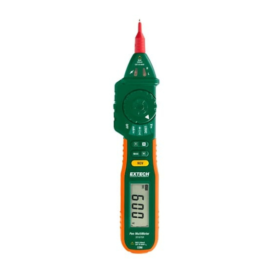
- Page 1 USER GUIDE Pen Multimeter with Voltage Detector Model 381676A GlobalTestSupply www. .com nd Quality Products Online at: sales@GlobalTestSupply.co...
- Page 2 Never touch probes, test leads, or alligator clip when connected to live circuit. Do not measure voltage on terminals that exceed 600V above earth ground. Always use caution when working with voltages above 60VDC or 30VACrms. Keep fingers behind probe barrier when taking measurements. Never connect test leads across a voltage source while the rotary switch is in the resistance, continuity, or diode mode of operation. Never perform resistance, continuity, or diode tests on live circuits. When taking non‐contact voltage measurements ensure that the positive test lead is NOT exposed and that the negative (common) test lead is not connected to the bottom of the meter. Before changing functions using the rotary function dial, be sure to disconnect the meter’s test leads from any circuit under test. Never use the meter in an explosive environment or where dust, dirt, or steam exists. Never use the meter if the housing or battery compartment is open. Do not store meter in direct sunlight, high temperature/humidity, or condensation. If the equipment is used in a manner not specified by the manufacturer, the protection provided by the equipment may be impaired. ALWAYS discharge filter capacitors in power supplies and disconnect the power when making resistance or diode tests. 381676A-en-GB_V1.1 08/15 GlobalTestSupply www. .com nd Quality Products Online at: sales@GlobalTestSupply.co...
- Page 3 Ohms Low battery D.H Data Hold ‐12 µ micro (10 ) A Amperes ‐3 m milli (10 ) (volts) DC Direct current k kilo (10 ) ohms AC Alternating current M Meg (10 ) ohms M.H Maximum Hold 381676A-en-GB_V1.1 08/15 GlobalTestSupply www. .com nd Quality Products Online at: sales@GlobalTestSupply.co...
- Page 4 M (Mode) Switch between AC and DC V, A, , Voltage/Current. Hold down to do Logic level testing. Switch between resistance, diode, and continuity Button Details DATA HOLD (H) Button To freeze a displayed reading, press the DATA HOLD (H) button. The reading will freeze and the D.H display icon will be visible on the LCD. To release the display, press the DATA HOLD (H) button again. The D.H indicator will switch off and the display will again show real time readings. MAXIMUM HOLD (MAX) Button To display only the highest reading, press the MAX button. The M.H display icon will be visible on the display while in the Max Hold mode. Now, the display will only change when a higher reading than the displayed reading is encountered. To return to normal operation, press the MAX button again (the M.H display icon will switch off). MODE (M) BUTTON The Mode (M) button is used to select AC or DC while in the VOLTAGE (V) or CURRENT (mA) modes. The Mode (M) button is used to select diode ( ), Continuity ( ), or Resistance (). Press and hold the Mode (M) button to take LOGIC tests while in the LOGIC mode. RANGE (R) Button The meter automatically selects the optimum range; however, the meter’s ranges can be selected manually. When using the Range (R) button to manually select a range, start with the highest range and then select successively lower ranges until the desired range is reached. The decimal place will move with each press of the RANGE button. Press and hold the Range (R) button to return to the AUTO Range mode. 381676A-en-GB_V1.1 08/15 GlobalTestSupply www. .com nd Quality Products Online at: sales@GlobalTestSupply.co...
- Page 5 Test Lead Notes The supplied black test leads (standard test lead and alligator clip probe) have protective plugs that must be removed before being inserted in the bottom of the meter. This protective apparatus must be removed from the end of the lead that plugs into the meter. The positive (+) red probe cover is used when making Category III or higher measurements. Twist to remove this probe cover when making Category II or lower measurements. Maximum Input Limits Measurements Input Limits Voltage DC or AC 200mV range: 250V DC or AC rms 2~600V range: 600V DC or AC rms Current DC or AC Fuse protection (FF400mA/600V) Logic, Resistance, Continuity, and Diode 250V DC or AC rms Automatic Power OFF (APO) The meter is equipped with an automatic power off feature to preserve battery energy. After 14 minutes of inactivity the meter will emit 5 short beeps. After another minute the meter will emit one long beep before finally turning off. To turn the meter on again, simply rotate the function switch to the desired function. To defeat the APO feature, press and hold the H button while turning the meter on. The APO feature will re‐enable after the meter is turned off again. 381676A-en-GB_V1.1 08/15 GlobalTestSupply www. .com nd Quality Products Online at: sales@GlobalTestSupply.co...
- Page 6 NON‐CONTACT AC VOLTAGE DETECTOR (NCV) WARNING: Test the AC voltage detector on a known live circuit before each use. WARNING: Before using the meter in the AC Voltage Detector mode, verify that the batteries are fresh by confirming characters appear on the LCD when the function dial is turned to the voltage (V) position. Do not attempt to use the meter as an AC Voltage Detector if the batteries are weak or bad. Notes: Voltage may still exist even with no indication given by the meter. Do not solely rely on NCV detection to determine the presence of voltage. Socket design, insulation thickness and other factors may affect readings. The NCV indicator LED may flash while measuring AC/DC voltage due to the presence of induced voltage. External environmental interference from additional sources can falsely trigger NCV detection. 1. Disconnect the common (negative) test lead from the bottom of the meter. 2. With the function switch set to any position except OFF, press and hold the NCV button. 3. Move the tip of the meter near the voltage source or conductor as shown. 4. If the voltage detected is > 110VAC, the beeper will sound and the NCV indicator near the tip of the meter will flash. Always test the detector on a known live circuit first before attempting other tests. 381676A-en-GB_V1.1 08/15 GlobalTestSupply www. .com nd Quality Products Online at: sales@GlobalTestSupply.co...
- Page 7 ‘OL’ indicates an over‐range condition in manual mode. A higher range should then be selected. In manual mode, select the highest range first if the value to be measured is unknown then lower the range as needed. The AC millivolt range is only available in the manual range mode. 1. Use the probe cover if making measurements on category III or above installations. 2. Set the function dial to the V position. 3. Use the Mode (M) button to select AC or DC. 4. Insert the black test lead banana plug into the negative jack at the bottom of the meter. 5. Touch the black test probe tip to the neutral side of the circuit for AC measurements or to the positive side of the circuit for DC measurements. 6. Touch the positive test probe tip to the “hot” side of circuit for AC measurements or to the negative side of the circuit for DC measurements. 7. Read the voltage on the display. The meter automatically selects optimum range or the user may manually select a range by pressing the Range (R) button. Press and hold the Range (R) button to return to the AUTO Range mode. 381676A-en-GB_V1.1 08/15 GlobalTestSupply www. .com nd Quality Products Online at: sales@GlobalTestSupply.co...
- Page 8 Touch the positive test probe tip to the positive side of the circuit. Read the current reading on the display. The meter automatically selects the optimum range or the user may manually select a range by pressing the Range (R) button. Press and hold the Range (R) button to return to the AUTO Range mode. DIODE TEST NOTES: The display shows the approximate forward voltage drop. If the connections are reversed or the leads are not connected, the display will show ‘OL’. Use the probe cover if making measurements on category III or above installations Set the function switch to the position. Use the Mode (M) button to select the diode function Insert the black test lead banana plug into the negative (common) jack at the bottom of the meter. Touch the test probes to the diode under test. A good diode will indicate approx. 0.3V (germanium diodes) to 0.7V (silicon diodes) for the forward test and “OL” for the reverse test. A shorted diode will indicate the same value of voltage in both the reverse and forward test directions. An open diode will indicate “OL” in both test directions. 381676A-en-GB_V1.1 08/15 GlobalTestSupply www. .com nd Quality Products Online at: sales@GlobalTestSupply.co...
- Page 9 position. Use the Mode (M) button to select the resistance mode (). Insert the black test lead banana plug into the negative jack at the bottom of the meter. Touch the test probe tips across the circuit or part under test. It is best to disconnect one side of the part under test from the circuit so the rest of the circuit will not interfere with the resistance reading. Read the resistance on the display. The meter automatically selects the optimum range or the user may manually select a range by pressing the Range (R) button. Press and hold the Range (R) button to return to the AUTO Range mode. CONTINUITY CHECK WARNING: Risk of electric shock. Ensure that all power to the circuit is off and capacitors have fully discharged before measuring continuity. NOTE: If the resistance measured is greater than 200 , the test leads are not connected, or when measuring an open circuit, the display will read ‘OL’. Use the probe cover if making measurements on category III or above installations Set the function switch to the position. Use the Mode (M) button to select the audible continuity mode. Insert the black test lead banana plug into the negative jack at the bottom of the meter. Touch the test probe tips to the circuit or wire under test. If the resistance is less than approximately 50, the audible tone will sound. 381676A-en-GB_V1.1 08/15 GlobalTestSupply www. .com nd Quality Products Online at: sales@GlobalTestSupply.co...
- Page 10 Green & Red LED OFF Red LED ON Maintenance WARNING: To avoid electrical shock, disconnect the test leads from any source of voltage before removing the back cover or the battery cover. WARNING: To avoid electrical shock, do not operate the meter until the battery cover is in place and fastened securely. This meter was designed to provide years of dependable service. However, if the following guidelines are not followed, the dependability of the meter can be compromised: 1. KEEP THE METER DRY. If it gets wet, wipe it off and allow it to dry before use. 2. USE AND STORE THE METER IN NORMAL TEMPERATURES. Environmental extremes can shorten the life of the electronic parts and distort or melt plastic parts. 3. HANDLE THE METER GENTLY AND CAREFULLY. 4. KEEP THE METER CLEAN. Wipe the case occasionally with a damp cloth. Do not use chemicals, cleaning solvents, abrasives, or detergents. 5. USE ONLY FRESH BATTERIES OF THE RECOMMENDED SIZE/TYPE. 6. IF THE METER IS TO BE STORED FOR A LONG PERIOD REMOVE THE BATTERIES 7. Repairs should only be implemented by trained personnel. 381676A-en-GB_V1.1 08/15 GlobalTestSupply www. .com nd Quality Products Online at: sales@GlobalTestSupply.co...
- Page 11 Replace the two (2) 1.5V ‘AAA’ batteries observing polarity. Secure the battery compartment cover. All EU users are legally bound by the Battery Ordinance to return all used batteries to community collection points or wherever batteries / accumulators are sold. Disposal in household trash or refuse is prohibited. Disposal: Follow the valid legal stipulations in respect of the disposal of the device at the end of its lifecycle Other Battery Safety Reminders Never dispose of batteries in a fire. Batteries may explode or leak. Never mix battery types. Always install new batteries of the same type. Test Lead or Alligator Clip Replacements WARNING: Replacement leads must be of the same rating (or higher) as the leads supplied with the meter: 600V/10A If the test leads’ insulation is damaged or have wires exposed, the leads need to be replaced. Contact the original point of sale for details on ordering test leads or alligator clips or visit the Extech website www.extech.com for support. Remember to use the positive (+) red probe cover for Category III (or higher) installations. Remove the positive probe cover for Category II (or lower) installations. Cleaning Use a damp cloth and a mild detergent to clean the meter; do not use abrasives or solvents. Do not operate the meter if it is wet or damp; allow it to fully dry before use. 381676A-en-GB_V1.1 08/15 GlobalTestSupply www. .com nd Quality Products Online at: sales@GlobalTestSupply.co...
-
Page 12: Specifications
(1.0% of reading + 1 digit) 200k 0.1k 2M 0.001M (1.0% of reading + 5 digits) 20M 0.01M Open Circuit Voltage: approx. 250mV; Overload protection: 250V DC or AC rms Continuity If measured resistance is < 50 beeper will sound Open Circuit Voltage: approx. 500mV; Overload protection: 250V DC or AC rms Diode 0.001V Displays approx. forward‐biased voltage) Forward DC current: approx. 1mA Reverse DC voltage: approx. 1.5V Overload protection: 250V DC or AC rms Logic 0~1.5V (Low ‘0’) Green LED ON; 1.5~3.5V Green/Red LEDs OFF; 3.5~5V (High ‘1’) Red LED ON Input Impedance: 1M; Overload protection: 250V DC or AC rms Accuracy Notes: Accuracy specifications consist of two elements: (% reading) – This is the accuracy of the measurement circuit (+ digits) – This is the accuracy of the analog to digital converter Accuracy is stated at 18 C to 28 C (64 F to 82 F) and less than 75% RH 381676A-en-GB_V1.1 08/15 GlobalTestSupply www. .com nd Quality Products Online at: sales@GlobalTestSupply.co... - Page 13 ‐10 C to 50 C (14 F to 122 F) Operating Humidity 80% max., non‐condensing Storage Humidity 70% maximum with battery removed Operating Altitude 2000m (6560’) operating Low Battery Indication “ ” is displayed to alert battery replacement Batteries Two (2) 1.5V ‘AAA’ batteries Weight / Size 129g (4.5oz) / 208 x 38 x 29mm (8.2 x 1.5 x 1.1”) Safety For indoor use and in accordance with the requirements for double insulation to IEC1010‐1 (1995): EN61010‐1 (1995) Overvoltage Category III 600V, Pollution Degree 2. Copyright © 2015 FLIR Systems, Inc. All rights reserved including the right of reproduction in whole or in part in any form ISO‐9001 Certified 381676A-en-GB_V1.1 08/15 GlobalTestSupply www. .com nd Quality Products Online at: sales@GlobalTestSupply.co...
Need help?
Do you have a question about the 381676A and is the answer not in the manual?
Questions and answers