Table of Contents
Advertisement
Quick Links
Download this manual
See also:
User Manual
Advertisement
Table of Contents

Related Manuals for Extech Instruments 382075


Summary of Contents for Extech Instruments 382075
- Page 1 User's Manual Model 382075 3φ/1φ Power Clamp-on Meter...
-
Page 2: Meter Functional Description
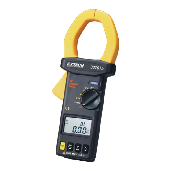
Introduction Congratulations on your purchase of the Extech Model 382075 Auto Range Power Clamp-On Meter. Careful use of this device, will provide years of reliable service. Meter Functional Description 1. Transformer Jaw Used to sense current signal. To measure current or power, Figure 1 the conductor under test must be fully enclosed by the jaw. -
Page 3: Ac/Dc Voltage Measurements
www.burntec.com Operating Instructions NOTE: Ensure that the jaws are clear of any conductors before applying power to the meter. The meter performs an auto zero upon power-up to null any residual magnetism. If this is done with a conductor inside the jaw area, the auto zero function will cause subsequent measurements to be inaccurate. -
Page 4: Ac/Dc Current Measurements
www.burntec.com AC/DC Current Measurements Current (A) + Frequency (Hz) Dual Display WARNING: 1. When applying power to the meter, make sure the clamp jaws are not near a conductor. 2. Make sure that test leads are disconnected from the meter during current measurements. 1. - Page 5 www.burntec.com INDUCTIVE LOAD: A negative phase angle indicates that the current signal lags the voltage signal. A negative phase angle also indicates an inductive load. CAPACITIVE LOAD: A positive phase angle indicates that the current signal leads the voltage signal. A positive phase angle also indicates a capacitive load. NOTE: The "+"...
- Page 6 www.burntec.com Select one phase (S or L2, for example) as COM and connect the COM (black) terminal to that phase (S or L2). g. Connect V (red) terminal to the second phase (R or L1). h. Clamp on to the same phase as in step g. (R or L1). The power clamp will automatically select the proper range.
- Page 7 www.burntec.com φ 4W Unbalanced Power Measurements The measurements of W (or W ), W (or W ), and W (or W ) are required for these measurements. 1. First, measure W (or W ) (Fig. 9). a. Apply power to the meter with the jaw clear of any conductors. b.
- Page 8 www.burntec.com 3.Thirdly, measure W (or W ). See Fig. 11. 3 Phase 4 Wire Disconnect the test lead from the phase T (L3) R(L1) where the Jaw was connected in the S(L2) section entitled "3φ3W Unbalanced 3 Phase Current > T(L3) Power Measurements".
-
Page 9: Φ 3W Power Measurement
www.burntec.com φ 3W Power Measurement 1φ3W power measurements are similar to 3φ3W unbalanced power measurements except that the nomenclature is different. Two measurements of W (or W ) and W (or W ) are required 1. First, measure W (or W ). -
Page 10: Power Factor (Pf)
www.burntec.com φ Calculation of 3 4W Power Factor (PF) When measuring 3φ4W unbalanced power, use the REC button to record the individual power factors , PF , KW , PF , KW , and PF ) of each phase in memory. 3φ4W power factor can R(L1) R(L1) S(L2) -
Page 11: Recording Data
www.burntec.com Phase Sequence Indication (for Power Factor > 0.1) In the 3φ balanced power mode the meter will automatically detect the phase relationship between three individual phases. 1. Set the rotary switch to the 3φ position. 2. Connect the voltage input (red terminal) to the ‘R’ (or L1) phase, connect the COM input (black terminal) to the ‘S’... -
Page 12: Specifications
www.burntec.com Specifications General Specifications Conductor Size Cable Φ55mm. (approx.) Bus Bar 65mm (D) x 24mm (W) Display Dual 4-digit 9999 count LCD Sampling time 0.5 seconds for Voltage and Current; 1.6 seconds for Watts Overload Indication ‘OL’ displayed on LCD Power 9V Battery (Heavy Duty Type) Power consumption... -
Page 13: Battery Replacement
Warranty EXTECH INSTRUMENTS CORPORATION warrants the basic instrument to be free of defects in parts and workmanship for one year from date of shipment (a six month limited warranty applies on sensors and cables). If it should become necessary to return the instrument for service during or beyond the warranty period, contact the Customer Service Department at (781) 890-7440 for authorization.
Need help?
Do you have a question about the 382075 and is the answer not in the manual?
Questions and answers