Table of Contents
Advertisement
Quick Links
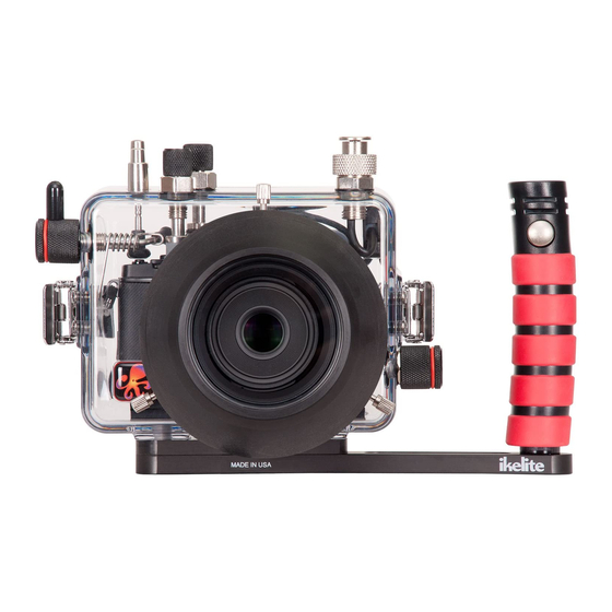
6 95 0 .5 2 Underwater TTL Housing fo r
Olympus OM-D E-M5 Mark II
I n s t r u c t i o n M a n u a l
Thank you for your purchase of Ikelite equipment. Please read this
instruction manual completely before attempting to operate or dive
with this product. Please refer to the back page of this manual to
register your Ikelite product.
Advertisement
Table of Contents
Troubleshooting

Related Manuals for Ikelite 6950.52


Summary of Contents for Ikelite 6950.52
- Page 1 Olympus OM-D E-M5 Mark II I n s t r u c t i o n M a n u a l Thank you for your purchase of Ikelite equipment. Please read this instruction manual completely before attempting to operate or dive with this product.
-
Page 2: Table Of Contents
Strobe Compatibility ............P. 15 Ikelite Housing Conversion Circuitry ......P. 15 Attaching a Sync Cord to the Housing ......P. 15 - 16 Attaching an Ikelite Strobe Arm to the Housing Handle..P. 17 Spare Parts ..............P. 18 Recommended Accessories ........P. 18 Maintenance ..............P. 19 - 22... -
Page 3: Preparation
Table of Contents continued Photo Tips ..............P. 23 Troubleshooting ............P. 24 - 26 Customer Support ............P. 26 Limited Warranty ............P. 27 Returning Products for Service ........P. 27 Product Registration ..........Back Page Preparation This product has been water pressure tested at the factory and is depth rated to 200 ft (60m). -
Page 4: Specifications
..........Diopter Adjustment Dial, and External Flash ..........Connector Buoyancy ......Near neutral in freshwater Depth Rating......200 ft (60m) Strobe Connection ....Ikelite Digital TTL ICS-5 5-pin Electrical ..........Bulkhead plus TTL circuitry compatible with ..........current model Ikelite DS-series strobes Built-in Flash ......None Tray and Handle Weight ..8.7 oz (247 g) Main O-Ring ......0110... -
Page 5: Parts Of The Housing - Front View
Parts of the Housing - Front View Housing controls are provided for all camera functions except the dioptric adjustment dial. Movie Button ON/OFF Lever Fn2 Button External Strobe Shutter Connector & Cap Button Rear Dial Front Dial HDR Button Lens Port Base Lid Snap Lens External Tray Mounts... -
Page 6: Parts Of The Housing - Back View
Parts of the Housing - Back View LV Button MENU INFO 1. Mode Dial LEFT Arrow 8. OK Button 2. Super Eye Viewfinder 3. Lever Function Control RIGHT Arrow 4. MENU Button DOWN Arrow 5. INFO Button Erase Button UP Arrow Playback Button... -
Page 7: Housing And Camera Setup
Housing and Camera Setup STEP 1 - Attach Tray and Handle to the Housing Skip STEP 1 if Tray is factory installed. Using a 9/16” open/box end or socket Wrench (not supplied), firmly tighten the External Tray and Spacer to the Housing Base using the two 3/8-16 Nuts and Washers supplied in the accessory package. -
Page 8: Step 2 - Initial Camera Settings
STEP 2 - Initial Camera Settings Setup your camera for underwater use and then adjust your settings once underwater. Insert a fully charged camera battery and a SD card. Set Mode Dial to “M” Manual Mode. Set Aperture to f/8 and shutter speed to 1/125th second. -
Page 9: Step 3 - Opening The Housing
STEP 2 - Initial Camera Settings - Manual Flash continued you are now in manual flash mode and the lightning bolt flash ready indicator will disappear from the monitor and there will be no more preflashes. To go back to TTL mode, power the strobe off and then on again. Additional information can be found in the Olympus camera manual. - Page 10 STEP 4 - Install Camera/Hotshoe in Housing - continued Diagram A Pull to Remove Mounting Plate Mounting Tray 4. Using a coin or flathead screwdriver (preferred), secure the camera Mounting Tray to the camera tripod mount, Diagram B. Tighten camera firmly to avoid movement on tray.
- Page 11 STEP 4 - Install Camera/Hotshoe in Housing - continued 6. Slide the Hotshoe into the top camera mount until it stops. Hotshoe must be all the way forward in the camera mount to assure a good electrical connection with a strobe, Diagram C, below. Make sure hotshoe cord does not interfere with controls or the housing back when closing the housing.
-
Page 12: Step 5 - Closing The Housing
CAUTION: This housing does not come with a lens port. An optional Mirrorless Lens Port must be properly attached to the housing before submersion in water; see ikelite.com for compatible lens/port combinations. After purchasing an optional port for your lens, reference your port instruction manual for proper installation procedure. -
Page 13: Step 7 - Final Check
STEP 7 - Final Check The clear housing permits instant visual inspection of the camera and sealing surfaces as well as complete monitoring of controls and camera LCD screens. This housing has been factory water pressure tested to 200 ft (60 m). Once the housing is closed, recheck the o-ring seal. -
Page 14: Removing The Camera From The Housing
Removing the Camera from the Housing 1. Thoroughly dry housing. 2. Remove the housing back, see Step 3, Opening the Housing, Page 9. 3. Remove the Hotshoe from the camera mount. 4. Place the index and middle fingers of your left hand over the top of the camera and gently pull backward to separate from housing. -
Page 15: Strobe Use And Compatibility
Attaching a Sync Cord to the Housing - Diagram E, Page 16 The Housing Bulkhead is designed to accept sync cords with Ikelite 5 pin connector fittings. 1. Lightly lubricate the Sync Cord O-ring. Use ONLY Ikelite lubricant (supplied with housing). -
Page 16: Attaching A Sync Cord To The Housing
NOT use pliers or other tools to tighten the Knurled Nut. Always remove the Sync Cord from your Housing when not in use and replace the Bulkhead Cap. Diagram E Ikelite TTL Sync Cord Knurled Nut Bulkhead Sync Cord O-ring... -
Page 17: Attaching An Ikelite Strobe Arm To The Housing Handle
To attach an Ikelite Arm to your Housing Handle, depress the spring-loaded Handle Push Button until it stops. Gently slide the pronged end of the Ikelite Arm into the hole in the top of the Handle as shown below, Diagram F. -
Page 18: Spare Parts
9104.5 Waterproof bulkhead cap Recommended Accessories Mirrorless Interchangeable Lens Ports Visit ikelite.com to select the correct Mirrorless Ports for your lenses. Tray + Dual Handles 9523.64 Attaching an optional Tray + Dual Handles will add stability and gripping point(s) for comfortable use of the housing. -
Page 19: Maintenance
Lubricant Ikelite provides silicone lubricant with the housing. We recommend you use only Ikelite lubricant on Ikelite products. Other brands may cause o-rings to swell and not seal properly. Use only enough lubricant to lightly cover the Port Base O-ring, or lubricate a sticky control. -
Page 20: Housing Maintenance
Housing Maintenance Your Ikelite Digital Housing should be given the same care and attention as your other photographic and video equipment. In addition to normal maintenance, we recommend that the housing be returned to Ikelite periodically to be checked and pressure tested. -
Page 21: Control Maintenance
After a few minutes, operate the push button. If this does not correct the problem, return the housing to Ikelite for maintenance. If you are on a trip and unable to return the housing immediately, a push button may be lubricated by pressing and holding the push button all the way in. - Page 22 In the unlikely event one of the larger gland style control shafts sticks or becomes difficult to operate, you can remove the control from the housing and lubricate it, or return the housing to Ikelite for maintenance. To remove the control, Diagram H, loosen the set screw in the knob (allen wrench required);...
-
Page 23: Photo Tips
Photo Tips The number one rule in underwater photography is to eliminate as much water between the camera and subject as possible. Get as close as you can to the subject, then use the zoom. If you are using flash for still photos, subjects beyond 6 feet (1.8m) will not have much color regardless of strobe power. -
Page 24: Troubleshooting
If still sticky, see the Control Maintenance section, Diagram H, Page 22. - Return housing to Ikelite for routine maintenance. - Check that the strobe is firing when taking a Image is picture. - Page 25 Place one or two new packs in your housing before each day of diving. - If moisture or water droplets are present around the controls or sealing areas, return the housing to Ikelite for evaluation. - Clean the main housing o-ring and sealing surface of the housing.
-
Page 26: Customer Support
- Look for hair, dirt, or foreign debris crossing the o-ring seal. - Reassemble the housing without a camera installed and pressure test or take diving. - Return housing to Ikelite for evaluation. Pictures are too blue - Use custom (manual) white balance when NOT or too green using an external strobe. -
Page 27: Limited Warranty
This Ikelite product is warranted against any manufacturing defects for a period of one (1) year from the original date of purchase. Defective products should be returned to Ikelite postage paid. Ikelite will, at its sole discretion, repair or replace such products, and will return to customer postage paid. -
Page 28: Product Registration
Product Registration Please go to ikelite.com to register your Ikelite housing within 15 days of purchase. Ikelite Underwater Systems 50 West 33rd Street Indianapolis, IN 46208 USA ikelite.com © 2015 Ikelite Underwater Systems 6950.01_Olympus_OMD-EM5II_01-0615...
Need help?
Do you have a question about the 6950.52 and is the answer not in the manual?
Questions and answers