Table of Contents
Advertisement
Quick Links
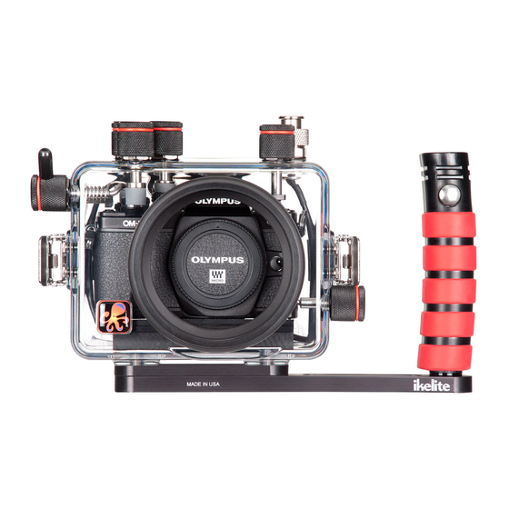
200DLM/A Underwater TTL Housing for Olympus
OM-D E-M10 Mark II Mirrorless Micro Four-Thirds
Cameras
Product # 6950.12
Product Registration
Please register your product within 15 days of purchase. Our product
registration database is the quickest way for us to contact you in the
event of a product update.
To register, send a photo of the above registration label to us via
ikelite@ikelite.com along with your name, address, and phone
number.
Advertisement
Table of Contents

Related Manuals for Ikelite 6950.12


Summary of Contents for Ikelite 6950.12
-
Page 1: Product Registration
To register, send a photo of the above registration label to us via ikelite@ikelite.com along with your name, address, and phone number. -
Page 2: Introduction
1962. We are available if you have any questions or want photo advice. Send us an email 24 hours a day to ikelite@ikelite.com. We strive to reply within 1 business day. An electronic version of this instruction manual is available for download via the product page on our website: https://www.ikelite.com... -
Page 3: Important Notices
Important Notices This housing requires a compatible DLM lens port for » waterproof operation. The housing is not waterproof without a DLM lens port attached. A bulkhead cap or sync cord must be attached to the housing » bulkhead for waterproof operation. Never submerge the housing in water without either a sync cord or bulkhead cap attached. -
Page 4: Table Of Contents
Contents Product Registration Introduction In the Box Important Notices Getting to Know Your Housing Tray Mounts Setting Up Your Camera Pre-Installation Checklist Camera Settings Exposure Settings Setting Up Your Housing Opening the Housing Installing the Camera Attaching the Hotshoe Closing the Housing Attaching a Lens Port Installing the Lens and Port Setting Up An External Strobe... - Page 5 Lens Port Storage Servicing Recommendations Lubricating Controls Lubricating Push Buttons Lubricating Control Shafts Troubleshooting Spare Parts Limited Warranty Service and Repairs Contact Us...
-
Page 6: Getting To Know Your Housing
Getting to Know Your Housing Bulkhead Port mount with cap Shutter Tray mounts Lens Lid snap release... - Page 7 Live view Viewfinder MENU INFO 6950.52 MADE IN USA Rear o-ring snap hook Menu Info MENU INFO Left Right Down 6950.52 Playback Erase MADE IN USA...
- Page 8 Front o-ring Thumbscrew Front dial groove Bulkhead without cap Rear dial On/off Mode dial...
-
Page 9: Tray Mounts
Tray Mounts This housing features two 3/8-16 threaded tray mounts on the bottom of the housing. The spacing between the tray mounts is 3” (76.2 mm). Optional tray with dual handles and mounting hardware are sold separately. It is recommended to detach and thoroughly rinse the tray mounts, tray, and mounting hardware, with fresh water routinely during continuous use and prior to storage. -
Page 10: Exposure Settings
Photo School section of our website for recommendations on exposure settings for a wide variety of shooting situations: https://www.ikelite.com/blogs/cheat-sheets Setting Up Your Housing Opening the Housing 1. Push the lid snap lock forward and lift the curved end away from the housing. -
Page 11: Installing The Camera
Installing the Camera 1. Remove any lanyard or neck strap which may be attached to the camera. 2. Remove the camera mount plate from the housing. 3. Line the mount screw up with the camera’s tripod socket. Use a flat screwdriver to tighten the mount plate to the camera. -
Page 12: Attaching The Hotshoe
Attaching the Hotshoe 1. Orient the hotshoe with the arrow on top pointing towards the front of the camera. Camera hotshoe mount Housing hotshoe 2. Slide the housing hotshoe into camera’s hotshoe mount until it stops. The hotshoe must be all the way forward in the camera mount »... -
Page 13: Attaching A Lens Port
5. Push the lid snaps towards the housing until they are flat against the housing and the lock has engaged. Close both lid snaps at the same time. 6. Check the o-ring seal. The o-ring should form a uniform, solid line visible through the back of the housing. - Page 14 4. Loosen the port thumbscrews until they do not show on the inside of the lens port. 5. If using a port with a dome shade, align the port so that the tall projections on the dome shade are in the 12 and 6 o’clock positions.
- Page 15 6. Press the port firmly towards the housing until the base of the port is almost flush with the housing front. If there is resistance, remove the port and re-check that the thumbscrews are loosened and the o-ring is properly lubricated. Small gap ~ 0.15”...
-
Page 16: Setting Up An External Strobe
TTL Strobe Compatibility When compatible Ikelite DS strobe(s) are attached by electrical sync cord, the TTL circuitry built into the housing allows the camera to communicate directly with the attached strobe(s). The camera triggers the strobe(s) and adjusts the strobe(s) power automatically for perfect exposure. -
Page 17: Attaching An Electrical Sync Cord
Strobes from SEA&SEA, INON, and other manufacturers may be attached by electrical sync cord. These strobes are not capable of powering the TTL circuitry built into this housing. Non-Ikelite strobes must be used in manual power modes. Attaching an Electrical Sync Cord 1. -
Page 18: Shooting Manual Flash With A Ds Strobe
3. Align plug and insert into the housing bulkhead. Each male pin mates with a female receptacle. Failing to line up the contacts properly before tightening may result in damage to the converter plug and/or housing bulkhead. 4. Hand-tighten the retaining ring. 5. -
Page 19: Getting In The Water
Getting in the Water Final Check 1. Re-check the rear o-ring seal. The seal should form an even, solid line visible through the back of the housing. 2. Turn on the camera and check all control functions. 3. Make sure the camera can take a photo. 4. -
Page 20: Shooting Underwater
Learning about Underwater Photography Visit the Photo School section of ikelite.com for a wide range of information on shooting underwater including: • Product Tutorials Videos •... -
Page 21: Maintaining Your Housing
• Feature Articles and more! Maintaining Your Housing Post-Dive 1. Rinse the housing in fresh water. Rotate the housing controls and press each button several times while submerged in fresh water to flush out any salt or debris to ensure smooth operation on future dives. -
Page 22: Storage
Servicing Recommendations It is recommended that the housing be sent to Ikelite or an authorized service center annually for routine service and maintenance. Service may be required more or less frequently depending on care and use. -
Page 23: Lubricating Controls
Remove controls for lubrication only if they continue to stick after applying a small amount of lubricant to the exposed portion of the shafts and working them many times. Use only Ikelite lubricant. Other types of lubricant may cause » swelling of o-rings or cracking of plastic components. -
Page 24: Lubricating Control Shafts
After a few minutes, operate the push button. If this does not correct the problem, return the housing to Ikelite for maintenance. To prevent build-up of salt, sand, or debris, the push buttons »... - Page 25 4. If there is a spring associated with the control, make sure it is in its proper position. Knob Housing Control Control gland shaft screw Control flat 5. Re-install the shaft from the inside of the housing. Rotate the shaft gently for smooth installation into the gland.
-
Page 26: Troubleshooting
DO NOT pull the shutter trigger without a camera installed. You » may accidentally detach or damage the control spring. Troubleshooting Water enters the housing • Check and reinstall the rear o-ring. • Replace the o-ring if there are any signs of cracks or tears. •... - Page 27 • Restore the camera to factory default settings. There are some camera settings that will prevent an external flash from firing. • Check camera settings recommended for use with an external strobe in the beginning of this manual. • Check that the sync cord is properly attached. •...
-
Page 28: Spare Parts
All other claims of any nature are not covered. Except as mentioned above, no other warranty expressed or implied applies to this Ikelite product. Service and Repairs Ikelite is most interested in performing any service to ensure that all products perform as intended. -
Page 29: Contact Us
Always include name, shipping address, email address, and phone number inside of the package. Send postage paid to: Ikelite Underwater Systems Attention: Service Department 50 W 33rd St Indianapolis, IN 46208 USA +1 (317) 923-4523 service@ikelite.com...
Need help?
Do you have a question about the 6950.12 and is the answer not in the manual?
Questions and answers